manuals.online logo
Brands
  1. Home
  2. •
  3. Brands
  4. •
  5. Sansui
  6. •
  7. Tuner
  8. •
  9. Sansui tu-x701 User manual

Sansui tu-x701 User manual

TU-X701 TU-X701
10. DESCRIPTION OF ICs, TC9306 AND CXP5014 11 . INTERIOR BLOCK DIAGRAM OF ICs
- LC7217 (PLL Synthesizer)
-TC9306-007
..::::
Digital Tuning System Control;:::.
o",~ ;;;~2
(f)(f)U(f)
::;;
Q.Q.
w Z
C( -
0 6
;,:
.. ;:: N
N M M '"
Q.Q.~
'" ..~ ~ ~
45 44 43 42 41 40 39
26
25
,::! 24 VDD
COM1
S27
S26
S25
S24
S23
S22
REF
iNT
iNH
TEST
Xl'
GND
VDD
COM2 .54
Serial
Interface I/O Port
Driver
~"' ",.. """
~"'m
(f)(f) (f) (f) (f) (f) (f) (f) (f) (f) (f) (f) (f) (f) (f)
. TC9306-007
..::::
Terminal Function;:::.
Pin No. Pin Name Function
COM1 Terminal for outputting common signals to FL
COM2 display driver IC.
Note: The output is fixed at " L" level automat-
ically when the system is reset or ex-
ecuting CK STP instruction.
1- 21 S7- S27 Terminals for outputting segment signals to FL
55- S1- display driver IC. A control of a maximum of
54 segments is possible on the basis of matrix
with COM1 and COM2, Data are outputted
through these terminals when SEG instruction
(COM1 system) or MARK instruction (COM2
system) is executed.
Note: The output is fixed at "L" level when
the system is reset or excuting CK STP
instruction.
-CXP5014 ..:::: FL Display Driver;:::.
N_O ~O ~-'r':~
xxxoz'-'w'-"-'x
;::~~
Q.Q.Q.'-'~ZC(Zzwxo~
~&J~;;:~;nU~g(j)~~U\
Q.Q.Q.Q.Q.
'-'
-LC3450 (MPX)
~ '"
"'6
~~ ~ ~~ ~
~~ s~ ~~ ~~
~~ ~~ ~
6 ~~ ~6 ~5 5~ 58
Pin No. Pin Name Function
24- KO- Ports for inputting a 4-bit key matrix signal.
On the other hand, key return timing signals
are outputted from output ports TO to T6.
28 - 34 TO - T6 Ports for outputting key matrix return timing
signals. A 4-bit signal is outputted from TO to
T3, while a 3-bit signal is outputted from T4
to T6.
AID IN Terminals for inputting analog signals to 4-bit
DC.REF built-in AID converter. The built-in AID con-
verter is of successive comparison type in de-
pendence upon program, A reference voltage
is inputted through DC.REF and an analog con-
parison voltage is inputted through AID IN.
MUTE A port for outputting a mute control signal.
Note: This output~et to "L" level automat-
ically when INH input changes from "
to "L" or vice versa.
STB Serial interfaces fo.r STB (strobe pulse output)
LC7217, CK (serial clock output), SO (serial
data output), and SI (serial data input),
LC7217 PLL IC is controlled by executing SIO
instruction,
Terminal for outputting a reference frequency
signal supplied to LC7217 PLL IC.
Note: This output is fixed at " L" level auto-
matically when INH input is at "L" level.
INT Terminal for inputting~ystem resetting sig-
nal to device. When INT is at "L" level, the
device is reset; when at "H" level , program
starts beginning from address No,O. This ter-
minal is usually fixed at "H" level, because the
device is reset when a voltage of 4.5V is ap-
plied to VDD. (power-on reset)
TEST Terminal for inputting a test mode control sig-
nal. The device is returned to the ordinary
operation at " L" level or in NC status. This
terminal includes a pull-down resistor and is
fixed at " L" level usually.
Terminals for connecting a quartz oscillator of
7.4 MHz.
GND GND Terminal
VDD Terminal for applying a device supply voltage.
In the normal operation, a voltage of 5V", 1 0%
is applied; but in back-up condition, the vol-
tage can be reduced to 2V. Further, when a
voltage of 4.5V is applied to this terminal, the
device is reset and then program starts begin-
ning from address No. O (power-on reset).
"0
~~
1ij~ ~ :i'
::;
~~ d ~~
~~ ~~ ~
-TA7302P (FM IF Amp.
l01
jlPC1163H (FM IF Amp. -LA1245 (AM Tuner)
. CXP5014 ..::::Terminal Function;:::'
POl
XDUT PD2
LCTR
OUTD OUT!OUT2 OUT3OUT. OUTS OUT6INO INI
-LA1235 (IF Amp..Detector.Muting.
Signal Meter Drive)
vcc
7 )~U
~~;~
S. Metee
-NjM2043D (OP Amp.
I ) Vcc
Pin No. Pin Name ilO Description
PX3, PDO- Terminal for inputting a FL display indicator
PCO- 3, PFO- driving signals.
PEO- 3, PBO-
PAO-
62- PXO-
COM2 Terminal for inputting common signal for FL
display.
26, VDD Terminals for applying a device supply
voltage.
GND GND Terminal
28 - 43 S1- S15 Terminals for outputting segment signals to
FL display.
46- T5 - TO Terminals for outputting grid signals to FL
display,
VFDP Terminal for connecting a supply voltage (-
to filament of FL display.
DUTY Terminal for setting a display mode for FL
display.
Norminally this terminal is kept in "L" level.
, XT Terminal for connecting a quartz oscillator
of 3. 6 MHz.
RESET Terminal for inputting a reset signal.
COM1 Terminal for inputting common signal for FL
display.
A-OUT I v +
z.. B - OUT
6 B- IN
V- 4 5 B+IN
Top View
SANSUI ELECTRIC CO" LTD,
SANSUI ELECTRONICS CORPORATION:
14- , Izumi 2-chome, Suginami-ku, Tokyo 168 japan
PHONE: (03! 324-8891 /TELEX: 232-20.76 IInternational Division!
1250 Valley Brook Ave, Lyndhurst, N,j, 07071 U,
17150 South Margay Ave, Carson, Calitornia 90746 U,
3036 Koapaka Street, Honolulu, Hawaii 96819 U.
Unit 10A, Lyon Industrial Estate, Rockware Avenue, Greenford, Middx U86, OAA, England
Paul Ehrich Strasse 8, 6074 Rodermark 2, West Germany
HE~i*J,&~J11) -It-I::: :AHtjjtJ11) **'l:B=liImT~if8- 9-16(T18l) ~,i'i0422-46-8131
SAN SUI ELECTRONICS (U, I LTD,
SANSUI ELECTRONICS G,
LlJ7./(~5tltt~~t.t
SAN SUI (SM2- Printed in Japan (1987,07, M) ~Stock No, 36531500)0

This manual suits for next models

1

Other Sansui Tuner manuals

Sansui TU-666 Troubleshooting guide

Sansui

Sansui TU-666 Troubleshooting guide

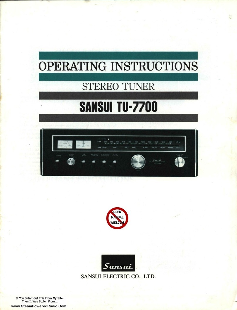
Sansui TU-7700 User manual

Sansui

Sansui TU-7700 User manual

Sansui T-80 User manual

Sansui

Sansui T-80 User manual

Sansui T-700 User manual

Sansui

Sansui T-700 User manual

Sansui TU-S77AMX User manual

Sansui

Sansui TU-S77AMX User manual

Sansui TU-505 Troubleshooting guide

Sansui

Sansui TU-505 Troubleshooting guide

Sansui TU-9900 User manual

Sansui

Sansui TU-9900 User manual

Sansui TU-717 User manual

Sansui

Sansui TU-717 User manual

Sansui TU-9900 User manual

Sansui

Sansui TU-9900 User manual

Sansui 1000X User manual

Sansui

Sansui 1000X User manual

Sansui TU 777 Troubleshooting guide

Sansui

Sansui TU 777 Troubleshooting guide
Sansui DR201V User manual

Sansui

Sansui DR201V User manual

Sansui TU 777 Troubleshooting guide

Sansui

Sansui TU 777 Troubleshooting guide

Popular Tuner manuals by other brands

Sirius Satellite Radio 102405b installation guide

Sirius Satellite Radio

Sirius Satellite Radio 102405b installation guide

Philips AH673/44 owner's manual

Philips

Philips AH673/44 owner's manual

Yamaha TX-396L owner's manual

Yamaha

Yamaha TX-396L owner's manual

MFJ MFJ-974H instruction manual

MFJ

MFJ MFJ-974H instruction manual

Akai AM-U11 Service manual

Akai

Akai AM-U11 Service manual

Panasonic CY-DAB2000N operating instructions

Panasonic

Panasonic CY-DAB2000N operating instructions

Clarion VRX8271 Owner's guide and installation manual

Clarion

Clarion VRX8271 Owner's guide and installation manual

Yamaha TD-36ML owner's manual

Yamaha

Yamaha TD-36ML owner's manual

Traynor TT2M user manual

Traynor

Traynor TT2M user manual

Yamaha TX-950 owner's manual

Yamaha

Yamaha TX-950 owner's manual

Sirius Satellite Radio SiriusConnect SIR-KEN1 installation guide

Sirius Satellite Radio

Sirius Satellite Radio SiriusConnect SIR-KEN1 installation guide

Cambridge Audio T Series owner's manual

Cambridge Audio

Cambridge Audio T Series owner's manual

Roadie RD200 product manual

Roadie

Roadie RD200 product manual

AMC XT Service manual

AMC

AMC XT Service manual

Magnum MD 108T instruction manual

Magnum

Magnum MD 108T instruction manual

McIntosh MR 7083 owner's manual

McIntosh

McIntosh MR 7083 owner's manual

AMC MP01 user manual

AMC

AMC MP01 user manual

Arcam T51 Service manual

Arcam

Arcam T51 Service manual

manuals.online logo
manuals.online logoBrands
  • About & Mission
  • Contact us
  • Privacy Policy
  • Terms and Conditions

Copyright 2025 Manuals.Online. All Rights Reserved.