manuals.online logo
Brands
  1. Home
  2. •
  3. Brands
  4. •
  5. Kenwood
  6. •
  7. Tuner
  8. •
  9. Kenwood KT-2010 User manual

Kenwood KT-2010 User manual

QUARTZ
SYNTHESIZER
AM/FM
STEREO
TUNER
KT-2010/KT-2010L
INSTRUCTION
MANUAL
KENWOOD
CORPORATION
GOO/ANS>DI
B50-9593-00
CSD
(E,
T,
U,
UE)
(G)
89/12
111098765432
Introduction
ri
mmm
Your
choice
of
this
product
indicates
that
you
are
a
devotee
to
excellence
in
sound
reproduction.
We
appreciate
your
patronage
and
take
pride
in
the
long
tradition
of
quality
components,
that
our
company
repre-
sents.
So
that
you
can
get
the
most
out
of
your
unit,
we
suggest
that
you
take
the
time
to
read
through
this
manual
before
you
hook
up
and
operate
your
system.
This
will
acquaint
you
with
operating
features,
and
system-connection
con-
siderations,
so
that
your
listening
pleasure
will
be
en-
hanced
right
from
the
start.
You
will
notice
that
in
all
aspects
of
planning.
engineering,
styling.
operating
con-
venience
and
adaptability,
we
have
sought
to
anticipate
your
needs
and
desires.
Keep
this
manual
handy
for
future
reference.
For
your
records
Record
the
serial
number,
found
on
the
back
of
the
unit,
in
the
spaces
designated
on the
warranty
card,
and
in
the
space
provided
below.
Refer
to
the
model
and
serial
numbers
whenever
you
call
upon
your
dealer
for
informa-
tion
or
service
on
this
product.
Model
Ss
Serial
Number.
Unpacking
Unpack
the
unit
carefully
and
make
sure
that
all
accesso-
ries
are
put
aside
so
they
will
not
be
lost.
Examine
the
unit
for
any
possibility
of
shipping
damage.
If
your
unit
is
damaged
or
fails
to
operate,
notify
your
dealer
immediately.
If
your
unit
was
shipped
to
you
directly,
notify
the
shipping
company
without
delay.
Only
the
consignee
(the
person
or
company
receiving
the
unit)
can
file
a
claim
against
the
carrier
for
shipping
damage.
We
recommend
that
you
retain
the
original
carton
and
packing
materials
for
use
should
you
transport
or
ship
the
unit
in
the
future.
Contents
Introduction
A\
Before
applying
power
A
Safety
precautions
A
Important
safeguards
System
connections
Controls
and
indicators
Operating
instructions
How
to
adjust
the
time
Listening
to
radio
broadcasts
2
KT-2010/KT-2010L
(En)
Note
to
CATV
system
installer:
This
reminder
is
provided
to
cail
to
the
CATV
system
installer’s
attention
to
Article
820-22
of
the
NEC
that
provides
guidelines
for
proper
grounding
and,
in
particu-
lar,
specifies
that
the
cable
ground
shall
be
connected
to
the
grounding
system
of
the
building,
as
close
to
the
point
of
cable
entry
as
practical.
Accessories
®
AM
loop
antenna
(The
shape
of
the
re
antenna
provided
may
differ
depending
on the
area.)
®
FM
indoor.
antenna
..:
®
antenna
adaptor
(KT-2010L
only)
@
®
audio
cord
OS,
Caution:
Read
the
following
pages
marked
in
A\
carefully
to
keep
your
safety.
Tuning
to
a
broadcasting
station
Preset
scanning
How
to
preset
How
to
change
the
station
name
Using
the
audio
timer
Program
timer
function
Sleep
timer
function
In
case
of
difficulty
Specifications
A\
Caution:
Read
this
page
carefully
to
keep
your
safety.
Before
applying
power
For
the
U.S.A.
and
Canada
Important!
Units
shipped
to
the
U.S.A.
and
Canada
are
designed
for
operation
on
120
volts
AC
only.
Safety
precaution
for
a
Polarized
AC
plug
CAUTION:
To
PREVENT
ELECTRIC
SHOCK
DO
NOT
USE
THIS
(POLARIZED)
PLUG
WITH
AN
EXTENSION
CORD,
RECEPTACLE
OR
OTHER
OUTLET
UNLESS
THE
BLADES
CAN
BE
FULLY
INSERTED
TO
PREVENT
BLADE
EXPOSURE.
For
the
United
Kingdom
Important!
Units
shipped
to
the
U.K.
are
designed
for
operation
on
240
volts
AC
only.
The
mains
plug
must
be
removed
from
the
wall
socket
prior
to
any
internal
examination.
The
wires
in
this
mains
lead
are
coloured
in
accordance
with
the
following
code:
Neutral
The
wires
in
this
mains
lead
must
be
connected
to
the
terminals
in
the
plug
as
follows:
Wire
colour
Plug
terminal
marking
N
or
Black
L
or
Red
Brown
to
Live
Biue
to
Neutral
wv
)
Plug
Notes:
1.
If
a
13-amp
plug
is
used,
this
must
be
fitted
with
a
5-
amp
fuse.
2.
If
a
3-pin
plug
with
earthing
contact
is
used,
no
wire
must
be
connected
to
the
E
terminal.
Safety
precautions
For
Australia
and
Europe
Important!
Units
shipped
to
Australia
are
designed
for
operation
on
240
V
AC
only.
Units
shipped
to
Europe
are
designed
for
operation
on
220
V
AC
only.
For
other
countries
Important!
Units
shipped
to
countries
other
than
the
above
countries
are
equipped
with
an
AC
voltage
selector
switch
on
the
rear
panel.
Refer
to
the
following
paragraph
for
the
proper
setting
of
this
switch.
AC
voltage
selection
This
unit
operates
on
110-120
or
220-240
volts
AC. The
AC
voltage
selector
switch
on
the
rear
panel
is
set
to
the
voltage
that
prevails
in
the
area
to
which
the
unit
is
shipped.
Before
connecting
the
power
cord
to
your
AC
outlet,
make
sure
that
the
setting
position
of
this
switch
matches
your
line
voltage.
If
not,
it
must
be
set
to
your
voltage
in
accordance
with
the
following
directions.
Note:
——2@___
Our
warranty
does
not
cover
damage
caused
by
excessive
line
voltage
due
to
improper
setting
of
the
AC
voltage
selector
switch.
AC110-120V\<4RAC220-240V\
AC110-120V°V-4RAC220-240VV
This
shows
switch
lever
is
locked
in
the
220-240V
~
position.
This
shows
switch
lever
is
locked
in
the
110-120V
‘V
position.
Move
switch
lever
to
match
your
line
voltage
with
a
small
screwdriver
or
other
pointed
tool.
AC
voltage
selector
switch
WARNING:
TO
PREVENT
FIRE
OR
SHOCK
HAZARD,
DO
NOT
EXPOSE
THIS
APPLIANCE
TO
RAIN
OR
MOISTURE.
CAUTION
CAUTION:
TO
REDUCE
THE
RISK
OF
ELECTRIC
SHOCK,
DO
NOT
REMOVE
HISK
OF
EERECTRIC
SHOCK
COVER
(OR
BACK).
NO
USER-SERVICEABLE
PARTS
INSIDE,
REFER
SER-
DO
NOT
OPEN
VICING
TO
QUALIFIED
SERVICE
PERSONNEL.
THE
LIGHTNING
FLASH
WITH
ARROWHEAD
SYMBOL,
WITHIN
AN
EQUILATERAL
TRIAN-
GLE,
IS
INTENDED
TO
ALERT
THE
USER
TO
THE
PRESENCE
OF
UNINSULATED
*“DAN-
GEROUS
VOLTAGE”
WITHIN
THE
PRODUCT'S
ENCLOSURE
THAT
MAY
BE
OF
SUFFICIENT
MAGNITUDE
TO
CONSTITUTE
A
RISK
OF
ELECTRIC
SHOCK
TO
PERSONS.
THE
EXCLAMATION
POINT
WITHIN
AN
EQUILATERAL
TRIANGLE
1S
INTENDED
TO
ALERT
THE
USER
TO
THE
PRESENCE
OF
IMPORTANT
OPERATING
AND
MAINTENANCE
(SER-
VICING)
INSTRUCTIONS
IN
THE
LITERATURE
ACCOMPANYING
THE
APPLIANCE.
KT-2010/KT-2010L
(En)
3
A\
Caution:
Read
this
page
carefully
to
keep
your
safety.
Important
safeguards
Please
read
all
of
the
safety
and
operating
instructions
before
operating
this
unit.
For
best
results,
follow
all
warnings
placed
on the
unit
and
adhere
to
the
operating
and
use
instructions.
These
safety
and
operating
instruc-
tions
should
be
retained
for
future
reference.
1.
Power
sources
—
The
unit
should
be
connected
to
a
power
supply
only
of
the
type
described
in
the
operating
instructions
or
as
marked
on
the
appliance.
2.
Power-cord
protection
—
Power-supply
cords
should
be
routed
so
that
they
are
not
likely
to
be
walked
on
or
pinched
by
items
placed
upon
or
against
them,
pay
particular
attention
to
cords
at
plugs,
convenience
receptacles,
and
the
point
where
they
exit
from
the
unit.
Never
pull
or
stretch
the
cord.
3.
Ventilation
—
The
unit
should
be
situated
so
that
its
location
or
position
does
not
interfere
with
its
proper
ventilation.
To
maintain
good
ventilation,
do
not
put
records
or
a
table-cloth
on
the
unit.
Place
the
unit
at
least
10
cm
away
from
the
walls.
4.
Water
and
moisture
—
The
unit
should
not
be
used
near
water
-
for
example,
near
a
bathtub,
washbowl,
kitchen
sink,
laundry
tub,
in
a
wet
basement,
or
near
a
swimming
pool,
etc.
5.
Temperature
—
The
unit
may
not
function
properly
if
used
at
extremely
low,
or
freezing
temperatures.
The
ideal
ambient
temperature
is
above
+5°C
(41°F).
6.
Heat-
The
unit
should
be
situated
away
from
heat
sources
such
as
radiators,
heat
registers,
stoves,
or
other
units
(including
amplifiers)
that
produce
heat.
4
kT-2010/KT-2010L
(En)
7.
Electric
shock
-
If
a
metal
object.
such
as
a
hair
pin
or
a
needle,
comes
into
contact
with
the
inside
of
this
unit,
a
dangerous
electric
hock
may
result.
For
fami-
lies
with
children,
never
permit
children
to
put
any-
thing.
especially
metal,
inside
this
unit.
8.
Enclosure
removal
—
Never
remove
the
enclosure.
If
the
internal
parts
are
touched
accidentally,
a
serious
electric
shock
electric
shock
might
occur.
9.
AC
outlets
—-
Do
not
connect
other
audio
equipment
with
a
power
consumption
larger
than
that
specified
to
the
AC
outlet
on
the
rear
panel.
Never
connect
other
electrical
units,
such
as
an
iron
or
toaster,
to
it
to
prevent
fire
or
electric
shock.
The
maximum
capacities
indicated
for
the
AC
outlets
on
the
rear
panel
of
this
unit
are
as
follows.
1.
SWITCHED
outlet
:
100
W
(KT-2010)
400
W
(KT-2010L)
2.
UNSWITCHED
outlet
:
700
W
(KT-2010
only)
10.
Cleaning
—
Do
not
use
volatile
solvents
such
as
alco-
hol.
paint
thinner,
gasoline.
or
benzine,
etc.
to
clean
the
cabinet.
Use
a
clean
dry
cloth.
11.
Abnormal
smell—If
an
abnormal:
smell
or
smoke
is
detected,
immediately
turn
the
power
OFF
and
pull
out
the
power
cord.
Contact
your
dealer
or
nearest
service
station.
POWER
OFF!
System
connections
Make
connection
as
shown
in
the
diagram
below.
When
connecting
the
related
system
components,
refer
also
to
the
instruction
manuals
of
the
related
components.
KT-2010
FM
indoor
antenna
FM
outdoor
antenna
AM
loop
antenna
AM
outdoor
antenna
(]
9
KT-2010
ACIIO-\20V—~~
—<§Re
AC220-240¥™~
if
STATION
NAME
im
7.
AND
ee)
|
some
©
|(Resr
—
a)
J
al
¢
Saal
oo
SWITCHED
UNSWITCHED
PRESET
20
100W WAX.
‘7O0W
MAK.
Lf
——__________\
Audic
connection
cord
supplied
300
ohm
feeder
75
ohm
coaxial
cable
=)
To
AC
outlet
System
Control
terminal
When
connected
to
an
amplifier
or
receiver
having
KENWOOD
SYSTEM
CONTROL
terminals,
system
operation
such
as
remote
control
is
made
possible.
For
details,
refer
to
the
instruction
man-
Co}
=
|
fl
jue
ual
of
the
amplifier
or
receiver.
if
your
amplifier
or
receiver
is
not
equipped
with
the
SYSTEM
CONTROL
terminals,
do
not
connect
anything
to
any
SYSTEM
CONTROL
terminal.
Do
not
connect
the
unit
in
any
system
configuration
other
than
specified.
KT-2010/KT-201
OL
(En)
5
System
connections
Make
connection
as
shown
in
the
diagram
below.
When
connecting
the
related
system
components,
refer
also
to
the
instruction
manuals
of
the
related
components.
KT-2010L
(For
U.K.
and
Europe)
FM
indoor
antenna
75
ohm
Feeder
coaxial
cable
/
AM
(MW,
LW)
‘
loop
antenna
t
Py
em
Ko)
V4
\--~fJof--y
"778,
Notes:
1.
Connect
all
cords
firmly.
A
loose
connection
may
not
produce
sound,
but
noise
may
occur.
2.
When
plugging
and
unplugging
a
connection
cord
after
all
connections
are
completed,
be
sure
to
disconnect
the
power
cord
from
the
AC
outlet.
If
a
connection
cords
is
plugged/un-
plugged
with
the
power
cord
connected,
it
may
cause
a
malfunction
or
damage
the
equipment.
3.
Since
this
system
incorporates
microcomputers,
correct
op-
erations
may
not
be
obtained
because
of
external
noise
or
interference,
etc.
In
this
case,
disconnect
the
power
cord,
then
plug
it
in
again.
4.
Do
not
connect
up
a
power
source
which
is
larger
than
that
indicated
on
the
socket
at
the
rear
of
the
unit.
6
kT-2010/KT-20104
(En)
FM
outdoor
antenna
AM
(MW,
LW)
outdoor
antenna
STATION
NAME
00
Nee
J
AND
PRESET
12
<_
PRESET
20
To
wall
AC
outlet
Audio
connection
cord
supplied
@
AM
(MW,
LW)
loop
antenna
Install
the
AM
(MW,
LW)
loop
antenna
on
the
supplied
antenna
holder
and
place
it
on
a
shelf,
etc.,
or
install
it
on
the
rack
or
wall
with
screws.
Rotate
the
AM
(MW.
LW)
loop
antenna
to
the
right
or
left
-,
for
best
reception.
Keep
the
speaker
leads
and
AC
cords
away
from
the
AM
foop
antenna.
Note:
Do
not
place
the
AM
(MW,
LW)
loop
antenna
on
the
unit.
As
this
unit
employs
computing
device,
placing
the
AM
(MW,
LW)
loop
antenna
on
the
unit
may
result
in
noise
generation.
Place
the
AM
(MW,
LW)
loop
antenna
away
from
the
unit.
@
AM
(MW,
LW)
outdoor
antenna
In
steel
buildings
or
at
a
great
distance
from
the
transmit-
ter,
it
may
be
necessary
to
install
an
outside
longwire
antenna.
The
end
of
this
wire
should
be
stripped
of
insulation
and
connected
to
the
AM
terminal.
At
this
time,
keep
the
loop
antenna
connected.
@
FM
indoor
antenna
Connect
the
T-shaped
indoor
antenna
(supplied)
to
the
300
ohm
FM
ANTENNA
terminal
as
shown
in
the
system
connections
diagram.
With
U.K.
and
European-destination
models,
attach
the
75
ohm/300
ohm
antenna
adapter
to
the
indoor
antenna
and
then
connect
the
adapter
to
the
75
ohm
FM
ANTENNA
terminal.
Spread
the
two
arms
that
form
the
top
of
the
“T”
horizontally
and
hold
them
against
convenient
wall
surfaces.
Try
several
locations
for
the
best
results
from
your
favorite
stations.
Tape
the
antenna
in
the
place
where
the
best
compromise
is
found
between
listening
results
and
ap-
pearance.
Connection
of
the
75
ohm/300
ohm
antenna
adaptor
Indoor
antenna
feeder
Loosen
the
screws
with
a
screwdriver.
Insert
the
antenna
terminals
under
the
screw
heads
and
then
tighten
the
screws
firmly.
@
FM
outdoor
antenna
(KT-2010L)
Be
sure
to
use
an
outdoor
FM
antenna
to
receive
good
sound
quality
FM
broadcasts
with
a
minimum
of
noise.
When
connecting
an
outdoor
antenna
to
the
antenna
terminals
of
this
unit,
connect
as
illustrated.
The
75
ohm/300
ohm
antenna
adaptor
is
supplied
with
this
unit
for
U.K.
and
Europe.
Be
sure
to
connect
the
coaxial
cable
to
the
adaptor
as
instructed
in
the
relevant
section.
Note:
——_]__-.$.
__—_$$$AAMA@9qo_dae_iom—M
i
_____—
An
FM
outdoor
antenna
can
be
a
connected
to
the
tuner
with
a
75
ohm
coaxial
cable.
For
proper
connection,
carefully
read
the
instruction
manual
for
the
FM
outdoor
antenna.
©
To
minimize
auto-ignition
noise,
locate
the
antenna
as
far
from
heavy
traffic
as
possible.
®
Keep
the
feeder
or
coaxial
cable
as
short
as
possible.
Do
not
bundle
or
roll
up
excess
cable.
®
The
antenna
should
be
at
least
two
meters
(6.6
feet)
from
reinforced
concrete
walls,
or
metal
structures.
FM
outdoor
antenna
setting
75
ohm/300
ohm
antenna
adaptor
connection
1.
Arrange
the
coaxial
cable
as
illustrated.
Outer
shield
(braid)
Outer
shield
{braid}
Inner
conductor
Inner
conductor
RG6
Lg
Jak,
RG-59
patna
6 3
9.
mm mn
mn
(c-2y)
Lome
(3C-2V)
‘Sree
2.
Open
the
75
ohm/300
ohm
antenna
adaptor
Press
the
claws
in
the
direction
of
the
arrows
with
your
fingers
to
release
the
lock
and
then
pull
off
the
cover.
3.
Connect
the
processed
coaxial
cable
to
the
75
ohm/300
ohm
antenna
adaptor
as
shown
below.
In
the
case
of
RG-6
(5C-2V),
insert
and
wind
the
inner
conductor
around
the
slit.
In
the
case
of
RG-59
(3C
~—
2V),
further
insert
and
wind
the
inner
conductor
around
the
slit.
Detach
the
ring
from
the
antenna
adaptor.
Wind
the
inner
conductor
here.
Ring
Outer
shield
(braid)
75
ohm/300
ohm
Antenna
adaptor
(supplied)
4.
Put
the
ring
on
the
pole
in
the
cover.
Ring
Note:
———_____________
.
To
connect
the
300
ohm
feeder,
attach
the
ring
shown
in
the
figure.
If
the
ring
is
not
attached,
the
sensitivity
decreases.
5.
Close
the
75
ohm/300
ohm
antenna
adaptor.
KT-2010/KT-2010L
(En)
7
System
connections
@
FM
DE-EMPHASIS
switch
(Except
some
areas)
switch
(Except
for
some
areas)
This
switch
has
been
set
to
the
correct
position
for
a
given
market
area.
However,
check
to
see
that
this
switch
is
set
correctly
before
operating
your
unit.
An
incorrect
setting
will
adversely
affect
high-frequency
performance.
Europe
and
OC@aMia
oi...
eceeeeeeeseceeesessseeteeceetenees
50
us
Other
COUNTIES
ives.
chi
sdesssescatidetevesleectesteinesssecdecveeccbeice
75
ps
Note:
When
changing
the
setting
of
the
AM/FM
CHANNEL
SPACE
switch,
first
unplug
the
AC
power
cord,
then
operate
the
switch,
and
finally
insert
the
AC
power
cord
again.
@
AC
outlets
(KT-2010)
The
AC
outlets
on
the
rear
panel
can
be
used
to
supply
power
to
other
components
in
the
system.
Never
connect
equipment
whose
power
consumption
exceeds
the
max-
imum
value
shown
at
each
outlet.
SWITCHED:
This
outlet
supplies
power
when
the
unit
is
set
to
tuner
mode
or
the
built-in
timer
is
activated.
UNSWITCHED:
This
outlet
provides
power
when
the
unit
is
plugged
into
an
active
AC
wall
outlet.
regardless
of
the
setting
of
the
POWER
switch
of
timer.
AC
outlet
(KT-2010L)
SWITCHED:
This
outlet
supplies
power
when
the
unit
is
set
to
tuner
mode
or
the
built-in
timer
is
activated.
SWITCHED
outlet
100
W
400
W
UNSWITCHED
outlet
700
W
@
Output
Signals
from
the
output
jacks
are
fed
to
the
amplifier.
Connection
cables
should
be
plugged
into
the
amplifier
TUNER
or
AUX
jacks.
Shielded
cables
terminated
at
both
ends
with
audio
cords
are
supplied
with
this
tuner.
@
Ground
For
maximum
safety
and
minimum
interference
connect
the
GND
terminal
to
a
good
earth
ground
if
practicable.
A
good
earth
ground
is
a
metal
stake
driven
into
moist
earth.
POWER
key
standby
A
small
amount
of
current
is
used
to
support
the
memory
when
POWER
is
switched
OFF.
This
is
known
as
standby
mode.
8
KT-2010/KT-2010L
(En)
@
AM/FM
CHANNEL
SPACE
switch
(Ex-
cept
some
areas)
The
CHANNEL
SPACE
switch
on the
rear
panel
is
set
to
the
correct
setting
that
prevails
in
the
area
to
which
the
unit
is
shipped.
However,
if
the
channel
space
setting
is
not
matched
to
the
area
where
the
unit
is
to
be
used;for
instance,
when
you
moved
from
area
1
to
area
2
or
vice
versa,
desired
reception
of
AM/FM
broadcasts
is
not
expected.
In
this
case,
change
the
CHANNEL
SPACE
setting
in
accordance
with
the
area
corresponding
to
the
table
shown
below.
Channel
Space
Frq.
1.
U.S.A.,
Canada
FM:
100
kHz
Hawaii,
and
Guam
AM:
10
kHz
FM:
2.
European
countries
50
kHz
Far
East
countries
AM:
9
kHz
Channel
space
table
@
Before
plugging
the
power
plug
into
an
AC
outlet
Set
the
STATION
NAME
AND
PRESET
select
switch
on
the
rear
panel
of
this
unit
to
either
the
12”
or
the
“20”
position
according
to
the
the
number
of
stations
you
want
to
preset.
After
setting
this
switch,
plug
the
power
cord
into
the
AC
outlet.
(For
presetting
operation.
refer
to
page
13,
and
for
tuning
to
preset
stations,
refer
to
page
12.)
When
station
name
display
is
required
display
is
not
required
Switch
on
the
rear
panel
(Set
to
“12”)
(Set
to
“20")
STATION
NAME
STATION
NAME
AND
AND
PRESET
12
PRESET
12
<>
<>
PRESET
20
]
PRESET
20
]
(This
switch
is
set
to
“12”
when
the
unit
is
shipped.)
®
A
total
of
12
FM
or
AM
|
@A
total
of
20
FM
or
AM
stations
can
be
preset
stations
can
be
preset
for
channels
A
and
B.
for
channels
A
and
B.
@
Usable
keys
are
as
fol-
|
©
Usable
keys
are
as
fol-
lows:
lows:
Channel
A:
1-6
Channel
A:
1-0
(A-1
to
A-6)
(A-1
to
A-0)
Channel
B:
1-6
Channel
B:
1-0
(B-1
to
B-6)
(B-1
to
B-0)
Note:
——@——_____$
When
this
switch
position
is
changed,
the
contents
of
the
previously
stored
memory
will
be
cleared.
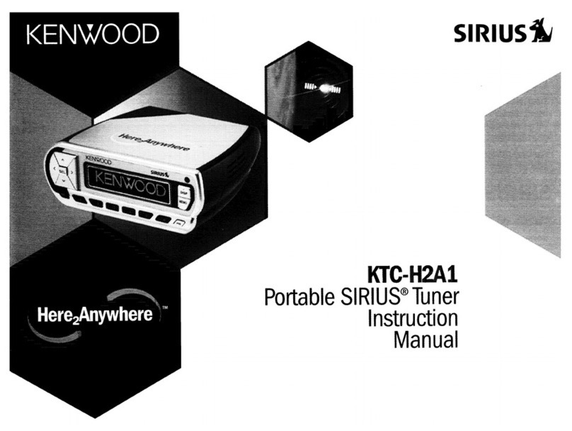
Controls
and
indicators
gn
a
ag
9
a
TN
TUNING/CHARACTER
keys
The
character
display
changes
as
shown
in
the
figure,
P.SCAN
key
each
time
the
TUNING/CHARACTER
key
is
pressed.
—A—-B—C.
Z—+
0+
1+
2
Bere
Q
EXECUTE.1
—
2
key
Space
position
DIRECT
key
PROGRAM
1
key,
PROGRAM
2
key
Band
select
keys
FM,
AM
ADJUST
key
KT-2010L
(FM,
MW,
LW)
DISPLAY
key
CHARACTER
key
CLEAR
key
SLEEP
key
DIGIT
key
ENTER
key
POWER
key
Preset
A/B
select
key
Numeric
keys
(1~0)
AUTO/
;
;
MANUAL
AUTO
indicator
STEREO
indicator
OFF
TIME
indicator
TUNED
indicator
PROGRAM
1,
2
indicators
SLEEP
timer
indicator
ON
TIME
indicator
SLEEP
7
Sie
-
4
wee
BE
'
kH2I[B]
!
'
(2)
cts
pa
ee
a
care
(OU
Uo
&
STATION
NAME
Band
select
indicators
Preset
channel
display
(FM,
AM/FM,
MW,
LW)
(KT-2010L)
IFM
uw
cw
STATION
NAME
indicator
‘
STATION
NAME/ON
TIME/
Current
time
display
MEMORY
indicator
Preset
A/B
indicators
Frequency/OFF
TIME
display
KT-2010/KT-2010L
(En)
9
Operating
instructions
ADJUST
1__
PROGRAM
2
DIRECT
[an]
4
CHARACTER
——!
DIGIT
=
Input
as
follows
using
numeric
keys:
9:05
a.m.
“0"—>"9"->"'0"3"5"
4:30
p.m.
"1°>"6">"3"-+"0"
POWER
CHARACTER
es
DIGIT
——!
CHARACTER
—
DIGIT
i
Time
indication
and
DISPLAY
key
Each
time
the
DISPLAY
key
is
pressed,
the
indication
on
the
display
is
alternately
changed
between
the
time
indication
and
the
frequency
indication.
If
any
of
the
tuner
operation
keys
(keys
concerning
the
tuning
oper-
ation)
is
pressed
when
the
time
indication
is
displayed,
the
frequency
indication
will
appear
automatically.
The
time
indication
will
then
resume
several
seconds
later.
10)
ktT.2010/KT-2010L
(En)
Mi
How
to
adjust
the
time
When
the
power
cord
is
plugged
into
an
AC
outlet,
the
time
indication
will
blink
regardless
of
the
ON/STANDBY
setting
of
the
POWER
key.
Set
the
current
time
in
the
following
manner.
1.
Press
the
ADJUST
key.
®
The
time
indication
will
start
blinking
on
the
display.
2.
While
watching
the
display,
input
the
time
and
minutes
using
the
numeric
keys.
®
If
the
numerals
are
mistakenly
input,
press
the
CLEAR
key
and
then
input
the
numerals
again
correctly.
3.
Press
the
ENTER
key.
®
After
inputting
the
time,
press
the
ENTER
key
at
the
moment
when
the
timecast
(time
signal)
is
heard
to
set
the
time
precisely.
Notes:
1.
When
the
STATION
NAME
AND
PRESET
switch
on
the
rear
panel
is
set
to
“20”,
the
time
indication
is
displayed
at
the
left
side
of
the
display.
Adjust
the
time
in
the
same
way
as
above.
2.
After
the
time
adjustment
is
finished,
disconnection
of
the
power
cord
will
cause
the
time
indication
to
blink
again.
In
this
case,
you
must
reset
the
current
time.
@
Listening
to
radio
broadcasts
1.
Press
the
POWER
key
to
ON.
Check
that
the
input
selector
of
the
amplifier
is
set
to
the
“Tuner”
position.
2.
Select
the
desired
broadcast
band
by
pressing
the
FM,
AM/MW
or
LW
band
select
keys.
3.
Referring
to
“Tuning
to
a
broadcasting
station”
(on
page
11),
tune
to
the
desired
broadcasting
station.
©
Since
muting
is
engaged
during
tuning
operations,
no
sound
will
be
heard.
However,
when
a
broadcasting
station
is
tuned
in,
sound
will
be
output
suddenly.
Because
of
this,
be
sure
to
adjust
the
volume
level.
4.
After
the
desired
broadcasting
station
is
tuned
in,
adjust
the
volume
level
with
the
amplifier’s
volume
control.
Last
channel
memory
function
Whenever
the
POWER
key
is
turned
ON
or
the
receiv-
ing
band
is
switched
between
FM
and
AM
(FM,
MW
and
LW),
or
when
the
input
selector
of
the
amplifier
is
switched
to
the
tuner
from
another
source,
the
broad-
casting
station
which
was
last
received
will
be
automat-
ically
tuned
in
for
both
FM
and
AM
(FM,
MW
and
LW).
ww
“AUTO
TUNED
se
e
Lj
ch
|
AUTO/MANUAL
{MONO
}
com
_
TUNING/CHARACTER
A/B
AUTO/MANUAL
(MONO
}
A/B
@
Tuning
to
a
broadcasting
station
Auto
tuning
By
pressing
the
TUNING/CHARACTER
key,
a
broadcast-
ing
station
will
be
searched
and
tuned
in
automatically.
In
the
FM
band,
stereo
or
monaural
reception
mode
will
be
selected
automatically
according
to
the
broadcast
signal.
1.
Press
the
AUTO/MANUAL
(MONO)
key
so
that
the
AUTO
indicator
tights
up.
2.
Press
the
TUNING/CHARACTER
key
to
tune
to
a
broadcasting
station.
®
Each
time
the
UP
side
is
pressed,
the
frequency
changes
to
higher
frequencies
to
search
for
a
broad-
casting
station
automatically.
When
a
broadcasting
station
is
found,
the
frequency
stops
automatically.
®
Each
time
the
DOWN
side
is
pressed,
the
frequency
changes
to
lower
frequencies.
®
When
a
broadcasting
station
is
tuned
in,
the
corre-
sponding
frequency
will
appear
in
the
display.
3.
Repeat
the
above
procedure
until
the
desired
station
is
received.
Manual
tuning
A
broadcasting
station
which
has
weak
signal
strength
may
not
be
able
to
be
located
with
auto
tuning
operation.
In
such
a
case,
use
the
manual
tuning
method
to
receive
a
monaural
broadcast.
1.
Press
the
AUTO/MANUAL
(MONO)
key
so
that
the
AUTO
indicator
light
goes
out.
2.
Press
the
TUNING/CHARACTER
key
to
tune
to
the
desired
broadcasting
station.
®@
Each
time
the
UP
side
is
pressed,
the
frequency
changes
step
by
step
to
higher
frequencies.
When
it
is
held
pressed,
the
frequency
is
changed
continu-
ously.
©
Each
time
the
DOWN
side
is
pressed,
the
frequency
changes
step
by
step
to
lower
frequencies.
@
When
a
broadcasting
station
is
tuned
in,
the
corre-
sponding
frequency
will
appear
in
the
display.
3.
Repeat
the
above
procedure
until
the
desired
station
is
received.
KT-2010/KT-2010L
(En)
11
Operating
instructions
ADJUST
1
PROGRAM
2
OIRECT.
EXECUTE
1==2
P.SCAN
For
example,
when
tuning
to
the
station
preset
in
channel
A-6,
the
operation
and
display
are
as
follows:
Preset
stations
witt
be
received
sequentially
in
5
second
intervals
in
the
following
order.
(Up
to
20
stations
when
station
names
are
not
displayed.)
A-1—
A-2
+
A-9
—
AO
—
B-1—
B-2
+
B-9
—
B-0
(Up
to
12
stations
when
station
names
are
displayed
together.)
A-1
—
A-2
eo
tee
cree
A-6
—
B-1
—
B-2
th
eeeseses
B-6
12.
kT-2010/KT-2010L
(En)
Direct
tuning
Tuning
to
a
broadcasting
station
can
also
be
performed
by
inputting
the
required
frequency
directly
with
the
numeric
keys
instead
of
with
the
TUNING/CHARACTER
key.
1.
Press
the
DIRECT
key.
®@
The
frequency
indication
will
leave
the
display
and
input
standby
mode
is
entered.
2.
Input
the
frequency
of
the
required
station
using
the
numeric
keys.
@
When
the
numerals
are
input
as
shown
in
the
exam-
ples
below,
the
corresponding
station
will
be
tuned
in
automatically.
Input
examples
17-0>1-0
(100
kHz
space)
FM
101.00
Mbz............
14015050
(60
kHz
space)
AM:
81.0:
KZ:
iosissceisienschieicsnistariverigceeheaeaatene
8>1-0
AM
1240
kHz
1724-0
@
When
numerals
are
mistakenly
input,
press
the
CLEAR
key.
The
input
standby
mode
will
be
restored.
Input
the
numerals
again
correctly.
Preset
tuning
When
the
frequencies
for
various
broadcasting
stations
are
preset
according
to
“How
to
Preset”
on
page
13,
the
desired
station
can
be
received
with
a
touch
of
a
key.
1.
Select
the
channel
group
A
or
B
with
the
A/B
select
key.
@
When
the
A/B
select
key
is
pressed,
the
A
or
B
indicator
appears
in
the
display.
2.
Press
the
numeric
key
in
which
the
desired
broadcast-
ing
station
has
been
preset.
©
The
frequency
of
the
desired
broadcasting
station
will
appear
in
the
display
and
the
corresponding
station
will
be
received.
@
Preset
scanning
The
stations
which
are
preset
in
the
numeric
keys
can
be
received
in
sequence.
1.
Press
the
P.SCAN
key.
2.
To
stop
preset
scanning,
press
the
P.SCAN
key
again.
©
When
preset
scanning
is
stopped,
the
station
at
the
current
location
will
continue
to
be
received.
Desired
stations
must
be
preset
in
order
to
carry
out
preset
tuning.
Please
verify
the
position
of
the
STATION
NAME
AND
PRESET
switch
on
the
rear
panel.
AUTO/MANUAL
0)
Notes:
1.
When
a
broadcasting
frequency
is
preset
into
a
key
in
which
a
frequency
has
previously
been
stored,
the
previously
stored
frequency
will
be
canceled
and
only
the
new
frequency
will
be
stored
in
memory.
2.
When
the
station
names
are
displayed,
only
the
numeric
keys
1
—6
are
available
for
presetting.
Presetting
into
numeric
keys
7
—0
is
impossible.
3.
In
numerals
or
characters
are
mistakenly
input,
press
the
CLEAR
key.
The
input
standby
mode
will
be
resumed.
Perform
the
procedure
from
the
beginning.
PROGRAM
auto
[STEREO
co
ee
STATION
NAME
PROGRAM
Auto
[STEREO
SLEEP
fey”
ORNS,
PROGRAM
AUTO
[{STEREO]
L
TUNED
SLEEP
ie
aor.
STATION
PROGRAM
auto
[STEREO
mm
CPE”
9F40"S
.
STATION
NAME
PROGRAM
auto
[STEREO]
[TuNED]
Loe
area:
STATION
NAME
@
How
to
preset
When
station
names
are
not
displayed
Check
that
the
STATION
NAME
AND
PRESET
switch
on
the
rear
panel
is
set
to
the
“20”
position.
if
not,
unplug
the
power
cord
and
set
the
switch
to
the
“20”
position.
1.
Referring
to
“Tuning
to
a
Broadcasting
Station”,
tune
to
the
desired
station
to
be
preset.
2.
Select
the
channel
group
A
or
B
with
the
A/B
select
key.
3.
Press
the
ENTER
key.
®@
The
MEMORY
indicator
will
light
up.
4.
Within
5
seconds
while
the
MEMORY
indicator
is
lit,
press
the
numeric
key
in
which
the
desired
station
is
to
be
preset.
®
In
this
case,
any
numeric
key
from
1
to
O
can
be
used.
@lf
more
than
5
seconds
elapse
after
pressing
the
ENTER
key,
perform
the
procedures
from
the
begin-
ning.
@
When
the
preset
operation
has
been
completed,
the
MEMORY
indicator
will
go
out
and
the
preset
number
will
be
displayed.
5.
Preset
other
desired
stations
in
the
same
manner
as
above.
When
station
names
are
displayed
Check
that
the
STATION
NAME
AND
PRESET
switch
on
the
rear
panel
is
set
to
the
“12”
position.
Input
example:
An
FM
station
with
a
frequency
of
93.4
MHz
is
received
and
preset
into
channel
A-3
with
the
characters
‘’C
B
E”.
1.
Tune
to
the
93.4
MHz
FM
station.
2.
Press
the
CHARACTER
key.
3.
Press
the
TUNING/CHARACTER
key
repeatedly
until
“C"
appears,
then
press
the
DIGIT
key.
4.
Press
the
TUNING/CHARACTER
key
repeatedly
until
“B”
appears,
then
press
the
DIGIT
key.
5.
Press
the
TUNING/CHARACTER
key
repeatedly
until
“E”
appears,
then
press
the
DIGIT
key.
6.
Press
the
CHARACTER
key.
7.
At
this
point,
according
to
‘‘How
to
Preset’
above,
select
the
channel
group
A
with
the
A/B
select
key,
then
press
the
ENTER
key
and
“3”
in
order.
KT-2010/KT-2010L
(En)
13
Operating
instructions
@
How
to
change
the
station
name
Example:
The
name
of
the
810
kHz
AM
station
preset
in
channel
B-2
is
changed
from
“FHN8”
to
“FEN”:
.
Tune
to
the
station
preset
in
B-2.
.
Press
the
CHARACTER
key.
ON
TIME
PROGRAM
GUNA.
8
(O02.
N-
STATION
NAME
3.
Press
the
DIGIT
key
to
shift
the
cursor
to
the
next
ON
TIME
PROGRAM
column.
FING
STATION
NAME
4.
Press
the
TUNING/CHARACTER
key
repeatedly
until
“E’
appears
in
the
display.
ON
TIME
PROGRAM
FIN
STATION
NAME
5.
Press
the
DIGIT
key
twice
to
shift
the
cursor
to
the
right
ON
TIME
PROGRAM
by
two
columns.
FE
NB.
STATION
NAME
6.
Press
the
TUNING/CHARACTER
key
repeatedly
until
“—**
(blank
space)
appears
on
the
dispiay.
ON
TIME
PROGRAM
FEN.
8
(Omoe,
STATION
NAME
7.
Press
the
CHARACTER
key.
ON
TIME
PROGRAM
FEN
STATION
NAME
14
kT-2010/KT-2010L
(En)
Using
the
audio
timer
This
tuner
provides
two
timer
functions:
a
program
timer
and
a
sleep
timer.
ADJUST
1
PROGRAM
__2
DIRECT
EXECUTE
1
=
2
P
i
Using
the
numeric
keys,
input
as
follows:
7:30
a.m.
’O"+"7">"3"""0"
7:30
pum.
"1">"9">"3"->"0"
@
Program
timer
function
Two
different
programs
[1]
and
[2]
are
available,
and
both
the
ON
time
and
the
OFF
time
can
be
set
for
each
program
within
a
24
hour
period.
Once
the
program
timer
is
assigned,
it
will
work
every
day.
Setting
the
timer
(for
Program
(1)
1.
Press
the
PROGRAM
[1]
key,
then,
within
5
seconds,
press
the
key.
elf
5
seconds
elapse,
the
previous
condition
will
resume.
In
such
a
case,
repeat
the
procedure
from
the
beginning.
2.
Using
the
numeric
keys,
input
the
time
at
which
you
want
the
tuner
to
turn
on.
@
If
numerals
are
mistakenly
input.
press
the
key,
and
repeat
the
procedure
from
the
beginning.
3.
Press
the
key.
The
ON
time
will
be
set.
4.
Using
the
numeric
keys,
input
the
time
at
which
you
want
the
tuner
to
turn
off.
©
If
numerals
are
mistakenly
input,
press
the
key,
and
repeat
the
procedure
from
the
beginning.
5.
Press
the
key.
The
OFF
time
will
be
set.
6.
Using
the
select
key
and
the
numeric
keys
input
the
preset
channel
number
of
the
broadcasting
station
which
you
want
to
receive
when
the
tuner
is
turned
ON.
©
If
the
A/B
select
key
is
pressed
mistakenly,
press
the
key
then
select
the
correct
channel
group
with
the
key
again.
©
Even
when
it
is
not
desired
to
receive
a
station
at
the
ON
time,
be
sure
to
set
a
temporary
preset
channel.
©
If
the
station
preset
setting
is
not
made,
the
timer's
ON/OFF
setting
is
not
completed.
7.
Press
the
key.
The
programming
for
timer
program
[1]
is
now
completed.
8.
Set
the
timer
program
[2]
in
the
same
way
as
above,
if
required.
KT-2010/KT-2010L
(En)
15
Operating
instructions
TUNED
-1__
PROGRAM
2
OIRECT
EXECUTE
1=2
P.SCAN
Si
POWER
Each
time
the
[EXECUTE
T
—~
2key
is
pressed,
the
program
number
indicator
will
be
changed
in
the
following
order,
and
the
program
corresponding
to
the
selected
number
will
be
executed.
To
execute
program
[1]
only
To
execute
program
[2]
only
To
execute
both
[1]
and
[2]
CI)
OFF
Neither
program
is
executed
©
Once
a
program
has
been
set,
it
will
be
repeated
every
day
unless:
the
con-
tents
of
the
program
are
changed.
If
the
timer
program
is
not
required,
be
sure
to
press
the
[EXECUTE
1
—~
2kkey
so
that
both
the
[1]
and
[2]
indicators
go
out.
16
=
kT-2010/KT-2010L
(En)
@
Timer
reception
of
a
broadcasting
station
I.
Check
that
the
broadcasting
station
you
want
to
re-
ceive
with
the
timer
has
been
stored
in
a
preset
channel.
®'f
it
is
not
preset
in
memory,
preset
the
station
according
to
“How
to
Preset”
(on
page
13).
.
Set
the
timer
ON/OFF
time.
(see
page
15).
.
Adjust
the
volume
or
tone,
etc.
of
the
amplifier
or
other
component.
.
Using
the
[EXECUTE
T
—
2key,
select
the
program
number
required.
©
The
selected
program
number
indicator
will
light
up.
.
Press
the
POWER
key
of
the
tuner
to
turn
the
power
OFF.
®The
display
will
go
out
except
for
the
program
indicator
and
the
current
time
indication.
@When
the
preset
ON
time
is
reached,
power
is
supplied
to
the
tuner
automatically
and
the
desig-
nated
preset
station
will
be
received.
@To
receive
the
station
continuously,
press
the
[EXECUTE
1
-~
2key
so that
both
timer
program
number
indicators
A
and
B
go
out
in
the
display
before
the
OFF
time
is
reached.
@
When
the
OFF
time
is
reached,
the
power
is
turned
OFF
automatically.
If
radio
reception
is
required
to
be
continued,
turn
the
POWER
key
ON
again.
Notes:
1.
If
both
programs
[7]
and
[2]
are
set,
program
[2]
will
be
given
priority
over
program
[1].
Set
the
ON/OFF
times
so
that
the
two
programs
do
not
overlap.
When
the
ON
time
of
program
is
reached
while
program
is
still
engaged,
the
contents
of
program
will
be
executed.
However,
when
the
ON
time
of
program
[1]
is
reached
while
program
is
engaged,
the
contents
of
pro-
gram
[1]
will
not
be
executed.
.
If
the
[EXECUTE
1
.=
2Jkey
is
pressed
or
if
the
power
is
turned
OFF
while
one
of
the
programs
is
engaged
(between
the
ON
and
OFF
times),
the
tuner
may
not
operate
correctly.
.
To
perform
both
programs
[1]
and
[2]
continuously,
be
sure
to
leave
the
interval
between
the
OFF
time
of
the
first
program
and
the
ON
time
of
the
second
program
at
more
than
1
minute.
;
Example:
When
receiving
one
station
for
1
hour
starting
at
8:00
and
receiving
the
other
station
for
1
hour
starting
at
9:00,
set
the
ON
time
and
OFF
time
of
program
[1]
to
8:00
and
8:59,
respectively,
and
set
the
ON
time
of
program
[2]
to
9:00.
To
AC
outlet
of
Amplifier
KT-2010,
2010L
To
walt
AC
outlet
=o
SLEEP
key
SLEEP
timer
Shows
the
time
remaining
before
the
power
is
turned
OFF.
@
To
check
the
programmed
contents
When
the
PROGRAM
or
key
is
pressed,
the
contents
of
the
program
will
be
displayed
for
about
5
seconds,
then
the
previous
mode
will
resume.
@
When
program
is
not
required
Press
the
[EXECUTE
T
—~
2]key
so
that
both
the
program
indicators
[1]
and
[2]
go
out.
@
Timer
play
of
cassette
tape
or
CD
Using
the
program
timer
of
this
tuner,
a
cassette
deck
or
CD
player
can
be
started
at
any
desired
time.
For
details
regarding
connection
of
the
AC
cord,
etc.,
refer
to
the
connection
diagram
in
the
instruction
manual
of
the
amplifier.
Notes.
AAA
When
operating
the
unit
other
than
the
CD
player
using
an
audio
timer,
be
sure
to
remove
the
disc
from
the
CD
player.
@
Sleep
timer
function
With
the
sleep
timer
function,
when
set
time
has
elapsed,
the
power
to
the
tuner
will
be
turned
OFF
automatically;
convenient
when
going
to
sleep.
The
sleep
timer
can
be
set
to
up
to
60
minutes
in
10-minute
steps.
©
Even
if
the
program
timer
is
engaged,
the
sleep
timer
function
will
have
priority.
®
Each
time
the
key
is
pressed,
the
time
display
will
be
decreased
by
10
minutes
from
“60”.
For
example,
if
you
want
to
turn
off
the
power
30
minutes
later,
press
the
key
until
30"
appears
in
the
display.
©
To
release
the
sleep
timer
function,
turn
the
POWER
key
OFF,
then
turn
ON
again.
Note:
~~
___
If
the
time
indication
is
blinking,
the
sleep
timer
will
not
function.
Set
the
current
time
referring
to
“How
to
adjust
the
time’
on
page
10.
KT-2010/KT-2010L
(En)
147
In
case
of
difficulty
lf
your
unit
should
not
perform
as
expected,
consult
the
table
below
to
see
if
the
problem
can
be
corrected
before
seeking
help
from
your
dealer
or
service
representative.
No
power
when
POWER
is
switched
ON.
Power
cord
is
disconnected.
Plug
the
AC
cord
into
the
AC
outlet
cor-
—
Time
indication
stops
and
blinks.
.
Power
line
was
interrupted.
.
Set
the
current
time
correctly.
2.
Power
cord
was
unplugged
and
plugged
|
2.
Set
the
current
time
correctly.
in
again.
.
Current
time
is
not
set.
Power
line
was
|
1.
Set
the
current
time
correctly.
interrupted.
2.
The
ON
time
and
OFF
time
for
the
program
are
not
set.
.
Timer
program
is
not
set
for
execution.
Timer
operation
does
not
function.
2.
Set
both
ON
time
and
OFF
time
as
required.
3.
Press
the
[EXECUTE
1
.~
2|key
accord-
ing
to
the
required
program.
Beat
noise
occurs.
.
Television
set
is
used
at
the
same
time.
.
Turn
the
television’s
power
OFF
or
keep
a
reasonable
distance
between
the
tele-
vision
and
this
unit.
2.
Install
the
AM
loop
antenna
at
the
opti-
mum
position.
2.
The
provided
AM
loop
antenna
is
set
too
close
to
the
unit.
.
Buzz
noise
occurs.
Other
electrical
equipment
(such
as
fluores-
cent
lights
or
a
hair
dryer)
is
used
at
the
same
time.
Stop
using
the
equipment
generating
noise.
.
Set
the
antenna
as
far
from
the
tuner
as
possible
while
changing
the
direction
to
an
optimum
position.
2.
Stop
using
the
equipment
generating
noise,
or
keep
it
away
from
the
tuner.
Distorted
sound.
.
The
provided
AM
loop
antenna
is
in-
stalled
in
an
incorrect
direction
or
in
the
wrong
place.
2.
Noise
is
introduced
from
other
electrical
equipment.
(such
as
fluorescent
lights
or
an
appliance
using
a
motor).
3.
Signal
strength
from
the
broadcasting
station
is
too
weak.
3.
Install
the
AM
outdoor
antenna
and
con-
nect
it
to
the
tuner.
.
Connect
the
antenna
to
the
tuner
cor-
antl
rectly.
oo
2.
Set
the
tuning
band
correctly.
3.
Tune
to
the
required
station
using
the
TUNING/CHARACTER
key.
.
Tune
to
the
frequency
of
a
station
which
can
be
received,
and
preset
into
any
of
the
numeric
keys
(1~0).
2.
Perform
presetting
operation
again.
.
Antenna
is
not
connected.
FM/AM
(FM/MW/LW)
reception
is
impos-
sible.
2.
Tuning
band
is
not
set
correctly.
.
The
required
station
is
not
tuned
in.
Reception
is
impossible
when
a
numeric
key
(1~0O)
is
pressed
after
presetting.
.
Frequency
of
the
receivable
station
is
not
preset
into
the
numeric
key
(1~0).
2.
The
stored
contents
have
been
canceled
due
to
longterm
interruption.
The
STATION
NAME
AND
PRESET
switch
on
the
rear
panel
is
set
to
the
12”
position.
Tuned
station
cannot
be
preset
into
one
of
the
numeric
keys
(7
~0)
Disconnect
the
power
cord,
then
set
the
STATION
NAME
AND
PRESET
switch
to
the
“20
”
position.
18
—
kt-2010/KT-20104
(En)
Specifications
FM
tuner
section
(IHF)
Tuning
frequency
range
.......
87.5
MHz-
108
MHz
Usable
sensitivity
(MONO)
........cccccsesssseseee
0.95
nV,
10.8
dBf
Total
harmonic
distortion
(at
1
kHz)
MONO?
ssiccccisscccsincsscetsosvscecsivesatbetesccscosecenctcsdnestss
aecsucenadsecne
0.3
%
STEREO:
......
Signal-to-Noise
ratio
(at
1kHz,
65
dBf
input)
DONO
sccss
dees
tucescscasesnssissvavetesedeasnedssizacsutenstecsbocsentstasasnozenss
76
dB
STEREO!
i.
csvesisa.tasccostescssvesovccsteiesansseveucoscsteassceasscdbasenstensess
73 dB
Alternate
channel
selectivity
(+400
kHz)
................00
50
dB
Stereo
separation
(at
1
KHZ)
............sscssscscsssssssessesseceneres
Frequency
response
30
Hz-
15
kHz
...
Output
level/impedance
(75
kHz
dev.)
.......
0.6
V/3.3
kohms
MW
tuner
section
(KT-2010L)
Tuning
frequency
range
..........csssssesseee
531
kHz-
1602
kHz
Usable
sensitivity
...........ccccsscsecssccsssessescseeees
14
pV,
400
nV/m
Signal-to-Noise
ratio
(30%
mod.
1mV
input)
50
dB
Total
harmonic
distortion
...............:::sseseee
0.6
%
SOlGCUVICY,
oi
csssiscscccsscocostvsccocensecconsnsosscesenstssenossvesenaussasccesesbsascsoss
25
dB
LW
tuner
section
(KT-2010L)
Tuning
frequency
range
.......ccccsssesssecessere
153
kHz-281
kHz
Usable
sensitivity
............scccssssssrecssesssesceserenes
17
pV,
800
wV/m
Signal-to-Noise
ratio
(30%
mod.
1mV
input)
50
dB
Total
harmonic
distortion
........scssssscsssscecsseess
0.5
%
SQIOCIVITY
scnssicinvscscsccssesssacccessscasncsicassenicccesocetsacenesesescecsearsncscess
30
dB.
Observera:
Apparatens
strémf6rs6rjning
kopplas
fran
sekundart.
V.g.
ge
akt
pa
fdljande.
Apparaten
frankopplas
inte
helt
och
hallet
fran
str6m-
nadtet
medan
apparatens
natsladd
4r
ansluten
till
vaxel-
strémsuttaget.
Huom:
Virta
yksikk66n
on
kytketty
pois
sekundaaripuolelta.
Huomioi
seuraava.
Tama
yksikk6
ei
ole
kokonaan
kypketty
pois
paa
virran-
jakajasta
kun
pda
katkaisin
on
liitettyna
virtatiiriin.
AM
Tuner
Section
(KT-2010)
Tuning
frequency
range
531
KHZ
—
1,602
KHZ
1...
cscscscsssessceseessccennensenenetes
9
kHz
step
530
kHz
-
1,610
kHz
...
10
kHz
step
Usable
sensitivity
................ssssssseenssenensennes
14
pV,
400
pV/m
’
Signal-to-Noise
ratio
(30%
mod.
1mV
input)
...
.50
dB
Total
harmonic
distortion
.............:cccssecreseesees
0.5%
Image
rejection
ratio
.......
.40
dB
SOO
CCIV
ITY
seccsssssisicsctsiscssssccosescssosssvscesesscicsestctsvecececedeacevarssbssiean
25 dB
Output
level/impedance
(30%
mod.
TMV
input)
......
cesses
0.18
V/3.3
kohms
General
POWEr
CONSUMPTION
..........cccecsseceoeersrsessceserennensceenessesesenseenereres
8W
Dimensions
.........c.scssecesessscseseseneeseteneses
W:
440
mm
(17-5/16")
H:
78
mm
(3-1/16”")
D:
267
mm
(10-1/2”)
Weight
(Net)
..........cccscsecccssssscsesescssnesesssccnacencessconce
3.1
kg
(6.8
Ib)
Note:
—_______-_---_________.-_-_--___________
KENWOOD
follows
a
policy
of
continuous
advancements
in
development.
For
this
reason
specifications
may
be
changed
without
notice.
Bemeerk:
Str@mmen
til
apparatet
afbrydes
pa
den
sekundzre
side.
Vear
opmzerksom
pa
fglgende.
Denne
enhed
er
ikke
fullstendig
koblet
fra
lysnettet
s&
lenge
stikket
er
tilsluttet
stikkontakten.
Anmerkning:
Strgmmen
til
apparatet
er
slatt
av
p&
sekundzersiden.
Vzer
oppmerksom
pa
det
fglgende.
Dette
apparatet
koples
ikke
fullstendig
fra
nettet
sa
lenge
stgpselet
star
i
en
stikkontakt,
selv
om
str@mbry-
teren
settes
}
av-stilling.
KT-2010/KT-2010L
(En)
19

This manual suits for next models

1

Other Kenwood Tuner manuals

Kenwood KTC-HR200 - HD Radio Tuner Box User manual

Kenwood

Kenwood KTC-HR200 - HD Radio Tuner Box User manual

Kenwood KTC-HR100 User manual

Kenwood

Kenwood KTC-HR100 User manual

Kenwood TU-79 User manual

Kenwood

Kenwood TU-79 User manual

Kenwood KT-9X User manual

Kenwood

Kenwood KT-9X User manual

Kenwood AT-300 User manual

Kenwood

Kenwood AT-300 User manual

Kenwood KTC-WB100 User manual

Kenwood

Kenwood KTC-WB100 User manual

Kenwood KRC-929 User manual

Kenwood

Kenwood KRC-929 User manual

Kenwood HD Radio TUNER User manual

Kenwood

Kenwood HD Radio TUNER User manual

Kenwood KT-57 User manual

Kenwood

Kenwood KT-57 User manual

Kenwood KAT-1 User manual

Kenwood

Kenwood KAT-1 User manual

Kenwood KT-8007 User manual

Kenwood

Kenwood KT-8007 User manual

Kenwood KT-5020 User manual

Kenwood

Kenwood KT-5020 User manual

Kenwood KT-87 User manual

Kenwood

Kenwood KT-87 User manual

Kenwood KTC-SR901 - Digital Satellite Tuner Operating and maintenance instructions

Kenwood

Kenwood KTC-SR901 - Digital Satellite Tuner Operating and maintenance instructions

Kenwood KT-7500 User manual

Kenwood

Kenwood KT-7500 User manual

Kenwood H2EV User manual

Kenwood

Kenwood H2EV User manual

Kenwood KTC-9090DAB User manual

Kenwood

Kenwood KTC-9090DAB User manual

Kenwood KAT-1 User manual

Kenwood

Kenwood KAT-1 User manual

Kenwood AT-50 User manual

Kenwood

Kenwood AT-50 User manual

Kenwood KTC-V300N User manual

Kenwood

Kenwood KTC-V300N User manual

Kenwood KTC-SR901 - Digital Satellite Tuner User manual

Kenwood

Kenwood KTC-SR901 - Digital Satellite Tuner User manual

Kenwood KT-413 User manual

Kenwood

Kenwood KT-413 User manual

Kenwood KTC-HR300 - HD Radio Tuner Box User manual

Kenwood

Kenwood KTC-HR300 - HD Radio Tuner Box User manual

Kenwood AT-200 User manual

Kenwood

Kenwood AT-200 User manual

Popular Tuner manuals by other brands

Bticino F500 COAX instruction sheet

Bticino

Bticino F500 COAX instruction sheet

Linn Kremlin owner's manual

Linn

Linn Kremlin owner's manual

Inter-m TU-6200 Operation manual

Inter-m

Inter-m TU-6200 Operation manual

Pentax PV-U1000A instruction manual

Pentax

Pentax PV-U1000A instruction manual

Toa S5.5-RX A1 Service manual

Toa

Toa S5.5-RX A1 Service manual

Korg GripTune owner's manual

Korg

Korg GripTune owner's manual

Hitachi FT-4000 quick start guide

Hitachi

Hitachi FT-4000 quick start guide

Palstar AT1500DT owner's manual

Palstar

Palstar AT1500DT owner's manual

Korg Pitchblack X mini manual

Korg

Korg Pitchblack X mini manual

Teac TR-D2000 Service manual

Teac

Teac TR-D2000 Service manual

Albrecht DR 56 user manual

Albrecht

Albrecht DR 56 user manual

ThinkRF D4000 user guide

ThinkRF

ThinkRF D4000 user guide

Sirius Satellite Radio SIRIUS SiriusConnect SIR-SNY1 installation guide

Sirius Satellite Radio

Sirius Satellite Radio SIRIUS SiriusConnect SIR-SNY1 installation guide

ITC T-6222 Operator's manual

ITC

ITC T-6222 Operator's manual

ELECRAFT KAT500 Command reference

ELECRAFT

ELECRAFT KAT500 Command reference

Simaudio MOON AIR owner's manual

Simaudio

Simaudio MOON AIR owner's manual

Marantz AV9000 user guide

Marantz

Marantz AV9000 user guide

Sony MBX6 user manual

Sony

Sony MBX6 user manual

manuals.online logo
manuals.online logoBrands
  • About & Mission
  • Contact us
  • Privacy Policy
  • Terms and Conditions

Copyright 2025 Manuals.Online. All Rights Reserved.