ECVV FV Rover Jaguar MixCAM User manual
1/5
FV_Rover_Jaguar_MixCAM
installationmanualv121202
[Producttype:FV_Rover_Jaguar_MixCam]
ThisinterfacecaninsertHighdefinitionRGBnavigationvideo,AVand
reversecameravideoontoRoverJaguarcars,includingdiscovery4,Evoque,
JaguarevenincludingtheDual‐view[thedriverseesthenavi,while
passengerseestheDVD]JaguarandEvoquecarscreens.Thisinterfaceis
updatedfrompreviousversionbyincreasingtothecompatibilitywithso
manyscreens,anditcanshowreversevideotogetherwiththeOEMPDC
together.
Thefeaturesare:
Daughterboardisusedtoswitchthevideo,sowhateverthestatusis(Radio,
Navi,orfactorydisplaymode),theinsertedvideocanbeswitched.Whichismoreacceptedbyreversecamerainstallation.
OEMkeysareusedtocontrolandswitchtheinstalledanviandDVD.Reverse
cameratriggersignalisautomaticallygeneratedbycanbus,thePDCisdisplayed
togetherwithreversevideo.
GuaranteeddigitalvideoqualityonscreenbyLVDSconversion,theimproved
compatibilityhasbeenverifiedtoworkwithallRoverandJaguarcarscreens
since2011,including7‐inch,8‐inchordualview.
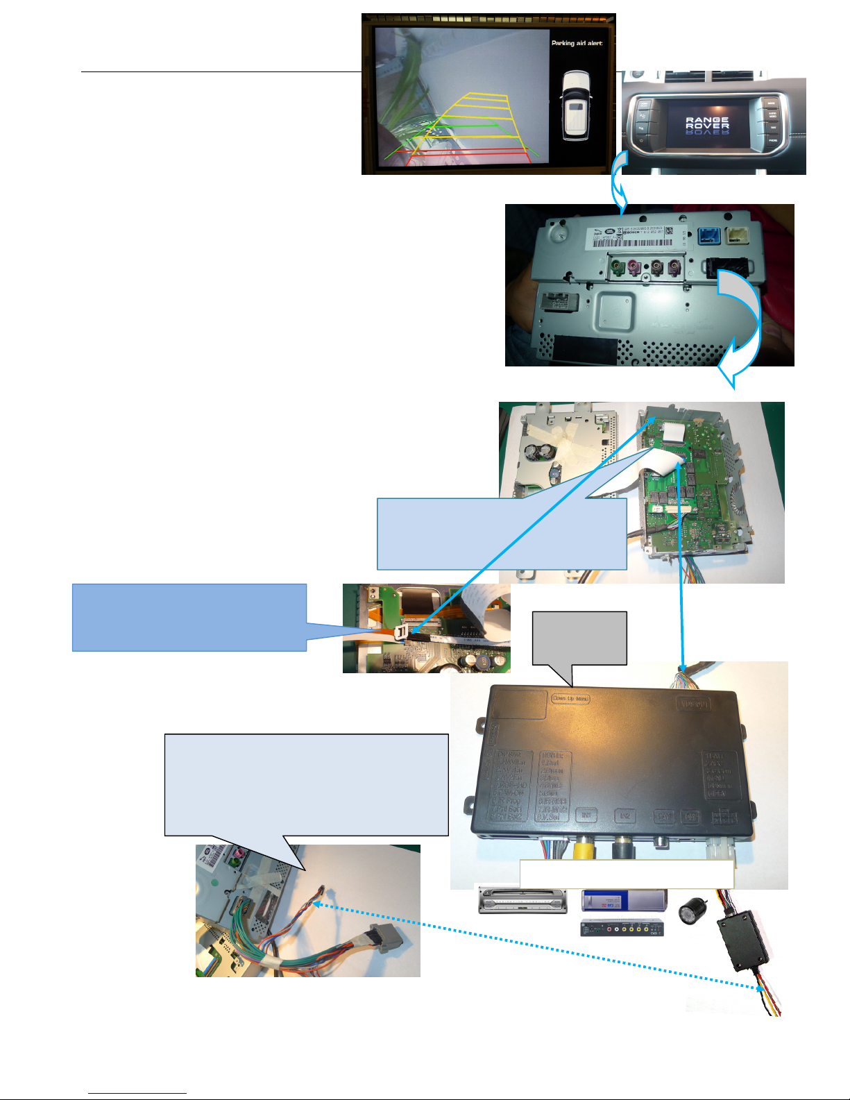
1.Systemconnection
Thedaughterboardisinstalledontheribbon
connectingthe2bigPCBsinside.3screwsareusedto
fixitthere.
TheCANboxwhichhasOEMplugandsocketcanbeinserted
ontheOEMpowerplugbehindmonitor,itcangenerateACC,
reversetriggersignal[bigcurrentwith12Vwhichisalsookto
supplyacamera],andMMIcontrolsignalstointerface.
NAVIAV1,AV2Rearview
3keysfor
colortuning.
The4Ptouchpanelconnectorshouldalsogo
throughthedaughterboardthustouchisgivento
theinstallednaviaswell.
2/5
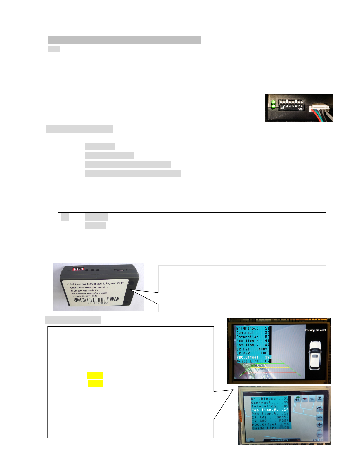
2.DIPswitchsetting:
DIP =ON[DIP=Downside.]=OFF
1RGBenabledRGBdisabled.
2,AV1forDVDenabledAV1disabled
3AV2forTunerorextravideoenabledAV2disabled
4RGB=HDRGB[800X480orVGA640X480]RGB=NormalNTSC[480X240]
5Thisisreversecameratriggerwire
gotoCAMwhenGreenwire=12V]
gotocarvideowhenGreenwire=12V
6IRprogrammewhenoncetoON
Tou chcalibrationwhengettoON>5times.
OFFfornormalwork.
7,87=UP:for8‐inchLCD,eg;Evoque
7=Down:for7‐inchLCD,eg;discovery4andJaguar.
DIP8:SetDOWNtoenablePDCdisplayedtogetherwithreversecamera.UP=forfullscreenreversevideo.
WhenDIPsetwrong,thescreenmayshownoiseorblackscreen[notdamageanything].
SetDIP7tocorrectpositionsince2typesofLCDneedsdifferenttiming.
3.InterfaceSettings
Thesignaldefinitionof6PoninterfacefromCANbox:
Yellow:constantpowerof12V。black:GNDofchassis。
RED[ACC]:whenthemonitorworks,thiswire=12V,otherwise=0V。
Green:reversesignalwire[=12Vwheninreverse],itcanbeused:
Togivereversesignaltointerfacebox,alsogivingpowertocamera[max.1A]
Whengivingpowertocamera,a100ucapacitorisnecessaryonthiswiretofilterthenoiseoncameralongwires.
Whenonlygivereversesignaltointerface,andcameraispoweredelsewhere,donotaddcapacitor。
Whitewire:switchsignalwire,when=12Vor5V,thisinterfaceswitches.
Graywire:CANbuscontroldatatointerface,itisusedtopopupthecontrolicons.Seenote2ontheendofthiswire.
The3sidekeysare:menu,+,‐ respectively.Whenmenuispressed,OSDstrings
willpopuponscreen,andtheinstallermayadjustthebestvideoeffect.The+/‐
willchangethevalue.
TheDVD/TUNER/NAVIistosettheIRcodeoutputtotheinstalleddevice,so
peopleuseoriginalknobtocontrol
Whensetto“none”,thecontroliconswillnotpopout
Whensetto“Prog”,theinstallercanuseDIP6=DowntoprogramtheIRcode
intotheinterface,soextranewdevicescanbecontrolled.
ThePositionH,PositionVareusedtosetthepicturelocationonmonitor.
PDCoffset:canbeusedtosetthePDCpicturecenteredontheright1/4 screen.
TheGuide.Lineoption:whensettoON,guidelinewillbedisplayedwhenin
reverse.
CANbox:
ONLYdip3Down=Rover
ONLYdip4Down=Jaguar
DIP34bothDown=EvoqueofRover
TheCANboxneedsre‐insertthe4PpowercordwhenDIPchanged.

3/5
4. Video switch among different inputs
Rover/Evoque:TheusermaypresstheMENUkeyanytimeto
switchtheinputsofinterface.
TheAmericanversionofEvoquewhichhasnonavi,peopleuse
theAudiokeytoswitch.
Theusermayalsouseextrakeypadtoswitchtheinputs,inthis
case,thewhitewireofthe6PwirebetweenCANboxand
interfaceshouldbecutoff.[suggested.]
Jaguar:userpressestheNAVkeytoswitchtheinput.Theyarrow
keyswillpopuptheMMIiconstocontroltheinstalleddevice.
Forthedual‐view,peoplecanpressthedual‐viewbuttontoswitch.1/2 ”
thereverseswitch.
TheprogrammingofIRcode:
Thereare>10typesofDVD,NAVI,andTuners’IRcodearestoredinsidetheinterface.Theinstallerjustadjuststheoptionstoselectto
wantedone,thenitworks.Ifthewantedtypeisnotthere,hemaysettheoptiontobe“Prog”inthemenutoprogramtheinterfaceto
replacenewremotecontrollers.
1) Whenprogramming,switchtheinputtoAV1,andsetDIP6downonce,thenthecontroliconswillbeshown,andoneofthethemwill
beblinking,whichmeanstheinterfaceiswaitingforanIRcode.TheninputonewantedIRcodebyusingthegraywireofthepower
connector.[connectingthegraywireinsidethepowerconnectortotheDVDorTV’ssignalwireinsidetheirsensor.Thereareusually3
wiresinsidetheirsensor:+5V,GND,IRsignal.]
2) Whenoneircodeissenttotheinterface,theblinkingiconwillbemovedtothenextone.Whichmeansonecodeisprogrammed.
Repeatthisstepuntilalliconsareprogrammed.
3) TheprogrammingofAV2isthesameasabove.
Wheninnormaluse,pleasedisconnecttheIRsensor’ssignalwirefromthegraywireinpowerconnector,butreconnectittothegray‐wire‐in
RGBconnector.Thepin7markedwithIR‐AV1/2.ThisistheIRoutputwire.
Whenpictureisshownlikethis,theinstallerneedstodo:
1. CheckDIP7=Up(8‐inch)orDown(7‐inch),wrongsettingswillmakethe
picturehasbigshiftinHorizontalandverticaldirection.
2. Changethe“POSITIONH”value,sotheleftsideofpicturewillbedisplay
accordingtoscreenleftedge.
3. Changethe“PDCoffset”valuetomovethePDCobstacleshowcentered.
4. TheDIP8shouldbesettoDOWN=enablePDCobstacleshowinreverse.
TheOEMPDCobstaclepicturewill
bedisplayedtogetherwithreverse
videowhenDIP8=DOWN.
The“PDCoffset”optionwillmakeit
centeredontheright1/4 screen.

4/5
Theinstallerdoesnotneedtowireanothertriggersignalforreverse.TheCANboxwilldelivera12Vvoltonthegreenwire,whichisusedto
triggertheinterfacealsopowerupacamera.[max1A].thegraywirewillcarrytheguidelinevaluetotheinterface.
touch to external NAVI:
5. CTRL port
Thereisa8‐pinextraCTRLportontheinterface,whichthe
installerdoesnotneedtouseinnormalsituation.Forexperienced
users,thisportmaybeusedtogetextrafunctions.
Onededicateddaughterboardcanbeused,sopeoplejusttouch
thescreen,theinstalleddevicescanbecontrolledbytheicons,
becausetheinterfacecangenerateIRcodebasedontouchscreen
operations.
theCTRLportcanbeconnectedtothelefttouchcable,soDVDandotherdevices
canbetouchcontrolled.Theinternalswitchmakesthenaviusetouchpanelwhenin
RGB‐input,andDVDusesthetouchpanelwheninAV1input.
Ctrlportsignaldefinitions:
Pin1,2+5Voutputvoltageforsound‐switch‐relay,whenAV1isselected=5V,0VwhenAV2selected.Max3A.
3:Constant+5VMax.2A
4,8Ground
5:Dedicated control bus for camera。ShouldnotbeconnectedtoGND,otherwiseCPUwillhalt.
6:
7+5Voutputwhenininterfacemode,0VwheninCarmode.
Note2:
Thereisagraywirebetweenthecanboxandinterfacebox,whichisusedtodelivercontroldata,sothatmultimediaiconswillpopoutandbe
executed.Thiswirecanalsodeliverterminal‐modecontroldata.Soa3rdpartycomputercancontrolthisinterface.[terminalmodelike:todirectlygoto
RGBinput,toAV1input,AV2input,reversecamerainput],togetthefullimplementationoffospinterfaceterminalmodeoperations,pleasecontact
fospsalespeople.
TotouchpanelTonavi
ToCTRLport
Allrover/JaguarcarshasanOEMtouchpanelondisplay,whichcanbe
switchedautomaticallytoexternalnavi。
Theinstallerneedstowirethe“PNL‐OUT”tothetouch‐panel.while
PCB‐IntothePCBsocket.Thedaughterboardhastherelaytoswitchthe4
touchsignalstogetherwithvideoswitch.

5/5
6.Parameters
No.nameparameter
1RGBvideoamplitude0.7Vppwith75ohmimpedance
NTSCresolution[400X240,480X240]ofnavigationisallowed.
AlsoHDnavi:800X480,640X480isallowed.
2syncamplitudeinRGB‐naviport3~5Vppwith5Kohmimpedance
SyncshouldbeNTSCcompositewithnegativepolarity.
3Av1,Av2,camvideoamplitude0.7Vppwith75ohmimpedance
4Av1,Av2,camstandardNTSC/PAL/SECAMautomaticswitch
5
6NormalworkPowerconsumption2.4W[0.2A@12V]
7Standbycurrent<5mA
8Standbystart10secondsaftertheusersswitchofftheCDunit.
9Reversetriggerthreshold>5Vtrigger
10Worktemperature‐40~+85C
11dimensions15.6X9.2X2.2Cm
Popular Automobile Electronic manuals by other brands


Dakota Digital
Dakota Digital LED Tail Lights LAT-NR421 installation instructions

Nav TV
Nav TV Genesis VIM XG installation instructions

Audiovox
Audiovox Advent PSD100 installation manual

HMS
HMS FRC-EP170 Hardware manual

Jacob Jensen
Jacob Jensen Electronic Parking Disc 3 user manual

KAP
KAP AD 4G Plus PAS-151112 instruction manual