manuals.online logo
Brands
  1. Home
  2. •
  3. Brands
  4. •
  5. CrimeStopper
  6. •
  7. Automobile Electronic
  8. •
  9. CrimeStopper CA-5014 User manual

CrimeStopper CA-5014 User manual

About the product
A Parking assist system uses ultrasonic sensors to monitor distances.It
electronically detects the area at the rear of your vehicle while
reversing, and alerts you with an audible tone/visual warning if there
is an obstacle behind your car.
This product features a self-test and learning function which is ideal
for cars with tow-bars, or with spare wheels located at the rear.
Each part of this product has passed rigorous testing before be-ing
released to the market and is reliable at a wide temperature range.
The unit is warranted for a limited period of time from the date of
purchase. In the unlikely event of a defect arising in this product
when used in accordance with the manufacturer's instructions, the
parts would be repaired or replaced free of charge.
Important notice
Disclaimer
The parking assist system is designed as a driver assistance device,
and should not be used as a substitute for safe parking practices.
You must constantly check the outside circumstance while parking.
The manufacturer does not guarantee or assume liability for collisions
or damage caused while parking your vehicle.
Parking sensors provide assistance while reversing. Driving skills,
such as slowing down, use of mirrors etc. are always essential.
1. This unit is for vehicles with 12V DC.
2. Unit should be installed by a professional auto technician.
3. Route wiring harness away from heat sources and electrical
components.
4. It is strongly recommended to check the position of the sensors
before the actual drilling of the holes.
5. Perform test after finishing the installation.
Manual
Parking assist
system
All rights reserved.
The right to change the design and specifications for improving the product is reserved.
CA-5014
MODEL:
Key features
Dual-color LED display with built-in buzzer
Intelligent detection, super for cars with spare tire or other protrusion
Anti-false alert technology
Self-test function
All weather design
Technical parameter:
Input voltage 9~16V DC
Beep volume 70 ~ 90 dB
Detection range 0.3m ~ 2.5m/1ft ~ 8.2ft
Sensor installation height 45cm ~ 60cm/1.5ft~2.1ft
LED display
Warning light & damaged
sensor location indication A B C D
LED indicator
Buzzer
Learning function for car with tow bars or spare wheel
Switch ignition on, engage and disengage reverse gear 10 times.
On the 10th time stay in reverse gear for 6 seconds while the kit
performs the learning function.
To clear the learning function switch ignition on, engage and disengage
reverse gear 12 times. On the 12th time stay in reverse gear for 8
seconds while the kit reverts to factory settings.
X10
+
1"
The display will flash and beep
once, this indicates that the
learning function is successful.
The system will no longer false
alarm because of a tow-bar or
spare wheel. Flash and beep once
Be
Self-test function
Be Be---Be --- Be---
When reverse gear is selected, the system will perform a self-test
procedure.
1.If no faults are detected after selftest, the buzzer will beep"once,
and the display will scan once.
2.If a faulty sensor is detected after selftest, the buzzer will beep
three times, and the display will show the faulty sensor location.
When the learning function is
activated, the system will ignore the
tow-bar or spare wheel and only detect
other objects behind the vehicle.
Note: If the vehicle does not have a tow-bar or spare wheel, you do not need to
use this function.
0.5 m/
1.64ft
Flash and beep once beep three times
Be
In "0" position (Factory Setting) In "20" position
Dual intelligent function for spare wheel
Sensor installation height choose
Sensor installation
55cm<H<65cm / 1.8ft<H<2.1ft
(Factory Setting)
Sensor installation
45cm<H<55cm / 1.5ft<H<1.8ft
0.50 m
1.6 ft
49cm/1.6ft
29cm/
0.95ft
In "0" position: The measured distance is between sensor and obstacle.
In "20" positon: The measured distance is between spare wheel (20
cm/0.65ft) and obstacle.
ECU
Be B e
GND
Red
Black
Reversing light
A
D
B
C
ABCD
ECU
Display
Sensor installationWire connection
How does the system work Attention
False detection may occur in the following situations:
After installation, please fully test the system before use.
Heavy rain, dirty or damaged sensor may cause false warning
occasionally.
Ensure that the self-test procedure is completed and all
sensors are functioning before reversing.
Do not wash the sensor with pressure
washer or swab them forcibly.
Please wash car with low-pressure
water.
Please melt the ice with warm water
when the sensors are covered by ice.
Please clean the sensors with cloth
or low-pressure water when the
sensors are covered by mud or snow.
Sensor maintenance
Troubleshooting
After installation, the display doesn’t work
a) Are all wires connected properly?
b) Is the vehicle’s ignition ON?
c) Is reverse gear engaged (the reverse light should be on)?
Damaged sensor detected
a) Are all sensors plugged into the ECU correctly and tightly?
b) Is the sensor wire broken or damaged?
c) Is the sensor covered by mud or snow?
d) Is the sensor damaged?
False warning
a) Are all sensors plugged into the ECU in the correct position tightly?
b) Does any sensor detect the ground?
If the problem persists, please follow these steps
a) For consumers: contact your dealer or nearby service centre
b) For installer or dealer:
1) Replace the ECU and recheck the system
2) Test the sensors with certified ECU by using a flat wooden board
3) Plug the certified sensors into the ECU and recheck
4) Email your question to us and we will reply ASAP
L
8
1L8
2L8
2L8
2L8
1L
45cm<H<65cm
Installation diagram
Display
Improper installation will result in
false alert
The sensor should be
installed vertically
Important notice: the sensor should be installed vertically, the
"up" sign must be on upside.
(1.5ft<H<2.1ft)
The sensors should
be installed vertically.
Cut the holes in the bumper
with the cutter provided Push the sensor into the
hole firmly.
Rear bumper
Use a pilot drill after meas-
uring to prevent the hole
cutter slipping.
<0.3m/1.0ft
0.3~0.59m/1.0~2.0ft
0.6~0.89m/2.0~3.0ft
Be
Warning
sound
Be----
Be---- Be -- --
Stage
Safe
Slow
Stop
Distance
7 rows
6 rows
5 rows
4 rows
3 rows
2 rows
1 row
0.9m~2.5m/3.0~8.4ft
No Beep
Be--Be -Be -
Function testing
Function test is possible by holding a wooden board (0.3mx1m)
standing at the back of the car, and slowly reverse the car to test
each function respectively as shown in this manual.
2.5m/8.
2
ft

Other CrimeStopper Automobile Electronic manuals

CrimeStopper CS-880 OEM User manual

CrimeStopper

CrimeStopper CS-880 OEM User manual

CrimeStopper BackStopper CA-5004 User manual

CrimeStopper

CrimeStopper BackStopper CA-5004 User manual

CrimeStopper BackStopper CA-5006 User manual

CrimeStopper

CrimeStopper BackStopper CA-5006 User manual

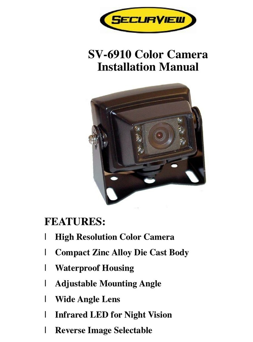
CrimeStopper SecurView SV-6910 User manual

CrimeStopper

CrimeStopper SecurView SV-6910 User manual

CrimeStopper Back Stopper CA-5012 User manual

CrimeStopper

CrimeStopper Back Stopper CA-5012 User manual

CrimeStopper B350C510-B(S) User manual

CrimeStopper

CrimeStopper B350C510-B(S) User manual

CrimeStopper SV-9154 User manual

CrimeStopper

CrimeStopper SV-9154 User manual

CrimeStopper BackStopper CA-5005 User manual

CrimeStopper

CrimeStopper BackStopper CA-5005 User manual

Popular Automobile Electronic manuals by other brands

PNI Escort P05 A user manual

PNI

PNI Escort P05 A user manual

Lippert ConnectAnywhere 2.0 All-in-One installation manual

Lippert

Lippert ConnectAnywhere 2.0 All-in-One installation manual

VDO SENDER UNIT 2159-20 datasheet

VDO

VDO SENDER UNIT 2159-20 datasheet

Waeco Magic Watch MWE-850-4DSM Installation and operating manual

Waeco

Waeco Magic Watch MWE-850-4DSM Installation and operating manual

BrandMotion Curb Alert Park View Pro 5000-CA6 installation instructions

BrandMotion

BrandMotion Curb Alert Park View Pro 5000-CA6 installation instructions

Audiovox CMT405 operating instructions

Audiovox

Audiovox CMT405 operating instructions

Directed Electronics VIPER 4103XV owner's guide

Directed Electronics

Directed Electronics VIPER 4103XV owner's guide

Axis APS400 installation manual

Axis

Axis APS400 installation manual

Xpresskit PKUCG2X installation guide

Xpresskit

Xpresskit PKUCG2X installation guide

ICP DAS USA DN-8368MB user manual

ICP DAS USA

ICP DAS USA DN-8368MB user manual

annke X4 installation manual

annke

annke X4 installation manual

Double Intelligence Technology PSA quick start guide

Double Intelligence Technology

Double Intelligence Technology PSA quick start guide

Voxx Electronics ACA101D Installation  & owners guide

Voxx Electronics

Voxx Electronics ACA101D Installation & owners guide

Nav TV NTV-KIT873 instruction manual

Nav TV

Nav TV NTV-KIT873 instruction manual

Adaptiv Adaptiv Mini FITTING & USER GUIDE

Adaptiv

Adaptiv Adaptiv Mini FITTING & USER GUIDE

PerTronix Ignitor II instructions

PerTronix

PerTronix Ignitor II instructions

Renault 8201373014 installation instructions

Renault

Renault 8201373014 installation instructions

Honeywell Thor VM2 reference guide

Honeywell

Honeywell Thor VM2 reference guide

manuals.online logo
manuals.online logoBrands
  • About & Mission
  • Contact us
  • Privacy Policy
  • Terms and Conditions

Copyright 2025 Manuals.Online. All Rights Reserved.