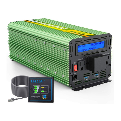
EDECOA DPP10 User manual

COPYRIGHT©EDECOA, ALL RIGHT RESERVED,PSW-USA-Rev2.71
1 / 17
USER MANUAL
Model:
DPP10 DPP15
DPP20 DPP25
DPP35
Language: English

COPYRIGHT©EDECOA, ALL RIGHT RESERVED,PSW-USA-Rev2.71
2 / 17
ENGLISH
1. What is the power inverter?.............................................................................................................................................. 3
2. Inverter appearance description........................................................................................................................................ 3
3. Intended use.......................................................................................................................................................................4
4. Installation......................................................................................................................................................................... 4
5. Opening the device............................................................................................................................................................5
6. Connection.........................................................................................................................................................................5
7. About the remote controller.............................................................................................................................................. 7
8. Service environment..........................................................................................................................................................9
9. Technical data:(Pure sine wave).................................................................................................................................. 9
10. How to select the proper inverter you need?................................................................................................................. 9
11. How to choose the proper cable?.................................................................................................................................. 10
12. Batteries using time.......................................................................................................................................................11
13. How to connect two or more batteries?........................................................................................................................ 12
14. Protection features.........................................................................................................................................................12
15. Problem Causes............................................................................................................................................................. 12
16. How many watts do you need?..................................................................................................................................... 14
17. Do i need modifed wave or pure sine wave i nverter?..................................................................................................15
18. What is an over current protection device and why do you need one.......................................................................... 15
19. Special use.....................................................................................................................................................................16
20. Improper use of power inverter.....................................................................................................................................16
21. Disposal......................................................................................................................................................................... 16
22. Warranty........................................................................................................................................................................ 17
23. Compensation................................................................................................................................................................17

COPYRIGHT©EDECOA, ALL RIGHT RESERVED,PSW-USA-Rev2.71
3 / 17
1.WHAT IS THE POWER INVERTER?
The power inverter converts direct-current (DC) low voltage (12V model, 24Vmodel ,48V model) power to 120V
alternating-current (AC) that you can use to operate all kinds of devices, like kitchen appliances, microwave, air
conditioner, TV, computer or work tools. You just connect the battery and devices to the inverter.Then you've got
portable power. It is simple and you can use it anywhere, anytime, you will always be able to run your devices from
battery.
2.INVERTER APPEA RANC E DESCRIPTION
Pure Sine wave Inverter 1000-2000W
Pure Sine wave Inverter 2500W
Pure Sine wave Inverter 3500W

COPYRIGHT©EDECOA, ALL RIGHT RESERVED,PSW-USA-Rev2.71
4 / 17
①LCD Display
②Outlets:15A/120VAC
③Power ON/OFF Switch
④AC Output : 3P Terminals
⑤Remote Control Port
⑥Dual USB Charging
⑦GND Terminal
⑧Battery input -
⑨Battery input +
⑩Fans
⑪ LED Status Display
3.INTENDED USE
This inverter is used to convert low voltage (Direct Current-DC) into alternating voltage of 120VAC, for example, from
battery (preferably deep-cycle) or in photovoltaic-island systems.
A very simple way to use an inverter for emergency power (such as during a power outage), is to use a car battery (with
the engine running), and an extension cord running into the house, where you can then plug in electrical appliances.
Please use the inverter according to the following instruction and in accordance with the standards and guidelines
applicable locally. Any other use may cause injury or property damage. These inverters are not suitable for the supply of
life support and / or medical equipment. The inverters are no Uninterruptible Power Supply!
4.INSTALLATION
4.1Caution: IMPORTANT NOTICE PRIOR TO USING
Do not install the inverter on flammable building materials.
Do not install the inverter in areas where flammable or explosive materials are stored.
The inverter must only be installed by sufficient trained personnel in compliance with local safety regulations.
When the inverter is running, the temperature of the chassis and the heat sink can be high. Do not install the inverter in
locations where it can be inadvertently touched.
Ambient temperature should be kept below 50 ℃, to ensure the best inverter operating conditions, and extend its
service life.
Inverter should be installed in a well-ventilated environment to ensure good heat dissipation.
Avoid placing the inverter in direct sunlight, rain and snow. This can extend the life of the inverter. It is advisable to
select the installation site with occlusion but ensure proper air-circulation.
Inverter protection class IP65, indoor and outdoor environment can be used.
The mounting method and position must be suitable for the weight and dimensions of the inverter, please refer to the
technical data.
4.1.1CHECKING ACCESSORIES
After unpacking the inverter package, check that the delivery unit is complete and that there is no visible external damage.
If any items are missing or if there is any damage, contact your dealer.
Check that the package contains the deliveries as listed below:
1) Power Inverter ×1
2) One pair of screw cap (Red and Black)

COPYRIGHT©EDECOA, ALL RIGHT RESERVED,PSW-USA-Rev2.71
5 / 17
3) One pair of DC input terminal ring (For backup ,Some models)
4) User manual ×1
5) Ground Cable×1
6) Battery cable
7) Remote controller and connecting cable
8) Spare fuse (Some models)
You need to choose the appropriate location to install the inverter to ensure that the inverter can work properly and
efficiently.
4.2Install carrier requirements
The inverter mounting carrier must be fire-resistant.
Do not install the inverter on flammable building materials.
Please ensure that the mounting surface is strong enough to meet the load requirements of the inverter.
In a residential area, do not install the inverter on a plasterboard wall or similar sound-poor wall to avoid
interference with the noise in the work area.
4.3Installation requirements:
Install it vertically or tilt it back up to 15 ° to allow the fan to cool the machine.
Figure 3-1Proper installation Figure 3-2 Installation Space (Unit: inch)
Do not install the inverter in an inclined position (forward, backward, overturned), horizontally mounted or inverted.
4.4Installation space requirements
It is recommended that the inverter be mounted at an adequate height for easy operation and subsequent
maintenance.
When installing the inverter, make sure that there is enough space around the inverter to ensure adequate installation
and cooling space, as shown in Figure 3-2.
5.OPENIN G THE DEV ICE
Non-professional personnel must not open the inverter as there is high voltage inside. Before opening the device, please
remove cables of both DC and AC sides, turn on the switch and leave the inverter alone for 1 hour.
6.CONNECTION
6.1 Battery connection
1.Please read the manual carefully and install the inverter properly. If you have questions, please contact our service team.
It may cause damage to the inverter or cause injury if you do not act in accordance with the instructions from the
manual.
2.Set the switch to the "OFF" position when connecting the inverter to the power source. The energy source may be a
battery or other stable DC power supply.It must be ensured that the DC voltage of the power source is matched to the
rated DC voltage of the inverter. Higher voltages can cause damage the inverter.

COPYRIGHT©EDECOA, ALL RIGHT RESERVED,PSW-USA-Rev2.71
6 / 17
3.The load power should not exceed the rated power of the inverter.
The two DC-input connectors of the inverter are color-coded:
The red terminal for the positive pole (+) The black terminal for the negative pole (-).
Inverter DC input installation method:
Please fix the battery cables on the positive and negative terminals of the inverter tightly. Otherwise, there will be
large current which will result in severe heating problem and parts damaged.
6.2 Load connection
1.Connect your device into power inverter AC outlet. (Make sure your device’s rated power is less than the inverter’s,
and the working voltage is 120VAC±5%)
2.The connections between power source (battery) and inverter cable terminals must be securely mounted.
3.Set the switch to the "ON" position
Tips:
The battery must be able to deliver necessary amperage according to the power of the inverter and load. For example,
for a 24v inverter to drive 1000W resistive load, the battery should be able to provide more than 45 amps! (On a 12V
inverter it will be >90 amps!)
Please do not connect the AC output side to other power source (i.e. electric supply) as this is not a grid interactive
inverter.
The cover should be connected to protective ground before usage. Please switch off the inverter and only on as
necessary to avoid power consumption from the batteries without load when it is not being used.
Use the supplied cable from the manufacturer or at least those with the same or larger cross-section.
Keep these connections as short as possible, it will flow considerable current depending on power extraction!
The inverter should be installed in a dry and well-ventilated area. The air inlet may not be blocked, and it should be kept
20cm away from the wall.
Do not install the inverter near flammable or explosive material. Please use dry cloth to clean the inverter. Do not stack
multiple inverters in operation above another so as the cooling is not guaranteed.
6.3 Grounding wire installation:
The connection method of the ground wire is different based on the different using environment (vehicle, boat, home,
outdoors) . You could find where to connect the ground cable in the power inverter following that icon “ ”
When using the power inverter in a vehicle, please connect the ground wire to the chassis of the vehicle.

COPYRIGHT©EDECOA, ALL RIGHT RESERVED,PSW-USA-Rev2.71
7 / 17
When using the power inverter on a boat, please connect it to the boat's ground system.
When using the power inverter at home, please connect it to the home ground wire system. If there is no ground wire
system at home, please connect it to the negative terminal of the battery.
When using the power inverter outdoors, please connect it to the negative terminal of the battery. It will not affect the
normal working of the power inverter without connecting the ground wire.
6.4 GFCI breaker or GFCI Outlet installation and GFCI Receptacle Tester
Electronic experience required. Please contact our customer service team for a detailed introduction.
6.5 Please pay attention when the power inverter works for the main power system in RV or at home
When the power inverter is connected to the RV power system or home power system for power supply, the
inverter could be damaged If the shore power or alternator is connected at the same time by mistake when the power
inverter is working. The AC input voltage is not accepted by the power inverter.
To prevent this case, we recommend installing a Dual Power Automatic Transfer Switch (ATS).
The ATS mainly used for testing whether normal(N) or spare(R) power is normal or not. Here is the compatible
specification:
12P;
2120V/60HZ;
3Travel switch includes shutdown function
ON (R )-OFF-ON(N), Here is the schematic diagram of RV power system.
Note:
The ATS must contain an intermediate disconnect setting to prevent the generator or grid from being connecting at the
same time as the inverter, resulting in the inverter being burnt.
The switching time of the ATS is 1-2s, and the electrical device will stop working in a short time.
7.ABOUT THE REMOTE CON TROLLER
Tips: The switch of the remote control and the switch of the inverter is parallel.
Therefore, when any one controls the inverter, the other switch must keep the "OFF" state.
According to different models, we have two models of remote control (ED-RC, ET-RC). However, it is not possible to
replace each other.

COPYRIGHT©EDECOA, ALL RIGHT RESERVED,PSW-USA-Rev2.71
8 / 17
ED-RC remote controller
1.ON/OFF switch
2.Status light: If it is green, it means the inverter is on. If it is off, then the inverter is off.
3.Low input voltage indicator light: If the DC input voltage of the inverter is too low, it will be yellow
4.Battery power indicator light:
If DC voltage ≥12.5V, 4 LED lights will be green
If 12V≤DC voltage≤12.5V, 3 LED lamps will be green
If 10.8V≤DC voltage≤12V, 2 LED lamps will be green
If 10V≤DC voltage≤10.8V only 1 LED lamp will be green
Note: If your inverter is 24v, please multiply the above DC input voltage by 2.
About ED-RC remote cable
ED-RC remote cable is 6.5ft or 13ft long standard RJ45 network cable, it is easy for you to extend the length of it. When
working, the voltage drop through this 6.5ft cable is about 0.02V, you can ignore it. If it is a 33ft long cable, the voltage
drop will be about 0.1V. If you use very long remote cable, please note that the battery power indicator light maybe not
correct.
If the remote cable has problem, it may cause the following problems:
1.The inverter can’t be turned ON/OFF by the remote controller, only the battery power indicator light works.
2.After connecting the remote controller, the inverter will be always on, the inverter can’t be turned off, the battery
power indicator light can’t indicate the actual power.
3.After connecting the remote cable, the inverter will be always on, all LED lights on the remote controller are off, the
inverter can’t be turned off.
4.After connecting the remote controller, all LED lights on the remote controller are off, the inverter can’t be turn on.
5.After connecting the remote controller, the status light sometimes work, sometimes not, the inverter maybe turn off
automatically.
Note: If the remote controller can’t work properly, please try to replace the remote cable first.
ET-RC remote controller

COPYRIGHT©EDECOA, ALL RIGHT RESERVED,PSW-USA-Rev2.71
9 / 17
1. ON/OFF switch(press 3s),Backlight switch(press once)
2. LCD display
3. USB charging: 5VDC/2.1A * 2
About ET-RC remote cable
ET-RC remote cable is 13ft long standard RJ45 network cable,In order not to affect the display signal transmission, it is
recommended to use network lines within 16.5ft.
Note: If the remote controller can’t work properly, please try to replace the remote cable first.
8. SERVICE ENVIRONMENT
Ambient temperature: -20~+50℃
Storage temperature: -40~+85℃
Relative humidity: 0~85% Non-condensing
9.TEC HN IC AL DAT A: (PURE SIN E WAVE )

COPYRIGHT©EDECOA, ALL RIGHT RESERVED,PSW-USA-Rev2.71
10 / 17
10. HOW TO SEL ECT THE PROPER IN VERTE R YOU NEED?
Dependent of the devices you want to operate, you must pay attention in the wattage of each device and calculate the
total watts. We recommend you to buy an inverter higher than the power you think you need – good practice is around
30% - 50% more.
For example:
We recommend you to buy the power inverter 1500w. We should give some thought to a larger one, as there will likely be
a time when you wish you'd bought a bigger model... in this example, you might decide you'd like to run a fan while you
compute, or let the kids watch TV.
Sometimes devices like a motor, it need more power at start-up (peak power) although after the motor is running use
continuous power. This is important to consider. For example, an air conditioner, refrigerator may need startup-
powerfrom 3 to 7 times of the continuous power. The best procedure is to find out about the current requirement of the
device to be connected to the inverter. Normally this information is in the device specifications.
What is meant by the terms "continuous-2000 watts" and "peak surge-4000 watts" is that some appliances or tools, such
as ones with a motor, require an initial surge of power to start up ("starting load" or "peak load"). Once started, the tool
or appliance requires less power to continue to operate ("continuous load")
Example:
If you have a refrigerator with a continuous load of 3 amps and a start-up load of 8 amps:
3 amps x 120 volts = 360 watts continuous
8 amps x 120 volts = 960 watts continuous
In this case you should use an inverter with 1500W.
11 . HOW TO CHOOSE THE PROPER CABLE?
Inverters should be attached directly to the battery. The wire size depends on the distance between the battery and
inverter.
The following is a reference to the cable size of the battery recommended by the DC12V system inverter. (DC24V system
inverter Cable Section Area /2)
800W continuous load
1 – 3ft Cable 7AWG
3.5 – 5ft Cable 6AWG
5.5 – 13ft Cable 4AWG
1000W continuous load
1 – 3ft Cable 6AWG
3.5 – 5ft Cable 5AWG
5.5 – 13ft Cable 3AWG
1200W continuous load
1– 3ft Cable 5AWG
3.5 – 5ft Cable 4AWG
5.5 – 13ft Cable 3AWG
1500W continuous load
1 – 3ft Cable 5AWG
3.5 – 5ft Cable 4AWG
5.5 – 13ft Cable 2AWG
2000W continuous load
1 – 3ft Cable 5AWG
3.5 – 5ft Cable 2AWG
5.5 – 13ft Cable 1/0AWG
2500W continuous load
1 – 3ft Cable 3AWG
3.5 – 5ft Cable 2AWG
5.5 – 13ft Cable 2*2AWG
3000W continuous load
1 – 3ft Cable 3AWG
3.5 – 5ft Cable 0AWG
5.5 – 13ft Cable 2/0AWG
3500W continuous load
1 – 3ft Cable 2AWG
3.5 – 5ft Cable 0AWG
5.5 – 13ft Cable 2*1AWG
5000W continuous load
1 – 3ft Cable 2/0AWG
3.5 – 5ft Cable 2*1AWG
>5ft Not recommended

COPYRIGHT©EDECOA, ALL RIGHT RESERVED,PSW-USA-Rev2.71
11 / 17
12 . BATTERIES USING TIME
You can calculate that the storage battery’s use-time by this formula:
푈푠푖푛푔푇푖푚푒 퐻표푢푟푠 = 퐵푎푡푡푒푟푦퐶푎푝푎푏푖푙푖푡푦 퐴퐻
푙표푎푑푔푒푛푒푟푎푙 푝표푤푒푟(푊) 0.85/퐵푎푡푡푒푟푦voltage(V)
Attention:
If batteries of the same size are connected in parallel, the time is multiplied by the number of parallel batteries. For
example, four 12V 60AH batteries are connected in parallel, and 500W of load can be used continuously for 1 h 12
min*4=4 h 48 min
The above is the time that can be used when the new battery is fully charged. If it is an old battery, use it for more than
half a year and multiply it by 0.8. The battery has been used for more than one year. It needs to multiply the usage time by
0.5. For example, a 12V 100A battery has been used for half a year. If a 1000W load is used, it can be used continuously for
1h*0.8=48 min.
Tip: Use the inverter in your car. Engine start batteries should not be discharged below 90% charged state, and marine
deep cycle batteries should not be discharged below 50% charged state. Doing so will shorten the life of the battery based
on most battery manufacturers recommendations.
Note: If you intend to use power tools for commercial use, or any load of 200W for more than 1 hour regularly (between
battery recharging) we recommend installing an auxiliary battery to provide power to the inverter. This battery should be
a deep cycle type and sized to meet your run time expectations with the engine off. The auxiliary battery should be
connected to the alternator through an isolator module to prevent the inverter from discharging the engine start battery
when the engine is off.

COPYRIGHT©EDECOA, ALL RIGHT RESERVED,PSW-USA-Rev2.71
12 / 17
13. HOW TO CONNE CT TWO OR MORE BATTERI ES?
Parallel connected = same voltage doubled AH (TWO 12V batteries connect in paralleled will provide 12V output but
double the using time)
Connected in series = double voltage same AH (Two 12V batteries connect in series will provide 24V output)
14. PROTEC TIO N FEATUR ES
Low voltage Protection:when the battery is in discharged condition, the inverter will shut down, at the same time, an
alarm will sound and the indicator light will turn on.
Over-voltage protection: when the input voltage exceeds rated voltage, the inverter will shut down, at the same time,
an alarm will sound and the indicator light will turn on. A substantial excess of the rated voltage, for example, at 48V on a
24V inverter will destroy the inverter!
Reverse polarity protection: when the inverter is connected reversely, inverter’s fuse will blow out to protect the
inverter. The DC input side with MOSFET protection will not work.
You have to replace all burnt fuses.
Over-load protection:when the continuous draw exceeds rated Watts, the inverter will shut down, at the same time,
an alarm will sound and the indicator light will turn on.
Short circuit protection: when the output side is short circuited, the inverter will shut down, an alarm will sound and
the indicator light will turn on.
Temperature control: If the temperature in the unite reaches 45°C the fan will start and cool down the device.
Over-temperature protection:when the inside temperature is over 75°C, the inverter will shut down, an alarm will
sound and the indicator light will turn on.
15.PR OBLEM CAUSES
PROBLEM POSSIBLE CAUSE SOLUTION
The inverter is ON but the LED
does not work. No response. No
alarm
Open circuit.
No DC input.
Fuse faulty.
1.Check entry circuit continuity
2.Check that the battery fuse is right.
3.Check all circuit connections are correct.
4.Check the ON/OFF button wiring.
The inverter is switched on and
the LED works. No AC output.
No alarm.
Reversed of polarity
connection on input side and
internal fuses have been
burnt.
1. Check and correct the polarity of input connections
and replace the internal fuse. (NOTE: Reversing the
polarity may cause irreversible damage to the fuse
circuit)

COPYRIGHT©EDECOA, ALL RIGHT RESERVED,PSW-USA-Rev2.71
13 / 17
Unusual Low output AC voltage Poor battery. Internal
MOSFET faulty.
Drive circuit faulty.
1.Reverse the potentiometer on drive panel to get
right output voltage.
2.Ensure the battery is enough and full.
3.Contact the technical support.
The alarm sounds 1 time per
time, after 2 seconds, same
beeps again.
The input voltage is very low.
DC12V inverter: 10-10.5V
DC24V inverter: 20-21V
1.Ensure the battery is enough and full.
2.Check that the battery cables are suitable for
transporting the DC voltage. Use a thicker or
shorter cable.
3.Setting DC input circuit connections.
4.The inverter loads the electrical power exceeding
the power provided by the battery, increasing the
battery specification.
The alarm sounds 2 times per
time, after 2 seconds, same
beeps again.
The input voltage is too low
and the inverter stop
working.
1.Ensure the battery is enough and full.
2.Check that the battery cables are suitable for
transporting the DC voltage. Use a thicker or
shorter cable.
4.The inverter loads the electrical power exceeding
the power provided by the battery, increasing the
battery specification.
The alarm sounds 3 times per
time, after 2 seconds, same
beeps again.
The input voltage is too high.
DC12 inverter: higher than
15.5V;DC24V inverter: higher
than 30V
1.Check that the voltage at the input DC terminals
does not exceed 15V/30V.
2.Check that we are not using a panel or wind turbine
not regulated for battery charging,Make sure
that the maximum voltage of the battery
controller does not supply voltages higher than
15V/30V.
The alarm sounds 5 times per
time, after 2 seconds, same
beeps again.
(The alarm is beeping
repeatedly)
The load AC exceeds the
nominal power by 120%.
Short circuit in connection.
1.The starting power of the electrical equipment is too
high and it is confirmed whether the starting
power of the electrical appliance exceeds the
maximum continuous power of the inverter.
2.Reduce load.
3.Disconnect the electrical outlet from the inverter
output outlet and restart the inverter. If you are
working normally, you need to check whether
there is a short circuit in the connected load
appliance or line.
The alarm sounds 4 times per
time, after 2 seconds, same
beeps again.
Inverter overheating 1.Check that the fan is working correctly, Try again
when the inverter has been cool down.
2.Keep the inverter in good ventilation and heat
dissipation.
Got 60VAC or so while testing
inverter's ground wire and
Neutral line ?
This voltage is an
electromagnetic induction
voltage, there is no current
leakage.
This is normal. Inverter output communication does
not distinguish hotline and neutral line, if you need to
distinguish the hotline and neutral line, please contact
customer service or after-sales technology.

COPYRIGHT©EDECOA, ALL RIGHT RESERVED,PSW-USA-Rev2.71
14 / 17
16. HOW MANY WATT S DO YOU NEED ?
To select an inverter that has enough power for your application,add the watts for items you may want to run at the same
time. Use the total wattage, plus 20%, as your minimum power requirement.
Note: The wattage's given below are estimates. The actual wattage required for your appliances may differ from those
listed.Check the nameplate on the appliance to determine the actual wattage required.
* Appliances and tools with induction motors (marked * in tables)may require from 3 to 7 times the listed wattage when
starting.The start-up load of the appliance or tool determines whether an inverter has the capability to power it. Be sure
to check the specific wattage requirements and operating instructions for appliances / tools to be used. Also, air
conditioners are a very difficult load because of the high start-up surge. Use the Locked Rotor Amps to determine the start
up surge requirement.
Appliances Estimated Watts Appliances Estimated Watts
Coffee Maker 600-1200 Household Fan 50-120
Keurig 1500 (max) 200-400
(continuous)
Clock Radio 10-50
Blender
300-1000
Stereo
30-100
Microwave(600-1000
Watt Cooking Power)
1000-2000 Phone Charger 10
Waffle Iron 800-1500 Laptop Computer 20-75
Hot Plate 750-1500 Mac Book Pro 85
Electric Skillet 1000-1500 iPad/ Tablet 10-20
Toaster Oven 1200 Desktop with Monitor 200-400
Toaster 800-1500 Inkjet Printer 15-75
Hair Dryer 1000-1875 Laser Printer 2000 (peak)
Clothes Iron 1000-1500 Photographic Strobe (300 Watt-Second)1200
(peak)
* Refrigerator 500-750 Aquarium 50-1000
* Chest Freezer 600 TV32" LED/LCD 50
* Washing Machine 500-1000 TV42" Plasma 240
Furnace Fan 750-1200
Appliances Estimated Watts Appliances Estimated Watts
Angle Grinder 900 Circular Saw 1400-1800
Drill (1/4"-1/2") 500-960 Chop/Cut OffSaw 1500-1800
Disc Sander 1200 Shop Vac6.5hp 1440
Jig Saw 300-700 * Electric Chain Saw14" 1200
Band Saw 700-1200 * Airless Sprayer 1/2 hp 750
Table Saw 1800 * Air Compressor 1 hp 2000
Pumps and Air
Conditioners
Estimated Watts Pumps and Air
Conditioners
Estimated Watts
* Well Pump 1/3 hp 750 (Running) 1400-
3000 (Starting)
* Sump Pump 1/2 hp 1050 (Running)
2150-4100 (Starting)
* Well Pump 1/2 hp 1000 (Running)
2100-4000
(Starting)
*Air Conditioner
(700
BTU
to
10,000
BTU)
1000-1500 (Running)
2200-5000
(Starting)
* Sump Pump 1/3 hp 800 (Running)
1300-2900
(Starting)

COPYRIGHT©EDECOA, ALL RIGHT RESERVED,PSW-USA-Rev2.71
15 / 17
17. DO I NEED MODIFED WAVE OR PURE SINE WA VE IN VERTER?
Advantages of Pure Sine Wave inverters over modified sine wave inverters:
a) Output voltage wave form is pure sine wave with very low harmonic distortion and clean power like utility-supplied
electricity.
b) Inductive loads like microwave ovens and motors run faster,
c) Reduces audible and electrical noise in fans, fluorescent lights,audio amplifiers, TV, Game consoles, Fax, and answering
machines.
d)Prevents crashes in computers, weird print out, and glitches and noise in monitors.
e)Reliably powers the following devices that will normally notwork with modified sine wave inverters:
•Laser printer, photocopiers
•Certain laptop computers (you should check with your manufacturer)
•Some fluorescent lights with electronic ballasts
•Power tools employing "solid state" power or variable speed control
•Some battery chargers for cordless tools
•Some new furnaces and pellet stoves with microprocessor control
•Digital clocks with radios
•Sewing machines with speed/microprocessor control
•X-10 home automation system
•Medical equipment such as oxygen concentrators
Modified Sine Wave works well for most uses, and is the most common type of inverter on the market, as well as the most
economical. Pure Sine Wave inverters (also called True Sine Wave) are more suited for sensitive electrical or electronic
items such as laptop computers, stereos, laser printers, certain specialized applications such as medical equipment, a
pellet stove with an internal computer, digital clocks, bread makers withmulti-stage timers, and variable speed or
rechargeable tools (see" Appliance Cautions"). If you wish to use those items with an inverter, then choose a Pure Sine
Wave inverter. If you mostly want to run lights, TV, microwave oven, tools, etc, a Modified Sine Wave inverter is fine for
your needs.
We often are asked if computers will work with Modified Sine Wave. It's been our experience that most (with the
exception of some laptops) will work (though some monitors will have interference such as lines or a hum). However, if
you have any doubt about any appliance, tool or device, particularly laptop computers and medical equipment such as
oxygen concentrators, we recommend that you check with its manufacturer to be sure it is compatible with a Modified
Sine Wave inverter. If it is not, choose one of our Pure Sine Inverters instead.
The difference between them is the Pure Sine Wave inverter produces a better and cleaner current. They are also
considerably more expensive. You might find it practical to get as mall Pure Sine Wave inverter for any "special need" you
may have, and also a larger Modified Sine Wave inverter for the rest of your applications.
18. WHAT IS AN OVER CURRENT PR OT ECTION DEV ICE AND WHY DO YOU NEE D ONE
Batteries are capable of supplying large amounts of current, and thousands of amperes could be present if a short circuit
were to occur. A short circuit can damage your system, cause a fire and be hazardous to your health. Incorporating an
over current device is an effective line of defense against a short circuit occurrence.
An over current protection device is typically a fuse or circuit breaker that goes inline on the positive cable, between the
inverter and battery, to protect your system. A fast-acting fuse or circuit breaker will blow within milliseconds under short
circuit conditions, preventing any damage or hazards.

COPYRIGHT©EDECOA, ALL RIGHT RESERVED,PSW-USA-Rev2.71
16 / 17
It is important to appropriately size your fuse or circuit breaker for both your inverter and cables. An oversized fuse could
result in cables exceeding their ampere capability, resulting in the cables becoming red-hot and dangerous. Consult your
owners1for the recommended sized fuse or circuit breaker and gauge for a safe installation.
19 . SPECIAL USE
Operating a Microwave with a Power Inverter
The power rating used with microwave ovens is the "cooking power" which refers to the power being "delivered" to the
food being cooked. The actual operating power requirement rating is higher than the cooking power rating (for example, a
microwave with "advertised" rating of 600 watts usually corresponds to almost 1100 watts of power consumption). The
actual power consumption is usually stated on the back of the microwave. If the operating power requirement cannot be
found on the back of the microwave, check the owner's manual or contact them anufacturer.
Operating a Photographic Strobe with a Power Inverter
A photographic strobe or flash generally requires a pure sine wave inverter capable of surging to at least 4 times the Watt
Se crating of the strobe. For instance, a strobe rated at 300 watts requires an inverter capable of surging to 1200 watts or
more.
Operating a Laser Printer with a Power Inverter
A laser printer generally requires a pure sine wave inverter capable of surging at least 6.5 times the maximum wattage
rating of the printer. For instance, a laser printer rated at 500 watts requires an inverter with a surge rating of at least
3,250 watts.
An inkjet printer does not maintain the same requirements as a Laser printer. Inkjet printers can be operated normally
with a modified sine wave inverter rated to handle the printer’s wattage requirement.
20. IMPR OP ER USE OF POWER INVE RTER
1. Reverse polarity: For the models which have reverse polarity protection, inverter's fuse will blow out to protect the
other part inside the inverter when the inverter is connected reversed. It is possible to damage the part of the positive and
negative terminals due to high current after a short circuit. It will not affect the normal use after changing the fuse. For the
model which is not equipped with reverse polarity protection, it is possible that the electrolytic capacitor and the MOSFET
will burn out. When this occurs, a crack sound can be heard and smoke will be seen coming out.
2. When the input voltage exceeds the allowable voltage range of the inverter, the electrolytic capacitor inside the
inverter will burn out. In this case, a crack sound can be heard and smoke will be seen coming out.
3. Heavy overload. The overload protection power of the inverter is 10% higher than the rated Watts, mainly used to
start some appliances which require high start current. It doesn't support a long-term use. If customer uses the inverter
for long period of overload, it may cause aging of electronic parts and rapid increase of machine temperature. In more
serious cases, the electrolytic capacitor inside the inverter will burn out. If so, a crack sound can be heard and smoke will
be seen coming out.
4. The power inverter is used outdoor during rainy days or when water gets into the inverter. Because the inverter is
not waterproof, water entering any electronic part will cause short circuit and corrosion of such electronic parts. Failure to
dry after water entry will cause the electronic components to burn. When this occurs, a crack sound will be heard and
smoke will be seen.
5. The inverter output socket or terminal can only be connected to the appliance with the matching voltage. If the
customer connects the 110-120V appliance to the 120V inverter outlet, it may cause the appliance to burn out.
6. The AC output can only be connected to the electrical appliances. If connected to grid or generator, it may burn
electronic components. When this happens, a crack sound will be heard and smoke will be seen.
Note: Should any of above cases occur here is the proper operation: first turn the inverter off; then disconnect the
battery cable; finally disconnect the appliances when smoke dissipates. Please feel free to contact Customer Service for
technical guide or repair service. (When the part in the inverter burns out, a crack sound will always be heard and
smoke seen. Please keep calm and follow the step above. Attention: please don't use water to irrigate the inverter or it
will cause more loss.)
21. DISPOSAL

COPYRIGHT©EDECOA, ALL RIGHT RESERVED,PSW-USA-Rev2.71
17 / 17
Do not dispose the product in the household waste. Please dispose it according to the disposal regulations for electronic
waste in your country.
22. WARRAN TY
Warranty for the product is one year starting from the date of purchase. By damage of the unit in case of faulty
installation, incorrect connection, misuse or abuse of the equipment will void the warranty.
Incorrect repairs by unauthorized persons / workshops on the unit also lead to loss of warranty.
23. COMPENSATIO N
If not satisfied with the product, the product can be replaced within 7days (from date of delivery). When the casing or
packaging of the products is damaged, it will not be replaced for free.
Manufacturer:Chang Tian Electrical Technology Co., Ltd
Address: HaiXiaDaSha 502WushigangGongYeQu, DongchengDistrict,DongGuanCity,GuangDong Province,52300,China.
Email: info@edecoa.com Designed in Germany, Made in China
Visit our official website for more information
Other manuals for DPP10
1
This manual suits for next models
4
Table of contents
Other EDECOA Inverter manuals
Popular Inverter manuals by other brands

Black Diamond Equipment
Black Diamond Equipment BD100619 Operator's manual

LEGRAND
LEGRAND WIREMOLD XSOLARCS installation instructions

SolaX Power
SolaX Power X1 Series Quick installation guide

Hoymiles
Hoymiles HM-300 user manual

Sincro
Sincro EP260L Use and maintenance manual

Solplanet
Solplanet ASW H-T1 Series user manual