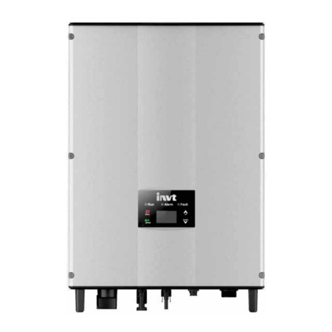
(2) Lift the inverter to suspend it on the installation bracket through
M8 hex socket cap screws;
(3) Finally, fix the inverter with the bracket. For firm installation, the
operators cannot release the device until the inverter is installed on
the bracket firmly.
(4)Fasten the screws.
Figure 4 Installation of inverter
Electrical installation
Figure 5 Electrical wiring of the inverter
OR
Figure 6 Connection of the AC side and the inverter
Below are the electrical wiring steps of the three-phase inverter:
(1) Before connecting the three-phase AC grid cable to the inverter,
take lightning and short circuit protection measures in accordance
with the local electrical safety codes;
(2) As shown in Figure 6, connect and fastenL1、L2、L3、N (optional)
and PE conductors of the three-phase common grid to AC terminal,
and then connect the terminal to the AC port of the inverter;
(3) Fix and connect the DC output cables of PV board with the
matched DC connectors, and then connect the connectors to the DC
port of the inverter.
Operation
5.1 Inspection before operation
Check as follows before operation:
(1) Detect the voltage of the components is in the allowable input
voltage range of the inverter;
(2) Detect the voltage of the AC port at AC side is normal;
(3) Check the inverter is in good grounding;
(4) Ensure all switches are “off”;
(5) Ensure all electrical safety precautions are clearly-identified on
the installation site.
(6) Confirm the handheld keypad or communication module is in
correct connection.
5.2 Grid-tied operation
Please start the inverter as follows:
(1) Switch on the integrated DC switch;
(2) Use the handheld keypad or communication module to set the
time, date and area of the inverter;
(3) Switch on the breakers at the AC side;
(4) Observe the LED indicators and information displayed on the
LCD screen.
Green indicator blinks, others off: the inverter is power
on and in self-inspection;
Green indicator on, others off: the inverter is in power
generation after self-inspection----successful commissioning.
“Warn” or “Fault” indicators are on or blinking: the inverter is
power on, but fault occurs.
5.3 Accessories and wiring
The accessories are the handheld terminal, WiFi, ENET and GPRS.
Connect the 485 port of accessories to the RS485-M(4-10kW) or
RS485(12-40kW) port of the inverter; for the ACF inverter,
RS485-M(4-10kW) or RS485(12-40kW) is to the upper PC and
RS485-S(4-10kW) or EXT(12-40kW) is to the ammeter.
5.4 Regular maintenance
Stop the inverter as follows it needs maintenance, inspection and
troubleshooting:
(1) Switch off the breakers at the AC side;
(2) Switch off the integrated DC switch;
(3) Contact with customer service staff or local dealers.


