edesix VIDEOBADGE VB-400 User manual

VB-400 Series - Quickstart Guide - ED-006-021-08
Wearable Security for Professionals
1
ED-006-021-08
VIDEOBADGE VB-400
QUICKSTART GUIDE
Wearable Security for Professionals

VB-400 Series - Quickstart Guide - ED-006-021-08
2
Wearable Security for Professionals
CONTENTS
INTRODUCTION 3
CHARGING YOUR DEVICE 4
Solo Docking Station (VB-400-SOLO) 5
14 Port Docking Station (VB-400-DOCK14) 6
Battery Status LED 7
CONFIGURING YOUR DEVICE 8
IDENTIFYING AN RFID ASSIGNED BADGE 9
USING YOUR VIDEOBADGE VB-400 10
To Start / Stop recording (Congurable) 10
ACCESSORIES 13
REGULATORY INFORMATION 14

VB-400 Series - Quickstart Guide - ED-006-021-08
Wearable Security for Professionals
3
INTRODUCTION
Welcome, and thank you for choosing Edesix as your Body Worn Camera provider.
This simple guide will lead you through the set-up process of your VB-400 Body Worn Camera
and all accompanying accessories.
Lens
Buzzer
Speaker
Function
Button B
LED
LED
Function
Button C
Slider
Dual
Microphone
Front
Function Button
Function
Button A
LED
VB-400 Series - Quickstart Guide - ED-006-021-08
4
Wearable Security for Professionals
CHARGING YOUR DEVICE
Upon receiving your VB-400 VideoBadge, it is recommended that you fully charge the device before
usage.
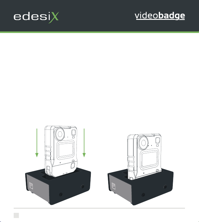
When charging using a Solo or 14 Slot docking station, insert the camera into the dock as shown in
the diagram.
Ensure the camera clicks securely in place. Check that the top LED blinks green to indicate charging
Slide down to
click into place
VB-400 Series - Quickstart Guide - ED-006-021-08
Wearable Security for Professionals
5
Once fully charged, the same LED will turn solid green. If the LED is not lit, the device is not charging.
Your VideoBadge will be fully charged within 8 hours from a at battery.
To enable charging you will require one of the following;
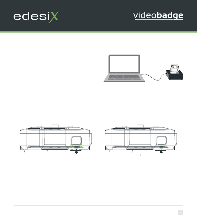
Solo Docking Station (VB-400-SOLO)
MConnected to your laptop
If you are charging your VB-400 camera via a Solo Docking Station (VB-400-SOLO) your VideoBadge
will bleep to indicate charging has commenced, and the LED, as indicated, will ash green to show
charging.
View on Top Face
Charging: Flashing green LED
View on Top Face
Fully Charged: Solid green LED

VB-400 Series - Quickstart Guide - ED-006-021-08
6
Wearable Security for Professionals
14 Port Docking Station (VB-400-DOCK14)
MConnected to a power supply and
Dock Controller
If you are charging your VB-400 camera via a 14
Port Docking Station (VB-400-DOCK14) the top
LED will ash green to show charging, and the
camera will bleep when successfully connected to
VideoManager.
View on Top Face
Charging: Flashing green LED
View on Top Face
Fully Charged: Solid green LED
Once fully charged, the same LED will turn solid green. If the LED is not lit, the device is not charging.
Your VideoBadge will be fully charged within 8 hours from a at battery.
VB-400 Series - Quickstart Guide - ED-006-021-08
Wearable Security for Professionals
7
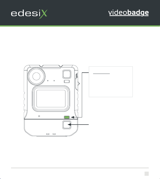
Battery Status LED
To quickly understand the current battery status of your VideoBadge, press the bottom button on
the front face of the camera and refer to the bottom right LED.
Colour Key:
Green LED: OK
Orange/Yellow LED: Low
Red LED: Critical
Battery Status Button
(Congurable)

VB-400 Series - Quickstart Guide - ED-006-021-08
8
Wearable Security for Professionals
CONFIGURING YOUR DEVICE
Prior to using your VB-400 VideoBadge, your
device must be congured and assigned to you
using VideoManager. For detailed information on
how to congure your device, please refer to the
VideoManager User Guide.
Each VideoBadge requires a valid VideoManager
Licence, or access to the Edesix Cloud Service, in
order for you to assign devices and access footage.
For further details, see the VideoManager User
Guide.
To ascertain whether your VideoBadge has been
congured, please view the top left LED on your
device.
This LED will turn solid green once congured and
assigned. Your VideoBadge is charged, assigned
and ready to use when the LEDs shown are both
solid green.
Congured, charged & assigned
Solid green light
Please Note: If you try to use your VideoBadge before it has been assigned, the bottom LED on the
front face of the camera will start to ash red and you will hear an alarm tone.
You will not be able to use your camera until it has been assigned.

VB-400 Series - Quickstart Guide - ED-006-021-08
Wearable Security for Professionals
9
IDENTIFYING AN RFID ASSIGNED BADGE
Once your device is congured, your system administrator may wish badge users to utilise an RFID
system for camera assignment. For further information on using RFID with your VB-400, please refer
to the VideoManager User Guide.
Having presented your RFID card, your docked, assigned VB-400 will identify itself with a solid red
LED as shown.
RFID Assigned Badge

VB-400 Series - Quickstart Guide - ED-006-021-08
10
Wearable Security for Professionals
USING YOUR VIDEOBADGE VB-400
The Edesix VB-400 series of cameras are intuitive and simple to use.
To Start / Stop recording (Congurable)
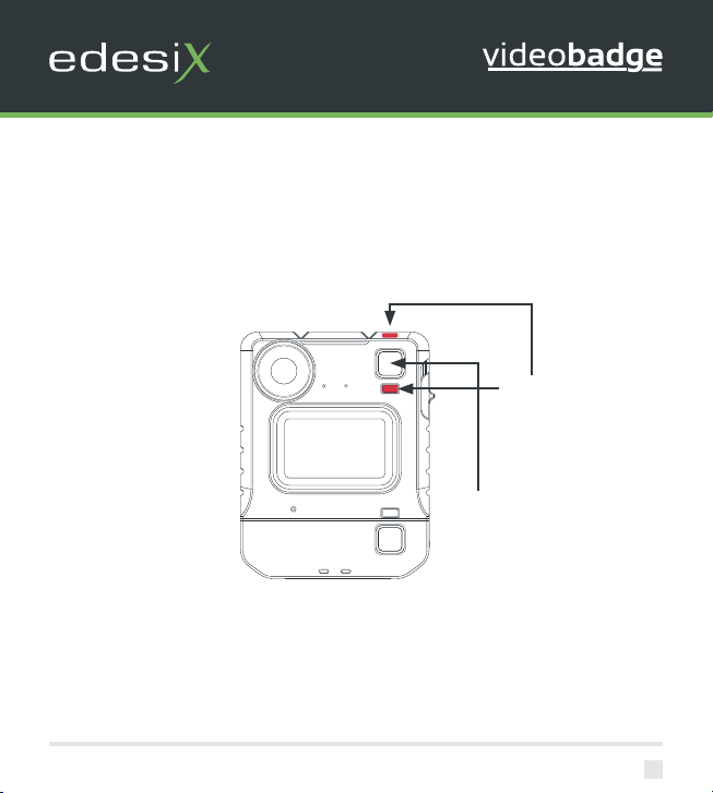
Users can activate recording by pressing on the single front button located in the centre of the
badge as shown. Recording is stopped by pressing and holding the front button.
Record activation and deactivation buttons are congurable by Administrators.
Start Recording initiated will be indicated by a short bleep, the top right LED showing red and the
top front LEDs showing red.
Solid red LED
Press centre button to
start/stop recording
VB-400 Series - Quickstart Guide - ED-006-021-08
Wearable Security for Professionals
11
Stop Recording initiated will be visual through the top right and front LEDs turning from red to o,
accompanied by a longer, high pitched bleep.
Please Note: All buttons are congurable. Please consult with your administrator if you have any
issues.
No LED
Power Down Button
(Congurable)

VB-400 Series - Quickstart Guide - ED-006-021-08
12
Wearable Security for Professionals
Please note: The Camera should always remain upright when capturing footage.
You should now be ready to use your VideoBadge! We hope that you enjoy using your new VB-400
Body Worn Camera.
For further set-up information, please refer to the VideoManager User Manuals.

VB-400 Series - Quickstart Guide - ED-006-021-08
Wearable Security for Professionals
13
ACCESSORIES
Designed for optimum performance and comfort in a wide range of situations, the VB-400 comes
with a variety of xing types to suit every uniform type and body shape.
For more information, please visit https://www.edesix.com/products/accessories
VB-400 Series - Quickstart Guide - ED-006-021-08
14
Wearable Security for Professionals
REGULATORY INFORMATION
Product Name Model
Edesix VideoBadge VB-400
Radio Equipment Directive
Hereby Edesix declares that the radio equipment type VB-400 is in compliance with Directive 2014/53/EU. The full text of the EU declaration of
conformity is available at the following internet address: https://www.edesix.com/videobadge-vb-400-declaration-of-conformity
The VB-400 can transmit in the following frequency bands:
• 2.412 GHz to 2.472 GHz with a transmit power of no more than 44mW
• 5.180 GHz to 5.320 GHz with a transmit power of no more than 18mW
RF Exposure Information (SAR)
The VB-400 contains a radio transmitter and receiver. It is designed and manufactured not to exceed the safe body worn human exposure limits for RF
energy set by the Council of the European Union for occupational exposure.
Edesix Ltd, 16 Forth Street, Edinburgh, EH1 3LH, UK
BATTERIES
• Do no discard your battery into a re.
• Do not disassemble, crush, puncture, shred, or otherwise attempt to change the form of your battery.
• Do not leave your battery in an extremely high temperature environment that can result in an explosion or the leakage of ammable
liquid or gas.
• Do not subject your battery to extremely low air pressure that may result in an explosion or the leakage of ammable liquid or gas.
• Do not dispose of batteries with household waste.

VB-400 Series - Quickstart Guide - ED-006-021-08
Wearable Security for Professionals
15
FCC STATEMENT
WARNING: Any changes or modications not expressly approved by the party responsible for compliance could void the user’s authority to operate
this equipment.
This equipment has been tested and found to comply with the limits for Class B digital devices, pursuant to part 15 of the FCC Rules. These limits are
designed to provide reasonable protection against harmful interference in a residential installation. This equipment generates and can radiate radio
frequency energy and, if not installed and used in accordance with the instructions, may cause harmful interference to radio communications.
However there is no guarantee that interference will not occur in a particular installation. If harmful interference is suspected, the user should
determine its cause by turning the equipment o and on. The user is encouraged to try to correct the interference by one or more of the following
measures:
• Reorient or relocate the receiving antenna.
• Increase the separation between the equipment and the receiver.
• Connect the equipment into an outlet on a circuit dierent from that to which the receiver is connected.
• Consult the supplier or an experienced radio/TV technician for help.
This device complies with part 15 of the FCC Rules. Operation is subject to the following two conditions: (1) This device may not cause harmful
interference, and (2) this device must accept any interference received, including interference that may cause undesired operation.
FCC RF EXPOSURE INFORMATION (SAR)
This device is designed and manufactured not to exceed the emission limits for exposure to radio frequency (RF) energy set by the Federal
Communications Commission of the U.S. Government.
The exposure standard for wireless devices employs a unit of measurement known as the Specic Absorption Rate, or SAR. The SAR limit set by the
FCC is 1.6 W/kg. Tests for SAR are conducted using standard operating positions accepted by the FCC with the device transmitting at its highest
certied power level in all tested frequency bands. Although the SAR is determined at the highest certied power level, the actual SAR level of the
device while operating can be well below the maximum value. This is because the device is designed to operate at multiple power levels so as to use
only the poser required to reach the network.
In general, the closer you are to a wireless base station antenna, the lower the power output. While there may be dierences between the SAR levels of
various devices and at various positions, they all meet the government requirement.

Table of contents
Other edesix Digital Camera manuals


