manuals.online logo
Brands
  1. Home
  2. •
  3. Brands
  4. •
  5. Edge-Core
  6. •
  7. Network Router
  8. •
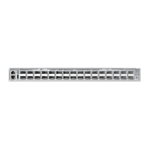
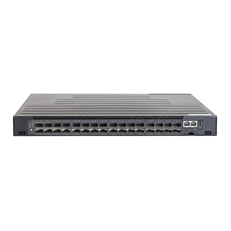
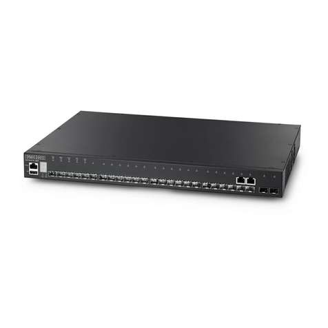
  9. Edge-Core AS7712-32X User manual

Edge-Core AS7712-32X User manual

Other manuals for AS7712-32X

1

Other Edge-Core Network Router manuals

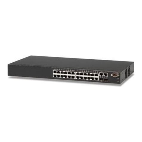
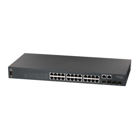
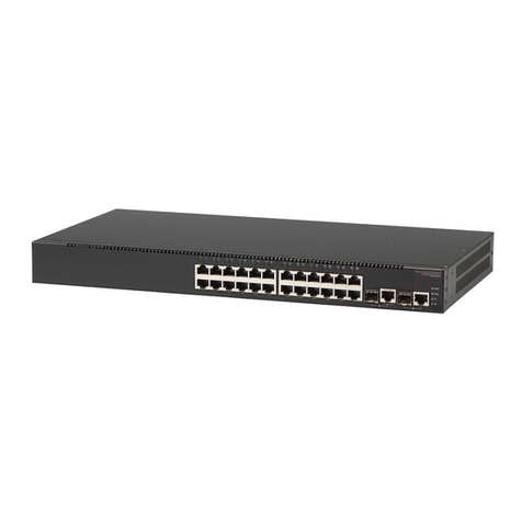
Edge-Core ECS4310-26T User manual

Edge-Core

Edge-Core ECS4310-26T User manual

Edge-Core ES3528MV2 Programming manual

Edge-Core

Edge-Core ES3528MV2 Programming manual

Edge-Core ES3510 Programming manual

Edge-Core

Edge-Core ES3510 Programming manual

Edge-Core ES4612 Programming manual

Edge-Core

Edge-Core ES4612 Programming manual

Edge-Core ES4625 Programming manual

Edge-Core

Edge-Core ES4625 Programming manual

Edge-Core ECS4210-12P Programming manual

Edge-Core

Edge-Core ECS4210-12P Programming manual

Edge-Core ECS4610-24F User manual

Edge-Core

Edge-Core ECS4610-24F User manual

Edge-Core ECS4610-24F User manual

Edge-Core

Edge-Core ECS4610-24F User manual

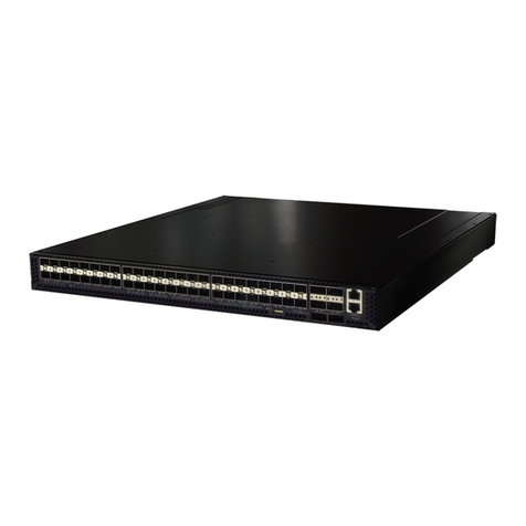
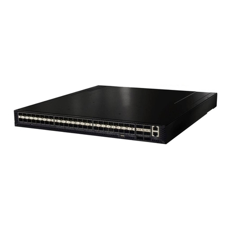
Edge-Core AS5710-54X User manual

Edge-Core

Edge-Core AS5710-54X User manual

Edge-Core ECS4510-28F User manual

Edge-Core

Edge-Core ECS4510-28F User manual

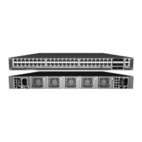
Edge-Core AS4630-54TE User manual

Edge-Core

Edge-Core AS4630-54TE User manual

Edge-Core AS5835-54T User manual

Edge-Core

Edge-Core AS5835-54T User manual

Edge-Core VR-100 User manual

Edge-Core

Edge-Core VR-100 User manual

Edge-Core ECS3510-26P Programming manual

Edge-Core

Edge-Core ECS3510-26P Programming manual

Edge-Core ES4624-SFP Programming manual

Edge-Core

Edge-Core ES4624-SFP Programming manual

Edge-Core ES3528M-PoE User manual

Edge-Core

Edge-Core ES3528M-PoE User manual

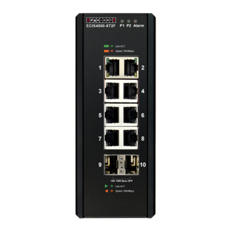
Edge-Core ECIS4500 Series User manual

Edge-Core

Edge-Core ECIS4500 Series User manual

Edge-Core ECS4620-28F User manual

Edge-Core

Edge-Core ECS4620-28F User manual

Edge-Core ECS3510-28T Programming manual

Edge-Core

Edge-Core ECS3510-28T Programming manual

Edge-Core DCS209 User manual

Edge-Core

Edge-Core DCS209 User manual

Edge-Core ECS2000-50T User manual

Edge-Core

Edge-Core ECS2000-50T User manual

Edge-Core AS7946-30XB User manual

Edge-Core

Edge-Core AS7946-30XB User manual

Edge-Core ES3510 User manual

Edge-Core

Edge-Core ES3510 User manual

Edge-Core AS5912-54X User manual

Edge-Core

Edge-Core AS5912-54X User manual

Popular Network Router manuals by other brands

TRENDnet TEW-435BRM - 54MBPS 802.11G Adsl Firewall M Quick installation guide

TRENDnet

TRENDnet TEW-435BRM - 54MBPS 802.11G Adsl Firewall M Quick installation guide

Siemens SIMOTICS CONNECT 400 manual

Siemens

Siemens SIMOTICS CONNECT 400 manual

Alfa Network ADS-R02 Specifications

Alfa Network

Alfa Network ADS-R02 Specifications

Barracuda Networks Link Balancer quick start guide

Barracuda Networks

Barracuda Networks Link Balancer quick start guide

ZyXEL Communications ES-2024PWR Support notes

ZyXEL Communications

ZyXEL Communications ES-2024PWR Support notes

HPE FlexNetwork 5510 HI Series Openflow configuration guide

HPE

HPE FlexNetwork 5510 HI Series Openflow configuration guide

Allied Telesis AT-AR236E quick start guide

Allied Telesis

Allied Telesis AT-AR236E quick start guide

ADTRAN NetVanta 3458-PoE quick start

ADTRAN

ADTRAN NetVanta 3458-PoE quick start

C&H Technologies EM405-8 manual

C&H Technologies

C&H Technologies EM405-8 manual

Huawei WiFi Mesh 3 Product description

Huawei

Huawei WiFi Mesh 3 Product description

Addonics Technologies ISC8P2G-S Quick install guide

Addonics Technologies

Addonics Technologies ISC8P2G-S Quick install guide

Atel W02 Arch+ Faqs

Atel

Atel W02 Arch+ Faqs

Allnet ALL0333AU user guide

Allnet

Allnet ALL0333AU user guide

Sercomm Genesis OC3505D Quick installation guide

Sercomm

Sercomm Genesis OC3505D Quick installation guide

Billion BIPAC 5102 Series user manual

Billion

Billion BIPAC 5102 Series user manual

TP-Link TD-8817 QIG

TP-Link

TP-Link TD-8817 QIG

Motorola MR1900 user guide

Motorola

Motorola MR1900 user guide

Cisco SOHO Series Regulatory compliance and safety information

Cisco

Cisco SOHO Series Regulatory compliance and safety information

manuals.online logo
manuals.online logoBrands
  • About & Mission
  • Contact us
  • Privacy Policy
  • Terms and Conditions

Copyright 2025 Manuals.Online. All Rights Reserved.

– 1 –
Quick Start Guide
1. Unpack the Switch and Check Contents
AS7712-32X
100G Data Center Switch
Rack Mounting Kit—2 front-post brackets, 2 rear-post
brackets, 20 screws, and 2 ear-locking screws
Power Cord—Japan, US, Continental Europe, or UK
Console Cable—RJ-45 to DB-9
Documentation—Quick Start Guide (this document)
and Safety and Regulatory Information
Note:
The switch has the Open Network Install
Environment (ONIE) software installer pre-loaded on the
switch, but no switch software image. Information about
compatible switch software can be found at
www.edge-core.com.
Caution:
The switch includes plug-in power supply (PSU)
and fan tray modules that are installed into its chassis. All
rear-installed modules must have a matching airflow
direction. That is, if the installed power modules have a
front-to-back (F2B) airflow direction, all the installed fan
tray modules must also have a F2B airflow direction.
The airflow direction of PSU and fan tray modules is
indicated by the color the release lever or handle on the
modules. Blue indicates an intake (cool) airflow, and red
indicates an exhaust (warm) airflow. Therefore, the fan tray
handles and PSU release levers must always be the same
color, either all blue or all red. The airflow direction of fan
tray modules is also indicated by labels on the modules.
2. Mount the Switch
Attach each of the front- and rear-post brackets to the
switch using four of the included bracket screws.
Use an additional two screws to secure each of the rear-post
brackets at the mid-point on the sides of the switch.
Use the screws and cage nuts supplied with the rack to
secure the switch in the rack.
3
1
1
4
2
1
2
3
Lock the position of the rear-post bracket ears using the
included position-locking screws.
You can also adjust the rear-post bracket ears to fit different
rack depths from 56 cm to 85 cm.
Caution:
Installing the switch in a rack requires two
people. One person should position the switch in the rack,
while the other secures it using the rack screws.
装置の吸排気に必要な領域をマニ ュ アル上に規定し て
いる。
3. Ground the Switch
Ensure the rack is properly grounded and in compliance
with ETSI ETS 300 253. Verify that there is a good electrical
connection to the grounding point on the rack (no paint or
isolating surface treatment).
Attach a lug (not provided) to an 18 AWG minimum
grounding wire (not provided), and connect it to the
grounding point on the switch rear panel. Then connect the
other end of the wire to rack ground.
Caution:
The earth connection must not be removed
unless all supply connections have been disconnected.
4. Connect Power
Install one or two AC power modules in the switch.
The switch supports up to two PSUs that must have the
same matching airflow direction as the installed fan tray.
Connect an external AC power source to the modules.
4
1
2
1
2
2
1
1
2
E102015-CS-R01
150200001281A
www.edge-core.com
32-Port 100G Ethernet Data Center Spine Switch
AS7712-32X
Quick Start Guide
– 2 –
5. Verify Switch Operation
Verify basic switch operation by checking the system LEDs.
When operating normally, the PS1/PS2, Diag, and Fan LEDs
should all be on green.
6. Perform Initial System Boot
If the network operating system (NOS) installer is located on
a network server, first connect the RJ-45 Management
(Mgmt) port to the network using 100-ohm Category 5, 5e
or better twisted-pair cable. (Not required if the NOS
installer is located on attached storage.)
Boot the switch. Wait for the ONIE software to locate and
execute the NOS installer, and then wait for the installer to
load the NOS software image.
Subsequent switch boots will bypass ONIE and directly run
the NOS software.
Note:
Refer to the network operating system (NOS)installer
and NOS documentation for details on software options and
set up for ONIE.
7. Connect Network Cables
For the RJ-45 Management port, connect 100-ohm Category
5, 5e or better twisted-pair cable.
Connect DAC cables directly to the QSFP28 slots. Or first
install QSFP28 transceivers in the slots and then connect
fiber optic cabling to the transceiver ports.
As connections are made, check the port status LEDs to be
sure the links are valid. Each QSFP28 port has four LEDs that
indicate valid links in the following modes:
◆1 LED Blue — 100 Gbps mode
◆1 LED Orange — 40 Gbps mode
◆1-4 LEDs White — 25 Gbps breakout mode (four lanes)
◆1-4 LEDs Green — 10 Gbps breakout mode (four lanes)
1
1
1
2
2
1
3
1
2
3
8. View the Product Label
The switch product label is located below the Console and
Management ports on the right side of the front panel. Pull
the label out to view the product information.
Hardware Specifications
Switch Chassis
Size (WxDxH) 438.4 x 515 x 43.5 mm (17.26 x 20.28 x 1.71 inch)
Weight 10.87 kg (23.96 lb), with two installed PSUs
Temperature Operating (F2B): 0° C to 45° C (32° F to 113° F)
Operating (B2F): 0° C to 40° C (32° F to 104° F)
Storage: -40° C to 70° C (-40° F to 158° F)
Humidity Operating: 5% to 95% (non-condensing)
Power
Consumption
550 Watts maximum
AC PSU
Power AC
Input Rating
100–240 VAC, 50-60 Hz, 650 Watts, hot pluggable
System AC
Input
100–240 VAC, 50-60 Hz, 6 A max.
Power DC
Output Rating
5 VDC @ 4 A
12 VDC @ 52 A
Regulatory Compliances
Emissions EN 55022:2010, Class A
EN 61000-3-2:2009, Class A
EN 61000-3-3:2008
FCC Class A
VCCI Class A
CE Mark
Immunity EN 55024:2010
IEC 61000-4-2/3/4/5/6/8/11
Safety UL (CSA 22.2 No 60950-1 & UL60950-1)
CB (IEC/EN60950-1)
1
1