Edge CS User manual

USER GUIDE
Color Touch Screen
Color Screen
User Guide

INTRODUCTION PARTS DESCRIPTION INSTALLATION OPERATING INSTRUCTIONS INTERNET UPDATES APPENDIX
TABLE OF CONTENTS
2
USER GUIDE
Table Of Contents
INTRODUCTION .............................................. 4
DISCLAIMER OF LIABILITY ............................................... 4
LIMITATION OF WARRANTY .............................................. 5
PARTS DESCRIPTION .................................. 10
PARTS INCLUDED ............................................................10
PARTS DESCRIPTION ..................................................... 11
INSTALLATION INSTRUCTIONS ......................................13
INSTALLATION ............................................. 14
Device Power Up .............................................................19
CTS/CS Device Descriptions .......................................... 20
CTS LAYOUT .................................................................. 21
CS LAYOUT.................................................................... 21
OPERATING INSTRUCTIONS .......................22
Navigating the Menu System ......................................... 22
Main Menu........................................................................ 22
View Camera..................................................................... 23
CS/CTS Alerts ................................................................ 24
Show Alerts ................................................................... 25
PROGRAMMING............................................................... 26
POWER LEVELS............................................................... 27
Custom Options ............................................................. 28
Diagnostics ..................................................................... 30
Trouble Codes ............................................................... 31
Manual DPF Regeneration ............................................... 33
Performance Tests ......................................................... 34
Injector Balance Rates .................................................. 36
Options............................................................................ 38
Alert Settings ............................................................... 38
Sound Duration ............................................................. 40
Screen Layout ............................................................... 40
Backlight Auto Dim......................................................... 41
Menu Time-out ................................................................ 42
Tire Size........................................................................ 42
Factory Reset................................................................ 44
Camera Delay ................................................................ 45
Help Menu ....................................................................... 46
Product Info ................................................................. 46
Vehicle Info .................................................................. 47
Contact Info ................................................................. 48

TABLE OF CONTENTS
INTRODUCTION PARTS DESCRIPTION INSTALLATION OPERATING INSTRUCTIONS INTERNET UPDATES APPENDIX
3
USER GUIDE
Tech Support Tools........................................................ 49
Fusion Update Software ................................................ 50
Possible Programming Errors ...................52
Update Required ............................................................ 52
Non-Stock condition ...................................................... 52
Accessories .................................................53
Edge Accessories System (EAS) ....................................... 53
OEM EGT Locations ........................................................ 54
APPENDIX.....................................................58
Edge Backup Camera....................................................... 58
Edge Mounting Solutions ............................................... 59
Trouble Shooting/Tips .................................................... 60
Commonly Used Acronyms .......................... 61
For additional questions not found in the user guide call:
Edge Products Technical Support
(888) 360-EDGE (3343)
8:00 am - 5:00 pm MST

USER GUIDE
INTRODUCTION PARTS DESCRIPTION INSTALLATION OPERATING INSTRUCTIONS INTERNET UPDATES APPENDIX
4
USER GUIDE
INTRODUCTION
DISCLAIMER OF LIABILITY
THIS IS A HIGH PERFORMANCE PRODUCT. USE AT YOUR OWN
RISK.
Do not use this product until you have carefully read the following agreement.
This sets forth the terms and conditions for the use of this product. THE IN-
STALLATION OF THIS PRODUCT INDICATES THAT THE BUYER HAS
READ AND UNDERSTANDS THIS AGREEMENT AND ACCEPTS ITS
TERMS AND CONDITIONS.
DISCLAIMER OF LIABILITY
Edge Products, LLC, MSDP Inc., and their successors, distributors, jobbers,
and dealers (hereafter SELLER) shall in no way be responsible for damage
resulting from incorrect use of this product. The BUYER/USER assumes all
responsibility for any damage resulting from the use or misuse of this product.
THE BUYER HEREBY WAIVES ALL LIABILITY CLAIMS.
The BUYER acknowledges that he/she is not relying on the SELLER’s skill or
judgment to select or furnish goods suitable for any particular purpose and that
there are no liabilities which extend beyond the description on the face hereof
and the BUYER hereby waives all remedies or liabilities, expressed or implied,
arising by law or otherwise, (including without any obligations of the SELLER
with respect to tness, merchantability and consequential damages) or whether
or not occasioned by the SELLER’s negligence.
The SELLER disclaims any warranty and expressly disclaims any liability for
personal injury or damages. The BUYER acknowledges and agrees that the dis-
claimer of any liability for personal injury is a material term for this agreement
and the BUYER agrees to indemnify the SELLER and to hold the SELLER
harmless from any claim related to the item of the equipment purchased. Under
no circumstances will the SELLER be liable for any damages or expenses by
reason of use or sale of any such equipment.
The SELLER assumes no liability regarding the improper installation or misap-
plication of its products.
It is the installer’s responsibility to check for proper installation and if in doubt,
contact the manufacturer.

USER GUIDE
INTRODUCTION
INTRODUCTION PARTS DESCRIPTION INSTALLATION OPERATING INSTRUCTIONS INTERNET UPDATES APPENDIX
5
USER GUIDE
LIMITATION OF WARRANTY
LIMITATION OF WARRANTY
Edge Products, LLC, MSDP Inc., (hereafter “SELLER”) gives Limited War-
ranty as to description, quality, merchantability, tness for any product’s pur-
pose, productiveness, or any other matter of SELLER’s product sold herewith.
The SELLER shall be in no way responsible for the product’s open use and
service and the BUYER hereby waives all rights other than those expressly
written herein. This Warranty shall not be extended or varied except by a writ-
ten instrument signed by SELLER and BUYER.
The Warranty is Limited to one (1) year from the date of sale and limited solely
to the parts contained within the product’s kit. All products that are in ques-
tion of Warranty must be returned shipping prepaid to the SELLER and must
be accompanied by a dated proof of purchase receipt. All Warranty claims are
subject to approval by Edge Products Inc.
Under no circumstances shall the SELLER be liable for any labor charged or
travel time incurred in diagnosis for defects, removal, or reinstallation of this
product, or any other contingent expenses.
If the BUYER sends back a failed unit that is out of warranty and chooses to
buy a refurbished unit, the refurbished unit will only carry a 90 day warranty.
If the BUYER purchases a new unit at a predetermined discounted rate, it will
have the standard 1 year warranty.
Under no circumstances will the SELLER be liable for any damage or expenses
insured by reason of the use or sale of any such equipment.
IN THE EVENT THAT THE BUYER DOES NOT AGREE WITH THIS
AGREEMENT, THE BUYER MAY PROMPTLY RETURN THIS PROD-
UCT, IN A NEW AND UNUSED CONDITION, WITH A DATED PROOF OF
PURCHASE, TO THE PLACE OF PURCHASE WITHIN THIRTY (30) DAYS
FROM DATE OF PURCHASE FOR A FULL REFUND.
Note: This warranty is void for any new products purchased through auction
websites. Warranty is valid only for new products purchased through Autho-
rized Dealers (proof of purchase required for all warranty claims).

USER GUIDE
INTRODUCTION PARTS DESCRIPTION INSTALLATION OPERATING INSTRUCTIONS INTERNET UPDATES APPENDIX
INTRODUCTION
6
USER GUIDE
IMPORTANT INFORMATION ABOUT YOUR
VEHICLE’S WARRANTY — PLEASE READ!
Many of our customers ask, “Will your product void my vehicle’s manufac-
turer’s warranty?” While the answer is straightforward from a legal standpoint,
it’s important to educate our customers (and all aftermarket consumers) on
some industry realities and offer some common sense precautions to minimize
your risk. Edge is committed to providing quality products that are safe to use.
Our products do not cause damage to a vehicle when used as intended. Please
keep in mind that towing in anything higher than the towing level and hard
driving in race or extreme performance levels is not recommended.
Consumers of aftermarket products are protected by the Federal Magnusson-
Moss Warranty Act. The Act states that if something breaks on your vehicle and
you take it in for warranty repair, the dealer must honor your warranty unless
whatever modications you have added to your vehicle actually caused the
problem in question.
However, the reality is that many dealerships have been known to void warran-
ties on vehicles that use aftermarket products as a matter of policy. This applies
in particular to those aftermarket products that produce horsepower, such as
performance enhancement “chips,” modied intake manifolds, or aftermarket
exhaust systems, regardless of product brand.
You have strong legal protection as a consumer in regard to your vehicle’s
warranty. However, Edge strongly recommends you always disconnect and
remove your module/programmer and monitor when you take your vehicle to a
dealer for warranty work. In addition, leaving the product connected may affect
dealer diagnostic analysis and CAN tool functions. Edge makes every effort to
produce product that can be easily removed.
Note: Even if you disconnect your unit, your dealer may detect the use of any
programmer—even if the unit has been removed.
Thank you for purchasing the CS and CTS product or device. The CS and
CTS products have been developed and produced from the highest quality
materials available to ensure the best performance for years to come. If you
have any concerns or questions, please contact us.
PLEASE take the time to register your product on line at edgeproducts.
com. Follow the instructions at link: http://www.edgeproducts.com/prod-
uct_registration.php

USER GUIDE
INTRODUCTION
INTRODUCTION PARTS DESCRIPTION INSTALLATION OPERATING INSTRUCTIONS INTERNET UPDATES APPENDIX
7
USER GUIDE
Why register? Benets of product registration:
Your Safety - • registering your product allows us to know exactly which
product you have and provide important product updates to you that im-
prove the quality and/or safety of the product
Enhanced Features• - almost all Edge products are easily updated via the
internet. We are constantly adding new features and improvementes to our
product that we know you will want to enjoy
Conrmation of Ownership• - provides a record in case of product loss,
theft, or required warranty work. When you call us for support our team
will already have much of the information they need to help you
Improved Product Development• - helps us better understand you (our
customers) and design products that meet your needs
Special Offeres• - allows us to inform you about special offers on acces-
sories and/or new products that t your vehicle and enhance your driving
experience
Extended Warranty Plan Opportunity• - within the rst 90 days of
ownership, Edge offers the option to buy a 1-year warranty extension to all
customers who register their product!
CAUTION: RETURN YOUR VEHICLE TO STOCK BEFORE TAKING
IT TO A SERVICE CENTER
If you take your vehicle to a service center they may, by your request or other-
wise, update your vehicle’s calibrations. All Edge modules and programmers
are built to operate with OEM calibrations. If this happens and your vehicle
has not been returned to stock your device will no longer be capable of pro-
gramming your vehicle. Therefore it is important that you return your vehicle
to stock before taking it in for service. Edge updates its active products (i.e.
those currently being manufactured) to work effectively with updated OEM
calibrations. However, this process can takes some time as Edge is not always
made aware of calibration changes made by the OEM. In the case of discon-
tinued products, Edge cannot ensure that your unit will work effectively if you
take your vehicle to a dealership and you are given, by your request or other-
wise, a new calibration.

USER GUIDE
INTRODUCTION PARTS DESCRIPTION INSTALLATION OPERATING INSTRUCTIONS INTERNET UPDATES APPENDIX
INTRODUCTION
8
USER GUIDE
THE CS (COLOR SCREEN)
The CS – an acronym for Color
Screen – has a familiar feel of Edge’s
popular legacy Attitude and Evolu-
tion. This new full-color digital
display features a ruggedized case,
user-friendly buttons, an easy-to-
navigate menu, and a light sensitivity
sensor that automatically
adjusts the brightness for improved
night viewing.
THE CTS (COLOR TOUCH SCREEN)
The CTS – an acronym
for Color Touch Screen
– is the pinnacle of what
made Edge popular: Innova-
tion. The CTS model features
a full-color, button-free,
touch-screen digital display;
an easy-to-navigate menu; a
light sensitivity sensor that au-
tomatically adjusts the bright-
ness for improved viewing; and a
video-in jack that supports
most o-the-shelf backup
cameras or DVD players with an
RCA jack.
INTRODUCING THE CS AND CTS MODELS
From the pioneers in display-based technology and engine performance man-
agement, comes the CS (Color Screen) and CTS (Color Touch Screen) for popular
domestic late model trucks and SUVs. Edge has reinvented four of its most popular
lines – the Insight*, Mileage Max*, Evolution, and Juice/Attitude*– with an all-new
look and cool new features.
THE BREAKDOWN
Four product lines, two screen options. It’s just that simple. Edge has taken its
best-known products – the Insight, Mileage Max, Evolution, and Juice/Attitude –
and given them a fresh look, improved features and benets, and pricing that will
make the competition obsolete. Consumers can pick the product that suits their
needs and then choose the screen option that best ts them.
*Coming soon - Check
www.edgeproducts.com for information

USER GUIDE
INTRODUCTION
INTRODUCTION PARTS DESCRIPTION INSTALLATION OPERATING INSTRUCTIONS INTERNET UPDATES APPENDIX
9
USER GUIDE
MOUNTING OPTIONS & ACCESSORIES
Both CS and CTS devices come with a standard
windshield mount from Arkon Resources Inc.,
the leader in device-mounting solutions. The
CS and CTS devices have a standard two-tab
system built in so they can accept an array of
dierent Arkon mounts. Additionally, the CS
unit will t into any of Edge’s popular custom
dash pods or pillar mounts. The CS and CTS
will accept various sensors (e.g., EGT sensor,
wide band O2 sensor, etc.), so customers can
customize their devices with accessories
to t their needs.
*NOTE: The CTS can also be used
with Edge’s custom dash pods by
using an adapter kit.

INTRODUCTION PARTS DESCRIPTION INSTALLATION OPERATING INSTRUCTIONS INTERNET UPDATES APPENDIX
USER GUIDE
10
PARTS DESCRIPTION
PARTS INCLUDED
Supplied Items Suggested Tools
CS or CTS Device1.
Arkon Windshield Mount2.
OBDII Cable3.
Mini USB Cable4.
CD5. (contains manual/update software)
Alcohol Wipe6.
Zip Tie Packet7.
Flat head screwdriver•
Cutting Pliers•
1
2 3
4 5
6 7

PARTS DESCRIPTION
INTRODUCTION PARTS DESCRIPTION INSTALLATION OPERATING INSTRUCTIONS INTERNET UPDATES APPENDIX
11
USER GUIDE
The Parts Description section of this manual describes each of the parts
included in your CS/CTS kit both physically as well as functionally.
CTS Device
The CTS device provides you with an interface to change
the performance programming on your vehicle as well
as gives you a multi-color touch screen display which
allows you to monitor multiple vehicle parameters in real
time. It is equipped with a large touch screen, a USB port
(for PC communication and electronic updates), a 16-pin
connector (for main vehicle communication), a video-in
jack, and a six-pin accessories connector which allows
you to further extend the capabilities of the device (see
the accessories page in the back of the manual).
CS Device
The CS device provides you with an interface to change
the performance programming on your vehicle as well as
gives you a multi-color screen display which allows you
to monitor multiple vehicle parameters in real time. It is
equipped with a full color screen, a Menu button, Up and
Down Arrow button, an Enter button, USB port (for PC
communication and electronic updates), a 16-pin con-
nector (for main vehicle communication), and a six-pin
accessory connector.
CS/CTS Windshield Mount
The windshield mount supplied with your CS/CTS kit is
designed to give you exibility in mounting your device
anywhere you’d like on your windshield. It is equipped
with a locking suction cup, a vertically adjustable arm,
and a 180 pivot head which allows you to ne tune the
viewing angle to your preference.
CS/CTS OBDII Connector
The OBDII connector/cable has two plugs, a smaller male
16-pin plug that connects to the back of your device, and
a larger rectangle style 16-pin male connector which
connects to the OBDII port located under the driver’s side
dashboard. The purpose of this connector is to provide
a communication link between your vehicle and your
device as well as provide a power and ground source.
PARTS DESCRIPTION

INTRODUCTION PARTS DESCRIPTION INSTALLATION OPERATING INSTRUCTIONS INTERNET UPDATES APPENDIX
12
USER GUIDE
PARTS DESCRIPTION
Mini USB Cable
The USB cable is used to connect your
device to your PC in order to perform
rmware and calibration updates using
Edge Products Fusion software. It is rec-
ommended you plug both USB connec-
tors into the computer, and complete
the Fusion software installation before
connecting the device.
CS/CTS Compact Disc
The CS/CTS compact disc contains the
Fusion update software, and PDF les
for the Installation manual as well as
the quick install guide.
Alcohol Pad
The alcohol pad is supplied for cleaning
the windshield prior to mounting the
suction cup equipped Arkon mount.
Zip Ties
The zip tie packet contains zip ties to
help you secure the OBDII cable out of
the way under the dash.

INSTALLATION
INTRODUCTION PARTS DESCRIPTION INSTALLATION OPERATING INSTRUCTIONS INTERNET UPDATES APPENDIX
13
USER GUIDE
The OBDII port is located under
the dash below the steering
wheel. The OBDII
port is placed in
dierent locations
under the dash for
dierent applica-
tions; refer to the
OBDII port location
drawing (left) to
help you locate your
OBDII port.
*07 + Ford Superduty
OBDII ports are located on the
left side of the wheel instead of the
right
* 94-97 Ford Powerstrokes are lo-
cated on the passenger side below and
to the left of the glove box.
FORD
DODGE
GM-CHEV
OBDII LOCATIONS
The OBDII port is a 16-pin connector like the illustration be-
low.
OBDII PORT
Step 1: Locating the OBDII Port
INSTALLATION INSTRUCTIONS

INTRODUCTION PARTS DESCRIPTION INSTALLATION OPERATING INSTRUCTIONS INTERNET UPDATES APPENDIX
14
USER GUIDE
INSTALLATION
Once you’ve removed
the necessary panels,
connect the OBDII
cable to the OBDII
port, and route the
cable under the dash,
out the side panel, up be-
tween the door seal trim
and the edge of the dash.
Tuck the cable back as far
as you can as you route it
up to the dash.
Remove the panel on the
side of the dashboard to
provide access to route
the OBDII cable from the
OBDII port up to the top
of the dash.
*On some vehicles you may
also need to remove the panel
directly under the steering
wheel
*Note: Leave
6-10 inches of
cable exposed on top
of the dash so you have
room to position the
control unit.
Step 2: Connecting/Routing the OBDII Cable

INSTALLATION
INTRODUCTION PARTS DESCRIPTION INSTALLATION OPERATING INSTRUCTIONS INTERNET UPDATES APPENDIX
15
USER GUIDE
Step 3: Position the Control Unit
Position the device
and the mount on the
windshield in the desired
location.
Pay attention to
where the suction
cup will mount on the
windshield.
Once you’ve identied
the suction cup posi-
tion on the windshield,
use the supplied alco-
hol wipe to thoroughly
clean the area. After
you’ve wiped the area
clean, let it dry for 2-3
minutes.
*Select a location that will
not impair your ability to view
the road/traffic/pedestrians
while you drive.

INTRODUCTION PARTS DESCRIPTION INSTALLATION OPERATING INSTRUCTIONS INTERNET UPDATES APPENDIX
INSTALLATION
16
USER GUIDE
Step 4: Connect the Mount and OBDII Cable
Before you attach the suc-
tion cup portion of the
mount to the window
attach it to the device.
Insert the tabs on the
mount into the slots on
the back of the device and
slide up (CTS) or to the
side (CS) until it stops.
Next, insert the connector on
the end of the OBDII cable
into the 16-pin connector on
the back of the device (this is
easier if done prior to
mounting the device on the
window). The connector only
ts one way so be sure that the
locking tab is on the bottom.
*The mounting tabs are a tight
fit by design in order to main-
tain a solid connection.

INSTALLATION
INTRODUCTION PARTS DESCRIPTION INSTALLATION OPERATING INSTRUCTIONS INTERNET UPDATES APPENDIX
17
USER GUIDE
Step 5: Position and Lock the Unit on the
Windshield
Once the alcohol has dried you’re
ready to attach the mount to
the windshield.
You’ll notice that the
mount has a locking tab.
This tab creates the suction
that will lock the mount to
the windshield. Make sure
the lock is in the “Unlocked”
position. Position the mount
where you’ve cleaned the
windshield, press rmly,
and push the tab to the
“Locked” position.
UNLOCKED
Once you’ve locked the mount to the
windshield, use the adjustment knobs to
ne tune the viewing angle and height of
the CTS/CS device.
VERTICAL ADJ. KNOB
This knob will allow you
to adjust the viewing
angle and height of the
control unit up or down.
VARIABLE ANGLE ADJ KNOB
This knob will allow you to
adjust the viewing angle of the
control unit in both horizontal
and vertical fashions. Use it to
ne tune your viewing angle.
LOCKED

INTRODUCTION PARTS DESCRIPTION INSTALLATION OPERATING INSTRUCTIONS INTERNET UPDATES APPENDIX
INSTALLATION
18
USER GUIDE
*Note: Some states prohibit mounting de-
vices that may obstruct your view. Please
check local and state laws to ensure
compliance.
For alternate mounting options visit
www.edgeproducts.com or www.arkon.com
After you’ve locked the mount and the CS/CTS device is
in place on your windshield, sit back in your drivers seat
and make sure the viewing angle is as desired. Check
to make sure the device doesn’t create a blind spot that
may impair your view of the road/trac/pedestrians
from the drivers seat.
Step 6: Verify Position and Viewing Placement

INSTALLATION
INTRODUCTION PARTS DESCRIPTION INSTALLATION OPERATING INSTRUCTIONS INTERNET UPDATES APPENDIX
19
USER GUIDE
The CS/CTS device will not power up until the vehicle is started. If
you wish to power the device prior to starting the vehicle, turn the
key to the run position and press the menu button (CS) or touch the
screen (CTS).
Device Power Up
Step 7: Remove Cable Slack/Replace Panels
After positioning
the device and the
mount, remove any
slack in the OBDII
cable and coil it be-
hind the side panel
you removed earlier.
Use the supplied zip
ties to secure the
coiled cable from
moving, falling down
under the dash, or inter-
fering with pedal opera-
tion. Replace all panels
removed during installa-
tion.

INTRODUCTION PARTS DESCRIPTION INSTALLATION OPERATING INSTRUCTIONS INTERNET UPDATES APPENDIX
INSTALLATION
20
USER GUIDE
CTS/CS Device Descriptions
654
9
2
8
1
53
10
3
2
8
1
9
7
6
4
7
3
This manual suits for next models
1
Table of contents
Popular Touchscreen manuals by other brands

COMFILE
COMFILE CUTOUCH CT1820 user manual
Elo Touch Solutions
Elo Touch Solutions B-Series Quick installation guide

Elo TouchSystems
Elo TouchSystems 2420L Product dimensions

Audiovox
Audiovox LCM 972TS - manual

Topcon
Topcon OPUS A6 Generation 2 Eco Technical data sheet

Russound
Russound XTS5.5 installation manual
MicroTouch
MicroTouch IC-215P-AW4-W10 user manual

Kenwood
Kenwood LZ-760R instruction manual

Elo TouchSystems
Elo TouchSystems 2242L Specification sheet
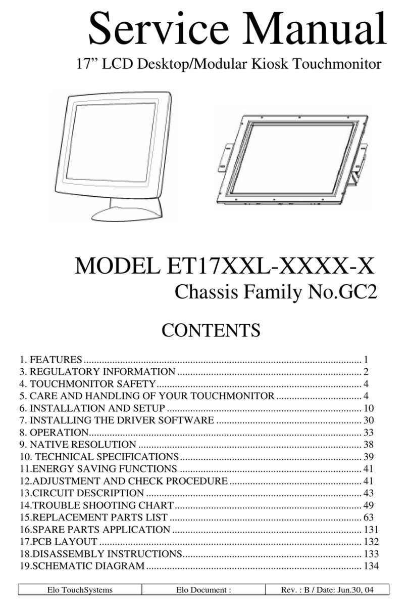
Elo TouchSystems
Elo TouchSystems ET17 XXL Series Service manual

Vantage Hearth
Vantage Hearth Equinox 73 EQ73TB-TI Installation
Elo TouchSystems
Elo TouchSystems 1517L user manual
