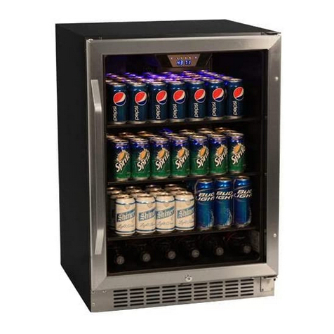
EdgeStar BR1500SSOD User manual

EdgeStar, 8606 Wall St, Suite 1800, Austin, TX 78754
support.edgestar.com • service@edgestar.com • edgestar.com
*Warranty service should be performed by an authorized service representative only.
Document Type: Service Manual
Version 1.112192017
SERVICE MANUAL
CAUTION: READ ALL SAFETY PRECAUTIONS IN THIS
MANUAL BEFORE SERVICING THE UNIT
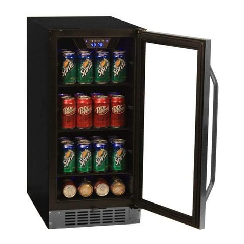
15" Built-In Kegerator
MODEL:
BR1500SS, BR1500SSOD, BR1500BL

CONTENTS
- 2 -
SAFETY PRECAUTIONS .............................................................................................................................................................2
PARTS IDENTIFICATION .............................................................................................................................................................3
DISASSEMBLY..........................................................................................................................................................................4-7
DOOR .....................................................................................................................................................................................4
LAMP………… ........................................................................................................................................................................4
DISPLAY BOARD& CONTROL BOARD & CONTROL BOARD...........................................................................................4-5
POWER BOARD & TRANSFORMER ..................................................................................................................................... 5
SENSOR & FAN......................................................................................................................................................................6-
COMPRESSOR PTC STARTER & OVERLOAD PROTECTOR..........................................…………………………….…….6-7
TROUBLESHOOTING...........................................................................................................................................................7-10
COMPRESSOR COMPONENTS ..........................................................................................................................................7
ANOTHER ELECTRIC COMPONENT ..................................................................................................................................8
SERVICE DIAGNOSIS CHART.............................................................................................................................................9
REFRIGERATING CYCLE ....................................................................................................................................................10
DESCRIPTION OF PCB ..........................................................................................................................................................11
SAFETY PRECAUTIONS

- 3 -
2. PARTS IDENTIFICATION
Model:BR1500SS,BR1500SS0D,BR1500BL
Front View

- 4 -
3. DISASSEMBLY
3-1 DOOR
(Models:BR1500SS,BR1500SS0D,BR1500BL )
Loosen 2 bolts fixing the lower door axis to the
lower hinge to remove the door. (Figure 1)
Lower Door
BOLT
Figure 1
3-2 LAMP
(Models:BR1500SS,BR1500SS0D,BR1500BL)
1. Loosen three screws. (figure 2)
screws
Figure 2
1. Unplug the led light connector. (figure 3)
Figure 3
2. Loosen four screws. (figure 4)
Figure 4
screw
3. Pull out the LED light. The LED light is like below.
(figure 5)
Figure 5
3-3 DISPLAY BOARD & CONTROL BOARD
(Models:BR1500SS,BR1500SS0D,BR1500BL)
1. Loosen three screws. (figure 6 )
2. Pull out the electrical box.
Figure 6
Screw
3. Unplug cable connectors. (figure 7)
.
Figure 7
4. Take off the control panel film.(figure 8)
Figure 8
connector

- 5 -
3. DISASSEMBLY
5. Pull out the display board assembly (figure 9)
Figure 9
6. Disassemble the display board。 (figure 10)
Figure 10
7. The control board is like below. (figure 11)
Figure 11
3-4 POWER BOARD & TRANSFORMER
(Models:BR1500SS,BR1500SS0D,BR1500BL)
1. Loosen four screws, Take off the compressor cover。
(figure 12)
Figure 12
screw
2. Loosen three screws. (figure 13)
Figure 13
3. The power board & transformer are like below. (figure 14)
Figure 14

- 6 -
3. DISASSEMBLY
3-5 SENSOR & FAN
(Models:BR1500SS,BR1500SS0D,BR1500BL)
1. Loosen two screws. (figure 1 5 )
screw
Figure 15
2. Loosen six screws. Pull out the rear air duct cover.
(figure 1 6 )
fan
screw
sensor
Figure 16
3. Loosen 1 screw. You can replace the sensor & fan.(figure
17)
wire housing
screw
evaporator
defrost
sensor
Figure 17
3-6 COMPRESSOR PTC STARTER & OVERLOAD
PROTECTOR
(Models:BR1500SS,BR1500SS0D,BR1500BL)
1. Open the box near compressor, The starter and overload
protector inside it.。 (figure 18)
Figure 18
2. Dismantle the compressor PTC starter and overload
protector. (figure 19)
Figure 19

- 7 -
3. DISASSEMBLY
1
3. The compressor PTC starter and overload protector is like
below. (figure 20)
Figure 20
4-1 COMPRESSOR COMPONENTS
Check the
resistance of
Motor
Compressor.
2 Check the
resistance of
PTC-Starter.
Check the resistance
among M-C, S-C and
M-S in Motor
Compressor.
Is it normal?
Check the resistance
of two terminals in
PTC-Starter.
Is it normal?
YES
NO Replace Compressor.
YES
NO
2
2 3
3
Replace
PTC-Starter.
3 Check OLP.
Check if applying
a regular OLP.
NO
Replace OLP.

- 8 -
4. TROUBLESHOOTING
Check if current flows to the
following components.
Cause.
a. Starting devices Shorted or broken.
b. OLP Poor contacting
or shorted.
c. Compressor coil Coil shorted.
d. Circuit Parts Poor contacting
or shorted.
4-2 ANOTHER ELECTRIC COMPONENTS
▼ Cooling is impossible
Compressor
doesn't run.
Replace
each component.
Running state of
Compressor is poor.
Check a starting
voltage. Low voltage. Raise the voltage.
Check if current flows
to starting devices.
Poor contacting
and broken.
Replace
each component.
Check current flowing
in coil of
Compressor.
Shorted.
Check capacity of OLP. Lack of capacity.
The items described
above are normal.
Coil of motor
Compressor.
Replace
the compressor.
▼ Cooling ability is poor
Fan motor
doesn't run.
Check Control PCB
Check current flowing
in the Fan Motor.
Poor contacting.
Coil is shorted.
Replace
each component.
Much frost are sticked
to the EVAPORATOR.
Check current flowing
of the following
components.
• Def. Sensor
Shorted. Replace
each component.

- 9 -
4. TROUBLESHOOTING
4-3 SERVICE DIAGNOSIS CHART
Problem
Possible Cause
Appliance does not operate. Not plugged in.
The appliance is turned off.
The circuit breaker tripped or a blown fuse.
Appliance is not cold enough. Check the temperature control setting. External
environment may require a higher
setting.
The door is opened too often.
The door is not closed completely.
The door gasket does not seal properly.
Turns on and off frequently. The room temperature is hotter than normal.
A large amount of contents has been added to the appliance.
The door is opened too often.
The door is not closed completely.
The temperature control is not set correctly.
The door gasket does not seal properly.
The light does not work. Not plugged in.
The circuit breaker tripped or a blown fuse. The bulb has
burned out.
The light button is “OFF”. Energy conservation button is on.
Vibrations. Check to assure that the unit is properly leveled.
The appliance seems to make too much noise. The rattling noise may come from the flow of the refrigerant,
which is normal.
As each cycle ends, you may hear gurgling
sounds caused by the flow of refrigerant in your refrigeration
appliance.
Contraction and expansion of the inside walls may cause
popping and crackling noises.
The appliance is not level.
The door will not close properly. The appliance is not level.
The door was reversed and not properly installed. The gasket is
dirty.
The shelves are out of position.
Display error code “E1”
The air sensor has an open circuit. Connection to main control
PCB is white color wires. Check the circuit, if it is normal,
the sensor may need to be replaced.
Display error code “E2”
The air sensor has a short circuit failure. Connection main
control PCB is white color wires. Check the circuit, if it is normal,
the sensor may need to be replaced.
Display error code “E3”.
The defrost sensor has an open circuit. Connection to main
control PCB is red color wires. Check the circuit, if it is
normal, the sensor may need to be replaced.
Display error code “E4”.
The defrost sensor has a short circuit failure. Connection to
main control PCB is red color wires. Check the circuit, if it is
normal, the sensor may need to be replaced.

- 10 -
4. TROUBLESHOOTING
4-4 REFRIGERATING CYCLE
▼ Troubleshooting Chart
LEAKAGE
PAR TIAL
LEAKAGE
Low owing sound of
Refrigerant is heard and
frost forms
A little high -
more than
ambient room
temperature.
WHOLE
LEAKAGE
Flowing sound of Refrigerant
is not heard and frost isn't
formed.
CLOG IN CAPILLARY
Flowing sound of Refrigerant
is heard and frost forms
A little high -
more than
ambient room
temperature.
A little high -
more than
ambient room
temperature.
A little high -
more than
ambient room
temperature.
Flowing sound of Refrigerant
is not heard and frost isn't
formed.
YES
No frost or forms
in inlet only
Faulty
Normal amount
Inject Refrigerant to
Observe the discharging
amount of Refrigerant.
No or not much
NO
YES
Compressor. Compressor and check
cooling operation.
Check Compressor Clogged or restricted
Normal formed
frost in Evaporator
Find and Repair Leak
Appliance does
not get cold
enough
Appliance does
not get cold at all
Does compressor
turn on?
Is gas leak detected?
Observe refrigerant disharging point. Oil dishcharge/stain is often best indicator. indicator. Use bubbles to locate hole in line,
evaporator or condensor.
No cooling
Is oil leak detected?
• No discharging of refrigerant
• The capillary tube is faulty.
• The lter dryer is faulty.
• The condensor is faulty.
• The evaporator is faulty.
• No discharging of refrigerant
• A little refrigerant discharges
• Normal cooling is possible when
charging refrigerant of regular amount
stated on specication plate / rating
label.
• A little refrigerant discharges
• Normal cooling is possible when
charging refrigerant of regular amount
stated on specication plate / rating
label.
Does frost form on
the evaporator?
Appliance does
not get cold
enough
PARTIAL
RESTRICTION
CAUSE STATE OF UNIT STATE OF EVAPORATOR TEMPERATURE
OF COMPRESSOR
COMMENTS
WHOLE
RESTRICTION
Appliance does
not get cold
NO

- 11 -
5.
DESCRIPTION
OF PCB
(Models:BR1500SS,BR1500SS0D,BR1500BL)

EdgeStar, 8606 Wall St, Suite 1800, Austin, TX 78754
support.edgestar.com • service@edgestar.com • edgestar.com
*Warranty service should be performed by an authorized service representative only.
DATE REVISION NOTES:
11/14/2017 Initial Document
12/19/2017 Formatting edits
This manual suits for next models
2
Table of contents
Other EdgeStar Freezer manuals

EdgeStar
EdgeStar BWC70SS User manual

EdgeStar
EdgeStar FP430 User manual

EdgeStar
EdgeStar CBR901SG User manual

EdgeStar
EdgeStar BBR900BL User manual

EdgeStar
EdgeStar FP430 User manual

EdgeStar
EdgeStar CBR1501SG User manual

EdgeStar
EdgeStar BWC120SS User manual

EdgeStar
EdgeStar CMF151L-1 User manual

EdgeStar
EdgeStar FP430 User manual

EdgeStar
EdgeStar VBR Series User manual