EdgeStar VBR Series User manual

EdgeStar, 8606 Wall St, Suite 1600, Austin, TX 78754
support.edgestar.com • [email protected] • edgestar.com
SERVICE MANUAL
EDGESTAR VBR SERIES BEVERAGE COOLER
Model:
VBR240
VBR440
VBR640
Document Type: Service Manual
Version: V1.1 06042019

CONTENTS
CONTENTS............................................................................................................................... 1
SAFETY PRECAUTIONS .......................................................................................................... 2
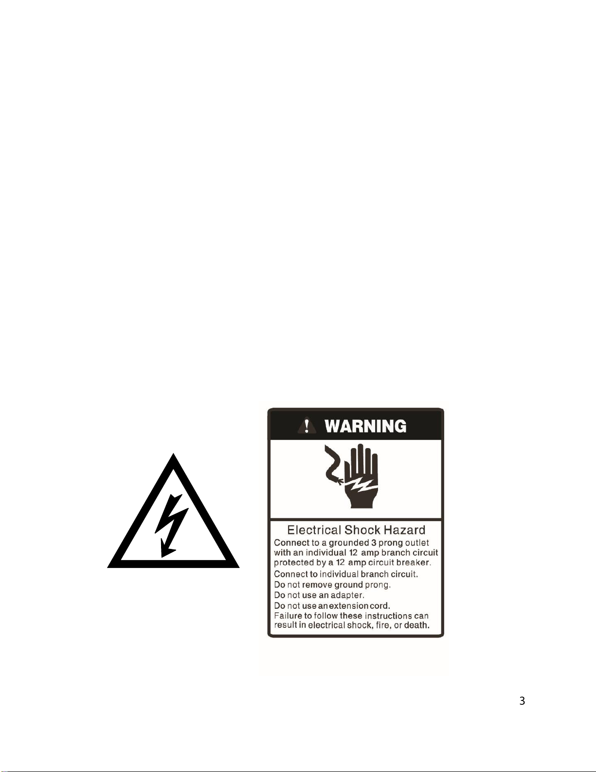
ELECTRICAL SAFETY.......................................................................................................... 3
GENERAL SAFETY............................................................................................................... 4
SPECIFICATIONS..................................................................................................................... 5
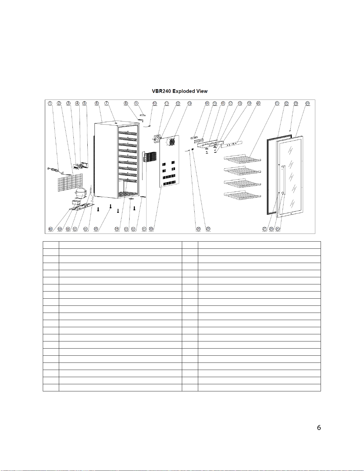
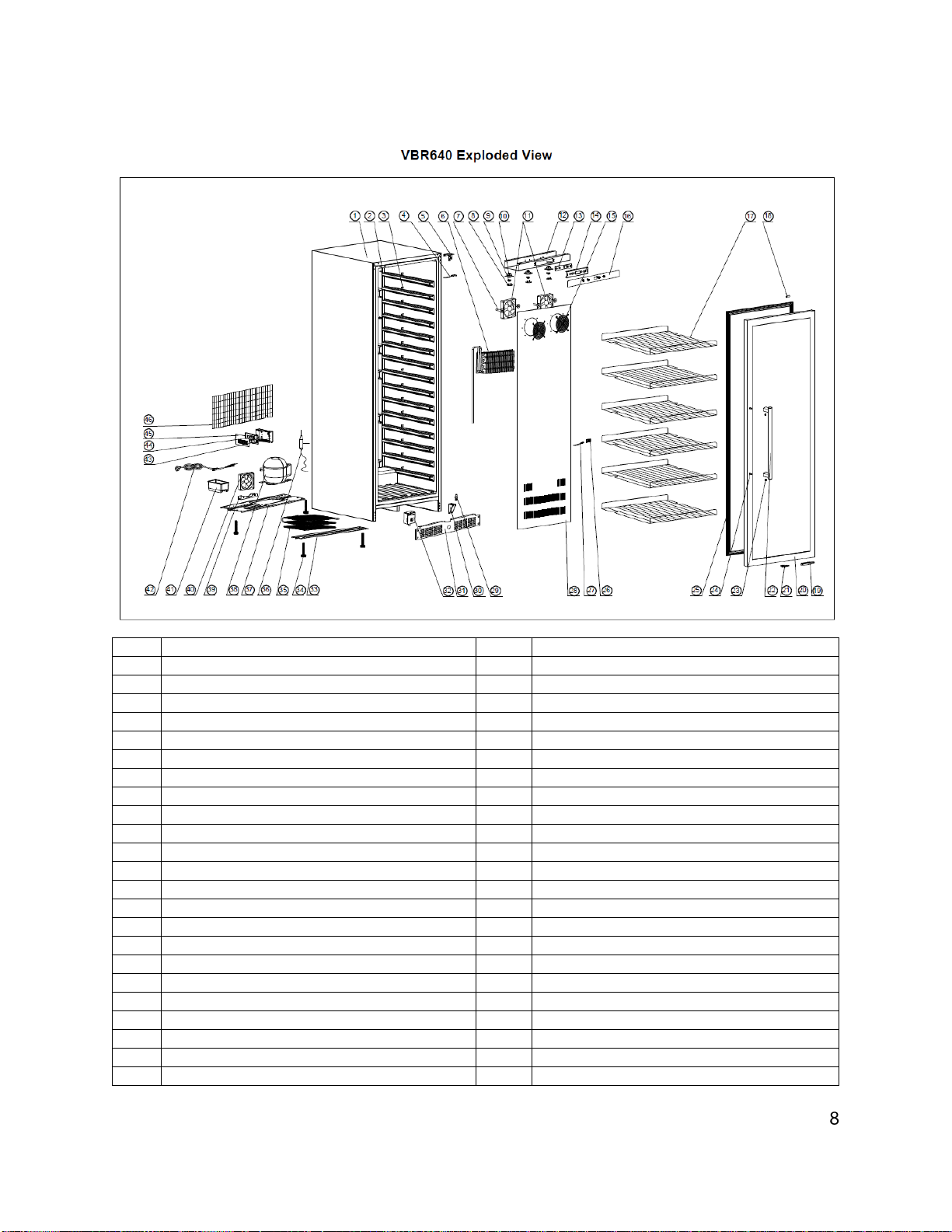
EXPLODED VIEW AND PARTS LIST........................................................................................ 6
SERVICE PRECAUTIONS FOR R600A SYSTEM..................................................................... 9
CONTROLS AND ELECTICAL SYSTEM................................................................................... 9
CONTROL FUNCTIONS........................................................................................................ 9
ALARM SYSTEM..................................................................................................................10
OTHER FUNCTIONS............................................................................................................11
TEST MODE.........................................................................................................................11
WIRING DIAGRAM AND SCHEMATIC.....................................................................................12
SENSOR RESISTANCE TABLE...............................................................................................13
PARTS REPLACEMENT PROCEDURES ................................................................................14
REPLACING THE VENTILATION GRILL / LOCK ASSEMBLY .............................................14
REPLACING THE LED LIGHT..............................................................................................15
REPLACING THE CONTROL PCB.......................................................................................16
REPLACING THE POWER PCB...........................................................................................16
REPLACING THE EVAPORATOR FAN MOTOR AND TEMPERATURE SENSOR..............17
REPLACING THE CONDENSER FAN MOTOR....................................................................18
LEVELING THE DOOR / HINGE ADJUSTMENTS................................................................18
REPLACING THE DOOR GASKET ......................................................................................19
REPLACING THE EVAPORATOR ASSEMBLY....................................................................20
REPLACING THE COMPRESSOR, COMPRESSOR PTC STARTER AND OVERLOAD
PROTECTOR .......................................................................................................................21
REPLACING THE FILTER DRIER........................................................................................21
REPLACING THE CONDENSER..........................................................................................22
TROUBLESHOOTING..............................................................................................................23

SAFETY PRECAUTIONS
WARNING: This manual and the information contained herein is intended for use
by certified technicians. The manufacturer or seller is not responsible for the
interpretation or misuse of the information provided, nor does it assume any
liability in connection with its use.
The safeguards and warnings indicated in this manual do not cover all possible
conditions which may occur. Common sense, caution, and care must be
exercised.
•To prevent electric shock, always unplug an appliance from the power supply before attempting
any service.
•Disconnect the power cord by grasping the plug, not the cord.
•Do not bypass, cut, or remove the grounding plug.
•Prevent water from spilling onto electric elements or the machine parts.
•Always refer to the rating label on the appliance for rated current and voltage.
•Always check line voltage and amperage.
•Always use exact replacement parts.
•Any attempt to repair a major appliance may result in personal injury and property damage.

Electrical Safety
•Do not exceed the power outlet ratings.
•It is recommended that the unit be connected to its own circuit.
•A standard electrical supply that is properly grounded in accordance with the National Electrical Code
and all state and local codes and ordinances is required.
•Do not use outlets that can be turned off by a switch or pull chain.
•Always turn the unit off and unplug it from the outlet when cleaning.
•Unplug the unit if it is not going to be used for an extended period of time.
•Do not operate the unit with a power plug missing the ground plug, a damaged cord, or a loose socket.
•Be sure the appliance is properly grounded.
•Do not bypass, cut, or remove the grounding plug.
•If the power cord is damaged, it must be replaced by the manufacturer or a qualified technician.
•Do not use extension cords or power strips with this unit. You may need to contact an electrician if it is
necessary to use a longer cord or if you do not have a properly grounded outlet. Do not modify the
power cord’s length or share the outlet with other appliances.
•Do not start or stop the unit by switching the electrical circuit’s power on and off.
•Immediately unplug the unit if it makes strange sounds, emits an odor or smoke and contact customer
service.
•Do not remove any part of the casing unless instructed by an authorized technician.
•Before the appliance is removed from service or discarded, remove any doors and cut off the power
cord.

General Safety
•Always unplug an appliance from the power supply before attempting any service. Disconnect the
power cord by grasping the plug, not the cord.
•Do not allow children or pets to play on or in the appliance.
•This machine is not intended for use by persons (including children) with reduced physical, sensory or
mental capabilities, or lack of experience and knowledge, unless they have been given supervision or
instruction concerning use of the machine by a person responsible for their safety.
•Do not install or store this appliance where it will be exposed to the weather.
•Disconnect from the power socket before cleaning or maintenance.
•If the plug (power cord) is damaged, it must be replaced by the manufacturer or an authorized service
representative.
•This machine shall be repaired only by an authorized service representative. Only genuine
replacement parts should be used.
•If connected to a circuit protected by fuses, use time-delay fuses with this appliance.
•Do not lean items against the glass door.
•Please do not close the door with excessive force. If it is found difficult to close the door, please check
for obstruction.
•When you plan to dispose of this unit in the future, please comply with the local waste disposal
regulations. Remove any doors so that children and pets will not be trapped in the unit.

Specifications
VBR240
Voltage / Frequency
AC 115V~60Hz
Amperage
1.1A
Input Power
120W
Color
White Cabinet; Stainless Steel Door
Refrigerant
R600a, 1.41 oz.
Temperature Range
36 - 43ºF
Dimensions (Height x Width x Depth )
49 1/4” x 21 1/2” x 24”
Weight
112 pounds
VBR440
VBR440
Voltage / Frequency
AC 115V~60Hz
Amperage
1.7A
Input Power
180W
Color
White Cabinet; Stainless Steel Door
Refrigerant
R600a, 1.66 oz.
Temperature Range
36 - 43ºF
Dimensions (Height x Width x Depth )
69 11/16” x 23 3/8” x 24 15/16”
Weight
151 pounds
Voltage / Frequency
AC 115V~60Hz
Amperage
1.7A
Input Power
180W
Color
White Cabinet; Stainless Steel Door
Refrigerant
R600a, 1.66 oz.
Temperature Range
36 - 43ºF
Dimensions (Height x Width x Depth )
58 1/8” x 23 1/2” x 24 1/4”
Weight
141 pounds

Exploded View and Parts List
**NOTE: Not all parts are stocked or considered serviceable / replaceable by manufacturer
VBR240
No
Part Name
No
Part Name
1
Power Supply Cord
21
Wire Shelf
2
Rear Grill
22
Door Gasket
3
Electrical Box Cover
23
Close Solenoid
4
Power PCB
24
Door
5
Electrical Box
25
Handle
6
Cabinet
26
Grub Screw
7
Decorative Plug
27
Pin
8
Top Hinge
28
Thermistor Supporter
9
Hinge Cover
29
Thermistor 2
10
Door Switch
30
Air Channel Cover
11
Fan Motor
31
Evaporator
12
Plastic Supporter
32
Bottom Hinge
13
Fan Guard
33
Lock Bracket
14
Control PCB
34
Plastic Post
15
PCB Supporter
35
Leveling Leg
16
Control Box
36
Condenser
17
Light Base
37
Filter Dryer
18
LED Light
38
Compressor
19
Light Cover
39
Drip Tray (Condensation Tray)
20
Control Panel Sticker
40
Compressor Base

VBR440
No
Part Name
No
Part Name
1
Cabinet
24
Door Gasket
2
Decorative Plug
25
Thermistor Supporter
3
Plastic Post
26
Thermistor 3
4
Top Hinge
27
Air Channel Cover
5
Evaporator
28
Door Axle
6
Plastic Supporter
29
Bottom Hinge
7
Light Cover
30
Kickplate
8
LED Light
31
Door Switch
9
Light Base
32
Door Lock Assembly
10
Fan Motor
33
Bottom Bracket
11
Control Box
34
Leveling Leg
12
Control PCB
35
Condenser
13
PCB Supporter
36
Filter Dryer
14
Fan Guard
37
Compressor Base
15
Control Panel Sticker
38
Compressor
16
Wire Shelf
39
Fan Supporter
17
Door Adapter (Door Axis)
40
Fan Motor
18
Pushing Bracket
41
Drip Tray (Condensation Tray)
19
Lock Bracket
42
Power Supply Cord
20
Door
43
Rear Grill
21
Handle
44
Electrical Box Cover
22
Grub Screw
45
Power PCB
23
Pin
46
Electrical Box

VBR440
No
Part Name
No
Part Name
1
Cabinet
24
Pin
2
Decorative Plug
25
Door Gasket
3
Plastic Post
26
Thermistor Supporter
4
Door Switch
27
Thermistor
5
Top Hinge
28
Air Channel Cover
6
Evaporator
29
Door Axle
7
Plastic Supporter
30
Bottom Hinge
8
Light Cover
31
Kickplate
9
LED Light
32
Door Lock Assembly
10
Light Base
33
Bottom Bracket
11
Fan Motor
34
Leveling Leg
12
Control Box
35
Condenser
13
Control PCB
36
Filter Dryer
14
PCB Supporter
37
Compressor Base
15
Fan Guard
38
Compressor
16
Control Panel Sticker
39
Fan Supporter
17
Wire Shelf
40
Fan Motor
18
Door Close Solenoid
41
Water Drip Tray (Condensation Tray)
19
Door Adapter (Door Axis)
42
Power Supply Cord
20
Door
43
Electrical Box
21
Lock Bracket
44
Power PCB
22
Handle
45
Electrical Box Cover
23
Grub Screw
46
Rear Grille

SERVICE PRECAUTIONS FOR R600A SYSTEM
Features of R600a refrigerant
•Achromatic and odorless gas.
•Flammable gas and the ignition (explosion) at 494°C / 921°F.
•Upper/lower explosion limit: 1.8%~8.4%/Vol.
Features of an R600a refrigeration unit
•Requires about 60% of the refrigerant required by an R134a system
•The suction pressure is below 1bar (abs) (14.5 PSI) during the operation.
•Any type of dryer is applicable
•The compressor has a label referring to the R600a refrigerant.
CONTROLS AND ELECTICAL SYSTEM
CONTROL FUNCTIONS
Silent Mode vs Dynamic Mode:
In the Dynamic Climate mode, the interior fan cycles on 20 seconds and off 30 seconds to
circulate the inside air evenly even when the set temperature is reached. Dynamic Climate
mode is NOT the factory preset mode. To change to Dynamic Climate mode, touch and hold the
DOWN key for approximately five seconds. The beverage fridge will beep five times to confirm
Dynamic Climate mode is on. To change back to default (Silent) mode (Also referred to as
energy saving mode), touch and hold the UP key for approximately five seconds. The beverage
fridge will beep three times to confirm default (Silent) mode is on.
Eco Demo Mode:
By pressing and holding the “UP” & “DOWN” and “LIGHT” keys all at the same time for at least
5 seconds, the indicator light will flash five times to confirm the unit has been put into Eco Demo
mode. The indicators for Fahrenheit and Celsius degree will be ON. In Eco Demo mode, the
compressor and all fan motors are OFF. NOTE: To perform the multi-key function, press and
hold the first key, then press the rest key the required number of times and then release all the
keys.
SABBATH Mode:
Sabbath mode is available for the observance of certain religious holidays. This mode turns off
the displays, interior light and audible alarms and prevents them from turning on again. Normal
cooling operations will still take place. To initiate Sabbath mode, press the POWER and LIGHT
keys at the same time for at least 5 seconds. The indicator light will flash four times and confirm
the Sabbath mode is ON. Sabbath mode can be exited by repeating the above process. The
Sabbath Mode will automatically exit after 96 hours.

ALARM SYSTEM
Temperature Display
During normal operation, the temperature display on the control panel will show the temperature
inside the appliance.
The temperature display will flash if:
•A different temperature is being set
•The temperature in deviates by more than 5°C from the set temperature. Note: To view the
“set” temperature at any time, touch the “UP” or “DOWN” mark, the “set” temperature will
temporarily flash in the LED display for 5 seconds.
If the LED readouts display the icon “--" and flash, that means the display temperature is out of
the range from -9 to 37ºC for Celsius degree and from 16 to 99ºF for Fahrenheit degree. That is
normal.
Temperature Alarm
An alarm will sound if the temperature rises or falls outside the temperature range. The
temperature display will flash at the same time. The temperature the appliance is set at
determines the temperature the appliance recognizes as being too warm or too cool.
The alarm will sound and the temperature display will flash if:
•When there has been a lengthy interruption to the power supply.
•When too many items have been put into the unit at one time.
•When the door is not been closed tightly.
Door Alarm
If the door has been left open for more than 60 seconds, the alarm will sound. After closing the
door, once the set temperature has been reached in the appliance, the alarm stops and the
temperature display stops flashing. However, if the noise disturbs you, you can switch the alarm
off before this if you wish by pressing the POWER key once. The alarm will stop. The
temperature display will continue to flash until the set temperature has been reached. The
display will then light up constantly, and the alarm system is fully active again.

OTHER FUNCTIONS
Temperature Memory Function
In the event of a power interruption (power surge, breaker switch, etc.), the unit will remember
the previous temperature settings. When the power is recovered, the unit will operate with the
last temperature set-point.
Interior Light
Touching the LIGHT button toggles between 2 modes of operation for the internal lights:
Functional (default) mode and showcase mode. If you are in functional (default) mode, the lights
will turn on only when the door is open. If you are in showcase mode, the lights will be on all the
time.
Defrosting
•Defrosting is performed each time the total running time for the compressor reaches
•10 hours.
•During the defrosting cycle, the compressor is OFF and the fans operate continuously.
•After 30 minutes, the defrosting cycle is completed
•During the defrosting cycle, the storage temperature may vary by 5 or 6 degrees.
•Frost may be accumulate on the evaporator if the unit is repeatedly opened in a high heat or
high humidity locations. If this frost pattern does not clear within 24 hours, your unit will
require manual defrosting.
ºF/ºC Selector
Select the temperature display setting in Fahrenheit or Celsius degree. To change the
temperature from Fahrenheit to Celsius or from Celsius to Fahrenheit, press and hold the
LIGHT key for 5 seconds.
TEST MODE
Press and hold the “LIGHT” and “UP” keys at the same time for 5 seconds with the power
ON. The indicator light will flash twice to confirm the input and the unit will run in the TEST
MODE. The compressor and all fan motors will operate continuously & independent from the
SET temperature. At the same time, the display shows the icon “--". The TEST Mode will
automatically exit after 30 minutes or you can stop the TEST mode by disconnecting the unit
from power source.

Wiring Diagram and Schematic

SENSOR RESISTANCE TABLE
No.
Measured Temperature (C °)
RESISTANCE OF SENSOR (kΩ)
1
-30
116.55
2
-28
104.97
3
-26
94.67
4
-24
85.49
5
-22
77.30
6
--20
69.99
7
-18
63.44
8
-16
57.58
9
-14
53.32
10
-12
47.60
11
-10
43.35
12
-8
39.53
13
-6
36.08
14
-4
32.97
15
-2
30.16
16
0
27.62
17
2
25.32
18
4
23.24
19
6
21.35
20
8
19.63
21
10
18.07
22
12
16.65
23
14
15.35
24
16
14.17
25
18
13.10
26
20
12.11
27
22
11.21
28
24
10.39
29
25
10.00
30
26
9.63
31
28
8.94
32
30
8.30
33
32
7.72
34
34
7.18
35
36
6.69
36
38
6.23
37
40
5.81
38
42
5.42
39
44
5.06
40
46
4.73
41
48
4.43
42
50
4.15
•The tolerance of sensor resistance is ±5%
•Be sure to measure the sensor resistance after keeping the sensor more than 3 minutes
at a measuring temperature. (It needs delay due to sensor speed.)

Parts Replacement Procedures
Replacing the ventilation grill / lock assembly
1. With assistance, tilt the unit back and remove screws 1,2, & 4. Be careful to hold the glass
door firmly after removing the screws. Pull down to remove the glass door and place it on a
padded surface to prevent scratching it.
2. Remove the two screws (3) that secure the ventilation grille to the reinforced bracket. At the
same time remove the four bolts (2 and 4) that fix the reinforced bracket to the cabinet.

3. Remove the four screws (2 and 3) that secure the bottom of the grill to the cabinet bottom
4. Reverse the steps used to remove the ventilation grill when reinstalling the new grill.
Replacing the LED Light
1. Remove enough shelves to allow you proper workspace
2. Remove the LED light cover with a small screwdriver
3. Pull down to remove the LED light PCB and replace it with a new one
IMPORTANT: Insert the new LED light PCB with correct polarity

REPLACING THE CONTROL PCB
1. Remove enough shelves to allow you proper workspace
2. Unscrew the four screws (6) that secure the PCB box (4) to the top of cabinet
3. Pull down to remove the PCB box carefully.
4. Disconnect the cable from the control PCB (2)
5. Dismantle the PCB supporter (3) from the PCB box
6. Carefully remove the control PCB from the PCB supporter.
7. Replace the control PCB.
8. Installation is the reverse of removal
REPLACING THE POWER PCB
1. Remove the five screws (1) that attach the rear grille to the cabinet.
2. Remove the screws 3 and 6.
3. Pull out the electrical box base (4) & electrical box cover (7) and Power PCB (5).
4. Disconnect the cables from the Power PCB and then you can replace the Power PCB.
5. Installation is reverse of removal

REPLACING THE EVAPORATOR FAN MOTOR AND TEMPERATURE
SENSOR
1. Remove all shelves.
2. Remove the screws (2) that secure the air channel cover (1) to the cabinet.
3. Disconnect the evaporator fan motor wires. Then pull out the air channel cover.
4. Unscrew the thermistor supporter (4)
5. You can now replace the temperature sensor (3)
6. You can see the evaporator (8) which can be replaced
7. To replace the fan, remove the screws (5) that secure the fan motor F1C (7) to the air
channel cover and then you can replace the evaporator fan motor.

REPLACING THE CONDENSER FAN MOTOR
1. Remove the decorative grill
2. Disconnect the condenser fan motor lead from the cable or power PCB inside the electrical
box.
3. Remove the two screws (1) that mount the fan motor F0 (4) to the compressor base (2)
4. Take out the condenser fan motor and replace it. Make sure to refit the rubber washer (3) in
the original position and replace it if it shows signs of aging.
LEVELING THE DOOR / HINGE ADJUSTMENTS
1. With assistance, tilt the unit back and loosen the screws (1)
2. Adjust the glass door to make the door top is parallel with the cabinet top then tighten the
screws.
3. Hinge adjustments are necessary when:
a. The door gasket is not sealed sufficiently along the hinge side of the door.
b. The door gasket is compressed more than 1/16" (1.5mm) on the hinge side (causing
a poor seal elsewhere around the top.)
c. The distance between the door and cabinet is greater at the top than at the bottom,
or vice versa.

Replacing the Door Gasket
1. Open the door and detach the old door gasket (2) from the door frame (1).
2. Attach the new door gasket on the door frame being careful not to damage the door and
gasket.
This manual suits for next models
3
Table of contents
Other EdgeStar Freezer manuals

EdgeStar
EdgeStar BWC70SS User manual

EdgeStar
EdgeStar CMF151L-1 User manual

EdgeStar
EdgeStar CBR1501SG User manual

EdgeStar
EdgeStar CWR461DZ User manual

EdgeStar
EdgeStar BR1500SSOD User manual

EdgeStar
EdgeStar CBR901SG User manual

EdgeStar
EdgeStar CMF151L-1 User manual

EdgeStar
EdgeStar BBR900BL User manual

EdgeStar
EdgeStar BWC120SS User manual

EdgeStar
EdgeStar FP430 User manual