EDILGRAPPA 230DE T10 Operation instructions

2
CONCRETE CRUSHER 230DE T10
USE AND MAINTENANCE
INSTRUCTIONS
MANUAL

2

3
HYDRAULIC TOOLS
ITEM
P/N
CONCRETE CRUSHER 230DE T10
1.50.2237
NOTE FOR THE USER:
THE USE OF THIS MACHINE IS ALLOWED PROVIDED IT IS CONNECTED TO A
HYDRAULIC POWER UNIT COMPLIANT WITH THE 2006/42/EC DIRECTIVE AND
WITH LEGISLATION IN FORCE AND IS SUITABLE FOR THE TECHNICAL FEATURES
OF THE MACHINE TO BE INSTALLED

4
INDEX
0 SAFETY AND DANGER STICKERS - CE PLATE.................................................................5
0.01 LIST OF ACCESSORIES SUPPLIED WITH THE TOOL................................6
1 TECHNICAL FEATURES.................................................................................................7
1.01DESCRIPTION ......................................................................................................7
1.02 TECHNICAL FEATURES....................................................................................7
2 DELIVERY AND HANDLING ..........................................................................................8
2.01 HANDLING, TRANSPORT AND LIFTING ........................................................9
3 COMMISSIONING .......................................................................................................9
3.01 PRELIMINARY CHECKS ....................................................................................9
3.02 HYDRAULIC CONNECTION............................................................................10
4 USE ...........................................................................................................................13
6.01 OPERATIVE DEMOLITION STAGE................................................................13
5 ROUTINE MAINTENANCE..........................................................................................15
5.01 CLEANING THE MACHINE ..............................................................................16
5.02 CHECKING THE SCREWS...............................................................................16
5.03 GREASING..........................................................................................................16
6 PROBLEMS AND REMEDIES........................................................................................17
7 STORAGE AND RE-COMMISSIONING .........................................................................18
7.01 STORAGE ...........................................................................................................18
7.02 RE-COMMISSIONING.......................................................................................18
8 MACHINE DISPOSAL ..................................................................................................18
9 SPARE PARTS AND ACCESSORIES CATALOGUE...........................................................19
9.01 ORDER INSTRUCTIONS..................................................................................19

5
0 SAFETY AND DANGER STICKERS - CE PLATE
CAUTION!! FIRST READ PART 1 OF THE MANUAL REGARDING THE GENERAL
AND SAFETY REGULATIONS!
Position of plate and safety and danger stickers on the machine:

6
0.01 LIST OF ACCESSORIES SUPPLIED WITH THE TOOL
Protective cover, if appropriate
Manual: Safety and use and maintenance instructions
Declaration of conformity
Warranty certificate
Simple repair keys, if appropriate
Observe the warnings on the plates and stickers. Failure to do so could lead
to injury or death. Make sure the plates and stickers are attached and
legible. If not, apply them or request the maker for replacements.

7
1 TECHNICAL FEATURES
1.01DESCRIPTION
The machine mainly consists of a stem actuator (piston) activated by pressurised oil
delivered by a hydraulic power unit. Figure 1 shows the main parts of the equipment, in
particular:
1. Cylinder;
2. Jaws;
3. Tips:
4. Handle;
5. Mechanically activated grip;
6. Twin hose with quick couplings;
7. Guard.
Fig. 1
1.02 TECHNICAL FEATURES
Maximum output force from rod [ t ]
21.8
Maximum force at the tip [ t ]
10
Maximum operating pressure [ bar ]
700
Maximum input flow rate [ l/min ]
6
Dimensions: Length X Width X Height [ mm ]
( with fully open jaws )
801 X 510 X 212
Maximum opening of the jaws [ mm ]
230
Mass [ kg ]
23.4
8
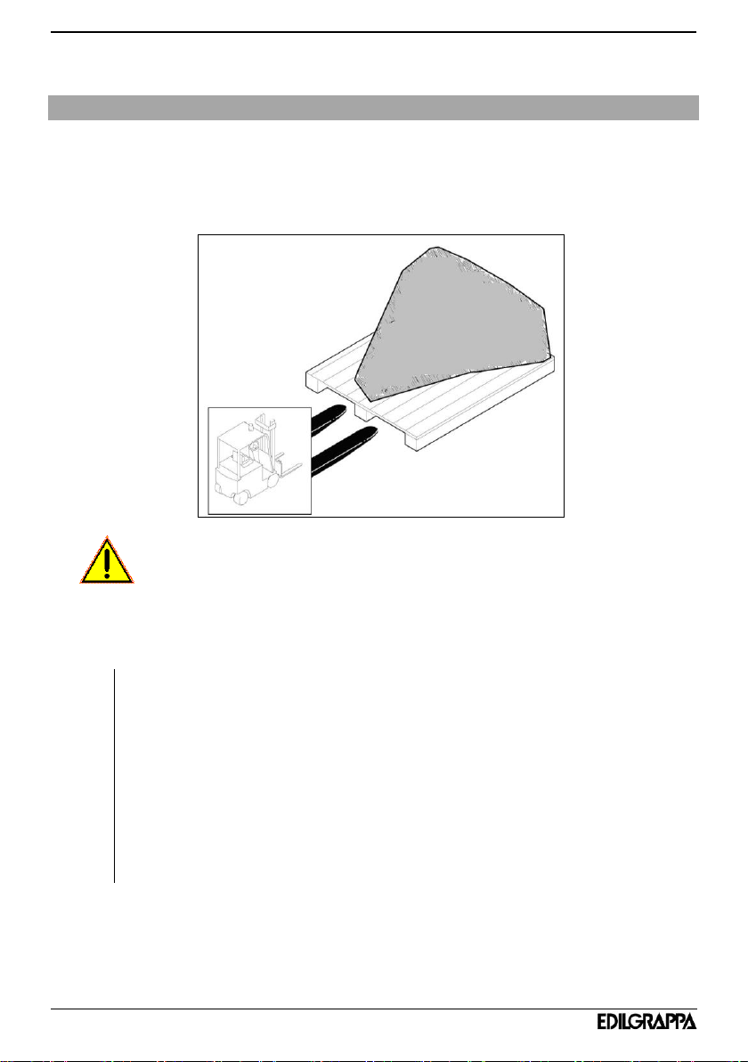
2 DELIVERY AND HANDLING
The crusher is usually shipped and delivered securely fixed onto a pallet, in a stable
position and appropriately wrapped in cellophane. The type of packaging can vary
according to the chosen means of transport and the destination. All the ordered
material is inspected before delivery to the customer.
CAUTION:
The packaging unloading must be performed with extreme care by means of a lifting
tool of appropriate capacity (e.g., forklift truck or other suitable means).
Then, the assembly must be positioned on a stable, horizontal surface.
Upon receipt, check the machine for any damage (breakages or major
denting) caused during transport. If so, it is necessary to immediately inform
the shipping company and to write on the Delivery note the “Accepted subject
to checking" clause.
In the event of damage, send a written complaint to the forwarder within 8
days of receipt.
Promptly inform Edilgrappa s.r.l. if major damage, caused during transport, is
found upon receipt, or if any parts are missing.
It is also necessary to check the delivered materials against the detailed
shipping list.

9
2.01 HANDLING, TRANSPORT AND LIFTING
The machine handling can be easily performed by gripping the machine itself by its
special grip and handle.
Handlingfor long distances:
Fix the crusher onto a pallet and handle it with the aid of a forklift truck or a pallet
truck in order to load it onto the means of transport (truck, train, etc...).
Loads must be moved in compliance with current occupational
safety regulations
After each use, place the machine on a stable surface checking that it has the
appropriate capacity.
3 COMMISSIONING
CAUTION:
The installer is responsible for checking that the appropriate technical features of
the hydraulic power unit are met, according to the model of crusher applied (see
Par. 1.02).
The crusher can only be installed on a hydraulic power unit compliant with Directive
2006/42/EC.
3.01 PRELIMINARY CHECKS
Before connecting the crusher, perform the following checks on the hydraulic power
unit:
A. check the correct operation of the safety devices;
B. check the condition of the quick couplings and the other coupling
components both on the crusher and the hydraulic power unit.
10
3.02 HYDRAULIC CONNECTION
To connect the crusher to the hydraulic power unit insert the quick coupling hoses (see
below) into the special attachments on the power unit.
After connecting the hoses, activate the crusher 5-6 times and check for any oil leaks.
CAUTION
Residual risk of burns: hydraulic oil, hoses and fittings can reach very high
temperatures with or without the cylinder applied. Use suitable personal protective
equipment.
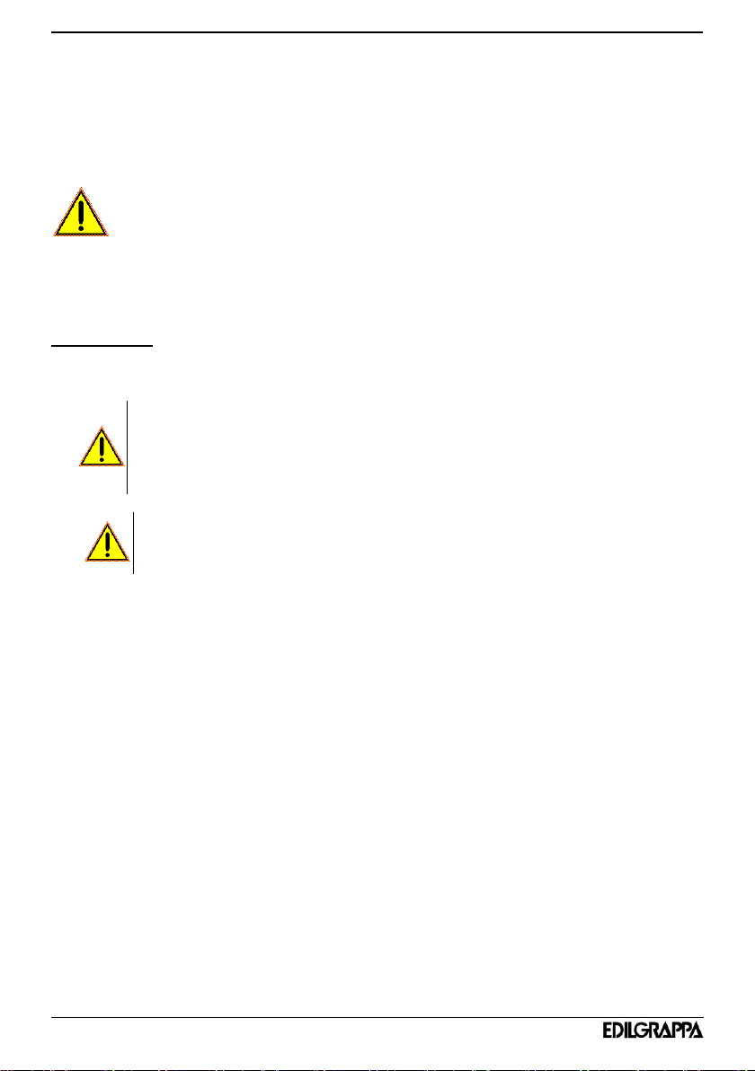
CONNECTION:
For connecting quick couplings, proceed as follows (for references see fig. 2):
Never use damaged quick couplings.
Never connect a quick coupling to the hydraulic power unit if the
hydraulic circuit is pressurised.
Make sure there is no residual pressure in the hydraulic circuit; otherwise, discharge
the pressure according to the instructions of the power unit manufacturer contained in
the relevant Use and maintenance manual.
Remove the anti-dust plugs from the couplings. The anti-dust plug can be easily
removed (see ref. 2 in fig. 2 );
Check for dust and any damage on the quick couplings and clean them if necessary;
Push the quick couplings against each other (see ref. 3 in fig. 2). The external ring nut
of the female coupling will automatically move in the opposite direction to that shown by
the arrows on the ring nut itself and will be locked in the correct position.
Check that the quick couplings cannot be easily separated and check that the external
ring nut of the female coupling is in the correct position.
Thoroughly clean all the quick couplings both on the cylinder and the power
unit before connecting them.
If, for any reason, pressure remains in the power unit hoses it will not be
possible to insert the male quick coupling into the female quick coupling.
Follow the instructions of the power unit manufacturer to remove pressure
11
Fig. 2
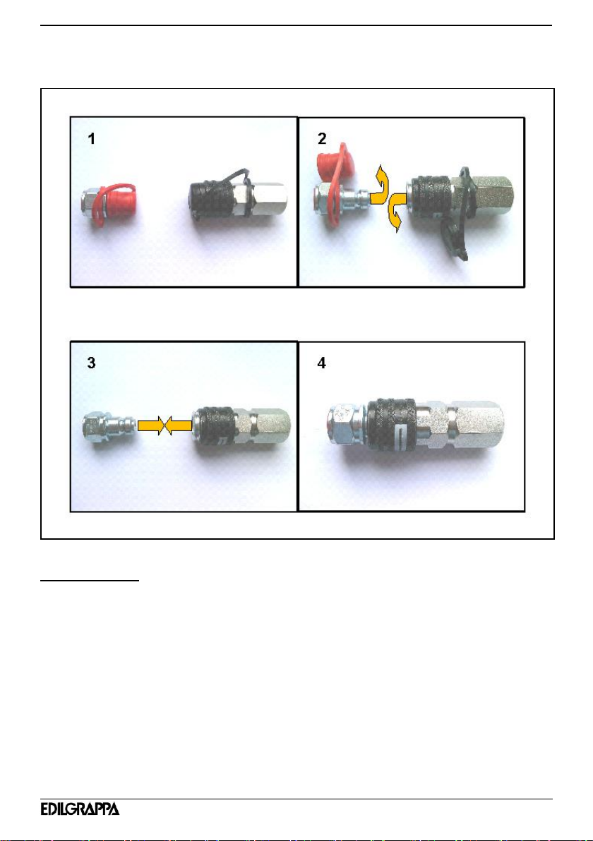
DISCONNECTION:
For disconnecting quick couplings, proceed as follows (for references see fig. 2A):
Make sure there is no residual pressure in the hydraulic circuit; otherwise,
discharge the pressure according to the instructions of the power unit
manufacturer contained in the relevant Use and maintenance manual.
Detach the quick couplings by rotating (A) the external ring nut of the female
coupling and making it slide (B) in the direction shown by the arrows; the male
coupling will come out of its position (see ref. 2 in fig. 2A).
Remove any dirt or oil residues from the quick couplings and the anti-dust plugs.
Replace the anti-dust plugs on the male and female quick couplings (see ref. 3 in
fig.2A).
12
Fig. 2A
CAUTION
After disconnecting the hoses, apply the anti-dust plugs to prevent impurities from entering
and protect the quick couplings.
13
4 USE
Controlled demolition crushers are designed to demolish concrete or brick walls depending
on the specific piece of equipment used for the dimensions indicated in the technical
characteristics, minimising noise, dust, vibrations and/or percussions.
The CRUSHER 230-DE T10 demolishes concrete walls (R=325 kg/cm²) with the maximum
dimensions indicated in the technical specifications.
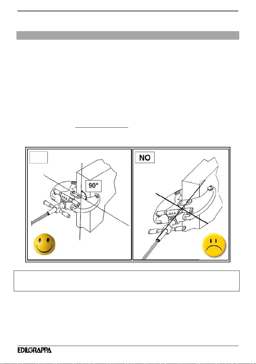
6.01 OPERATIVE DEMOLITION STAGE
Place the crusher jaws onto the object to be demolished so that it is perpendicular to the
axis of the object (fig. 3 shown as an example)
Fig. 3
If the crusher is in the wrong position, there can be damage to the tool due to the
significant thrust exerted by the cylinder.
-Place the jaws along the perpendicular line of the material to be demolished taking into
account the data shown in the technical features.
-After correctly positioning the jaws on the material to be demolished, move the
actuation handle in the direction of the "CLOSE” arrow until work is complete (see fig.
4).
YES

14
-Move it in the opposite direction “OPEN” to open the jaws and return to the original
position (see fig. 4).
-Make sure the actuation flange stops in the neutral position. This position can be
recognised by the alignment of the reference sign on the actuation flange with the
reference sign on the handle (see ref. 1 in fig. 4 ).
The following picture is only an example.
Fig. 4
CAUTION: TO AVOID BREAKING THE JAWS AND PINS AND TO OPTIMISE THE
FORCE OF THE TOOL, IT IS IMPORTANT TO OBSERVE THE INSTRUCTIONS ON
HOW TO POSITION THE MACHINE ON THE MATERIAL:
PLACE THE EQUIPMENT ONTO THE MATERIAL SO THAT IT IS PERPENDICULAR
TO AXIS OF THE MATERIAL ITSELF (fig. 3).
It is expressly forbidden to use the tool for purposes other than that indicated above
The Manufacturer declines responsibility for damage caused to people, animals or
property if the above machine is used for purposes other than those it was designed
for.

15
5 ROUTINE MAINTENANCE
1. All maintenance, inspection and cleaning interventions on the machine
must be performed with the machine disconnected from the hydraulic
power unit and cold (see the person in charge in the maintenance
intervals table);
2. Maintenance operations must be performed in a suitable place
according to current safety regulations;
3. Before any maintenance intervention, thoroughly clean the machine
(see Paragraph 5.01);
4. Wear suitable personal protective equipment while performing
maintenance work.
AT THE END OF EACH MAINTENANCE INTERVENTION ON THE
MACHINE, CHECK THAT ALL GUARDS HAVE BEEN CORRECTLY
REPLACED AND REINSTALLED.
Periodic maintenance schedule
Frequency
Operation
Method
Person
EVERY 8
HOURS
CHECKING THE INTEGRITY OF
THE MACHINE
Visual
Operator
EVERY 8
HOURS
MACHINE CLEANING
Para 5.01
Operator
EVERY 8
HOURS
TIP WEAR CHECK
Visual
Operator
/
TIP REPLACEMENT
/
Authorised
personnel
EVERY 8
HOURS
CHECK THE TIGHTNESS OF
NUTS AND BOLTS
Para 5.02
Operator
EVERY 8
HOURS
PIN GREASING
Para 5.03
Operator
16
In case of doubts during the maintenance interventions, to order spare parts or for
complex maintenance work, contact your authorised retailer.
5.01 CLEANING THE MACHINE
The cleaning operations must be performed using a dry cloth or compressed air. For
plastic surfaces the use of a cloth slightly dampened with water is allowed.
5.02 CHECKING THE SCREWS
Periodically, or every day in the event of frequent or prolonged work, make sure that all the
screws are perfectly tight.
FAILURE TO TIGHTEN LOCKING SCREWS CAN CAUSE SERIOUS DAMAGE.
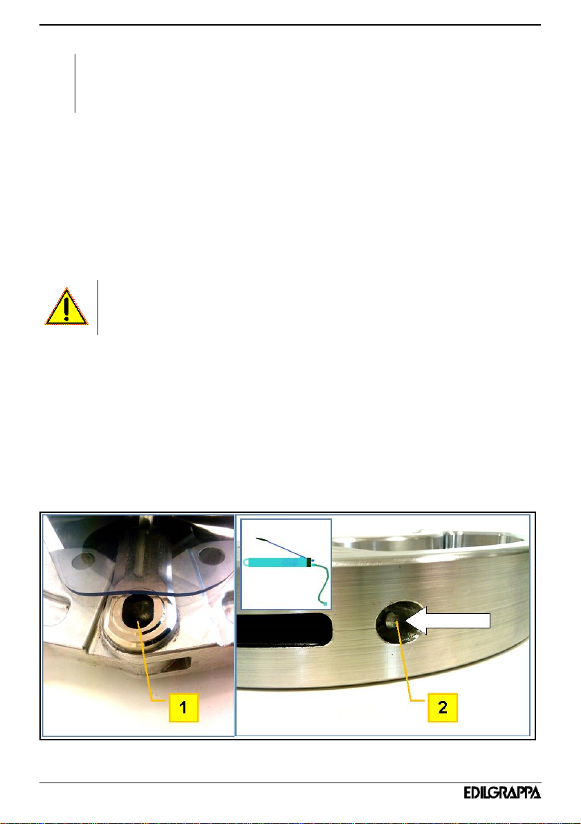
5.03 GREASING
Periodically or daily (in the event of frequent or extended works) check that the central pin (
see ref. 1 in fig. 5 ) is appropriately lubricated.
To grease the pin, use lithium-based water-repellent grease and apply it with a manual
grease gun (see example in fig. 5), pumping the grease into the grease nipple located on
one of the two jaws (see ref. 2 in fig. 5).
Fig. 5

17
6 PROBLEMS AND REMEDIES
The aim of this paragraph is to provide the user with the solutions to the problems (faults)
which occur most frequently. Do not perform any maintenance or repair interventions which
could compromise the safety of the machine.
The remedies marked by the letter Prequire the intervention of authorised personnel. Remedies
marked with the letter Mrequire the assistance of the maintenance man. Remedies marked with the
letter Ocan be performed by the operator.
FAULT
PROBABLE CAUSE
REMEDY
LOW
PERFORMANC
E CRUSHER
INSUFFICIENT FLOW
AND/OR HYDRAULIC
PRESSURE
MAKE SURE YOU HAVE
PERFORMED ALL CONNECTIONS
REQUIRED FOR OPERATION
CORRECTLY.
CONTACT THE CUSTOMER
SERVICE OF THE HYDRAULIC
POWER UNIT CONTROLLING THE
FLOW AND THE HYDRAULIC
PRESSURE.
P
VIBRATIONS
LOOSE OR MISSING
SCREWS OR BOLTS
CHECK THE TIGHTENING TORQUE
OF THE SCREWS OR BOLTS.
REPLACE THE MISSING SCREWS.
P
THE CRUSHER
DOES NOT
OPEN/CLOSE
LACK OF HYDRAULIC
FLOW AND/OR
PRESSURE
CHECK THE HYDRAULIC POWER
UNIT
P
ELECTRIC CABLE
(IF FITTED)
CHECK THE CORRECT
CONNECTION OF THE ELECTRIC
CABLE
O
EXTERNAL OIL
LEAKS
LOOSE FITTINGS
TIGHTEN LOOSE FITTINGS
O
DAMAGED HOSES
REPLACE HOSES
P
DAMAGED
COUPLINGS
REPLACE COUPLINGS
18
7 STORAGE AND RE-COMMISSIONING
7.01 STORAGE
In case of long periods of inactivity, proceed as follows:
- Store the equipment in a clean and dry place accessible only to authorised personnel.
- Thoroughly clean the tool;
- Lubricate it with a thin layer of oil.
7.02 RE-COMMISSIONING
Before re-commissioning the machine after a long period of inactivity, perform the following
checks:
- check and if necessary eliminate any oil leaks;
- grease all parts which can be lubricated;
- check the hoses are intact;
- check for any missing, worn or badly positioned parts;
- check nuts and bolts are tightened.
8 MACHINE DISPOSAL
When disposing of the machine, the various materials must be separated.
The tool comprises the following groups of materials:
- ferrous materials
- copper
- plastic
Observe current legislation when sorting, storing, recycling or disposing of these materials.
Only for EU countries:
This electric tool features the following recycling symbol. Consistently with Directive
2002/96/EC on waste electrical and electronic equipment (WEEE), at the end of its useful
lifetime, this product must be disposed of separately in suitable collection areas and not
together with normal domestic waste. A benefit for the environment and an advantage for
all.

19
9 SPARE PARTS AND ACCESSORIES CATALOGUE
9.01 ORDER INSTRUCTIONS
For technical assistance and spare parts also after the warranty period, inform the
manufacturer of the identification data shown on the nameplate and the serial number
printed on the crusher body.
Orders for spare parts must be accompanied by the following information:
1. Type of equipment
2. Serial number
3. Part number or position in exploded drawing
4. Quantity
5. Revision status of the manual indicated on the cover.
The Manufacturer can only supply the appropriate spare part if the required data is
complete, since subsequent improvements may have entailed structural variations to the
equipment and therefore to the spare parts.

20
Declaration of conformity
Maker: EDILGRAPPA srl
Machines and equipment for the building trade, industry
and rescue
Via Callesello, 4
31030 Borso Del Grappa (TV)
Name and address of person
authorised to draw up
the technical brief: Giacomo Rorato
Via Callesello, 4
31030 Borso Del Grappa (TV)
Generic name: Demolition crusher
Function: Demolition of concrete items with a maximum thickness of 230
mm
Type: Crusher
Model: 230DE T10
Commercial name: CONCRETE CRUSHER 230DE T10
Serial number: ________________
Year of construction: ________________
DECLARES THAT THE ABOVE-MENTIONED EQUIPMENT IS COMPLIANT WITH THE FOLLOWING
DIRECTIVES:
Machinery Directive 2006/42/EC (Proc. App. VIII)
Place: Borso Del Grappa TV
Date.................... Signature
PAOLO MAZZARO
(Legal representative)
Table of contents
Other EDILGRAPPA Power Tools manuals


