Edin Univox CLS-5 User manual

1
Univox®CLS-5
Environment-friendly loop amplifier for
TV rooms and installations in elevators/buses
Installation Guide
Univox CLS-5, art nr 212012

2
Content
Introduction .................................................. . . . . 3
Product overview.............................................. . . . . 4
Features and controls ................................................... 5
User information .............................................. . . . . 5
System check/Troubleshooting........................................... 5
Product maintenance and care ........................................... 6
Mounting and placement ....................................... . . . . 6
Installation setup ............................................. . . . . 6
Default settings ............................................... . . . . 6
Special settings for TV connection ............................... . . . . 7
Connecting an alert signal ...................................... . . . . 7
Loop installation guidance ...................................... . . . . 8
Technical description .......................................... . . . . 9
Power ................................................................. 9
Loop Output............................................................ 9
Inputs ................................................................. 9
Indication .............................................................. 9
Metal loss correction/treble control....................................... 9
Loop current ........................................................... 9
Indicators .............................................................. 9
Safety and Warranty ........................................... . . . 10
Troubleshooting............................................... . . . 10
Service ...................................................... . . . 10
Technical data ................................................ . . . 11
Environment and Recycling ..................................... . . . 11
Measuring devices............................................. . . . 11
Accessories .................................................. . . . 11

3
Introduction
Thank you for purchasing Univox® CLS-5 loop amplifier. We hope you will be satisfied with
the product! Please read this user guide carefully before installation and usage of the
product.
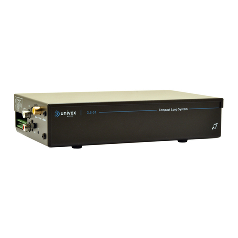
Univox CLS-5 is a modern loop amplifier designed for wireless listening through T-coil
equipped hearing devices. Wide range of operating voltages,110-240 VAC and 12-24 VDC,
supports its suitability for a number of applications, from on board vehicles to large TV
lounges and meeting rooms.
Digital and coaxial inputs, adjustment of time delay between the audio and video (TV
Sync), and built-in automatic SCART control are some of the features that enables easy
connection and operation with modern flat screen plasma- and LED/LCD TVs.
50% lighter, with 98% efficiency and 90% reduction of copper, compared to traditional
amplifiers, CLS-5 is one of the most environment-friendly loop drivers on the market.
CLS-5 features high-current output, essential for optimal signal broadcasting, and correctly
installed provides compliance with all the requirements of IEC 60118-4 and relevant
automotive standards.

4
Product overview
1. 6.
5.10.9.
Front panel
Rear panel
3.
4.
Side
7. 2.
8. 11.
12. 13.
Terminal block

5
Features and controls
1. On/Off. Yellow led indicates that the amplifier is connected to the mains power
2. In. Green led indicates that the amplifier is connected to the mains power and to a
signal source (TV, DVD, radio, etc.)
3. Loop. Blue led indicates that the current is delivered to the loop, i.e. the sound is
transmitting to hearing aids. The led is illuminated only when the signal is transmitted
from the source
4. Loop connection terminal. Connections to loop wire, terminal 1 and 2
5. TV Sync. Potentiometer for adjustment of time delay between the audio and video
signal
6. Loop current adjustment. Potentiometer for adjustment of loop current
7. In 3. RCA/Phono
8. Potentiometer for adjustment of microphone sensitivity
9. SCART connector for TV
10. SCART connector Ext, for VHS/DVD player etc
11. Microphone input
12. Digital input, optical
13. Digital input, coax
User information
CLS-5 should be installed and adjusted by a qualified technician. No maintenance is
normally required. In the event of technical problems, do not attempt to adjust the
amplifier yourself.
System check/Troubleshooting
1. Check that the amplifier is connected to the mains power (yellow LED illuminated).
Proceed to step 2.
2. Check the input connections. The cable between the amplifier and the signal source/s
(TV, DVD, radio etc.) must be properly connected, (green LED “In” illuminated). Proceed
to step 2.
3. Check the loop cable connection, (blue LED). The LED is illuminated only if the
amplifier is transmitting sound to the hearing aid and the system is working correctly.
If you are not receiving an audio signal in your hearing aid, verify that the hearing aid is
functioning properly and is set in T-position.

6
Product maintenance and care
Under normal circumstances the product does not need any special maintenance.
Should the unit become dirty, wipe it with a clean damp cloth. Do not use any solvents or
detergents.
Mounting and placement
CLS-5 can be wall-mounted (see template for wall mounting at the end of this Installation
Guide) or placed on a flat and stable surface. The wires between the loop figuration and the
driver should not exceed 10 meters and should be paired or twisted.
Important! The location must provide adequate unit ventilation.
The amplifier normally generates heat during operation and needs free space for plenty of
ventilation on all sides. To prevent fire, overheating or discoloration of the nearby objects,
the amplifier should not be placed close to fragile and easily flammable materials.
Installation setup
1. Connect the loop wire to the amplifier’s loop connection terminal marked Loop (4.).
2. Connect a suitable input signal source.
3. Connect the amplifier to mains or a 12-24 VDC power source. Yellow LED (1.)
illuminated.
Default settings
1. Check that there is an input signal, green LED In (2.) illuminated.
2. If microphone is connected to Mic input, adjust the microphone sensitivity (11.).
Adjust the microphone sensitivity (8.) so the green LED In (2.) is illuminated during the
program peaks.
3. Adjust the magnetic field strength by turning the loop current potentiometer Loop
(6.) until the program peaks reach 0dB, (400 mA/m). Verify the field strength with
Univox®FSM field strength meter enabling RMS measurement and 125 ms integration
time. Check the sound quality with the loop receiver, Univox®Listener. Some
installations require adjustment of treble level. The treble control is located inside the
CLS-5 (single control potentiometer inside the unit). When increasing the treble there
is an increased risk of self-oscillation and distortion.

7
Special settings for TV connection
• Digital In (12-13.)
Connect with optical or coax cable to TV models with digital output.
• RCA/phono (7.)
Connect the TV's audio output (AUDIO OUT or AUX OUT) to In 3 RCA/Phono (7.)
• SCART (9-10.)
Check that the TV´s SCART system works, i.e. the TV switches the mode automatically
when a connected externall unit (DVD etc.) is turned on. Disconnect the SCART cable
from the TV and connect it to the output Ext (10.) on the CLS-5 unit. Connect an
additional SCART cable between the SCART output on the TV and the SCART input (9.)
on the CLS-5.
• Sound adjustment/TV Sync (5.)
For adjustment of time delay between the audio and video signal use the TV sync
adjustment potentiometer.
Connecting an alert signal
The alert signal system can be triggered in three ways:
1. External Doorbell drive: +24 VDC Doorbell. Terminal 3-6 on the terminal block
2. External trigger: 5-24 V AC/DC. Terminal 4-5 on the terminal block
3. External switch: Terminal 3-4 and 5-7 are shorted separately. The external switch is
connected between 3-4 and 5-7.
The acoustic indication suppresses the sound in the loop and initiates a broadband
harmonic sound that covers most of the non-linear frequency hearing impairments.

8
Loop installation guidance
• The installation should initially be planned with a 2 x 1.5 mm² paired wire. Connect the
wires in series as a 2-turn loop. If the desired field strength is not achieved, connect
the wires in parallel creating a 1-turn loop. In installations where a standard round wire
is not suitable e.g. due to the limited space, a flat copper foil is recommended.
• Venues with reinforced structures can reduce the coverage area significantly.
• Analog signal cables should not be placed closely or in parallel to the loop wire.
• Avoid dynamic microphones to reduce the risk of magnetic feedback.
• The loop should not be installed closely to or directly on metal constructions or
reinforced structures. Otherwise, the field strength might be reduced substantially.
• If the shortest side of the loop area is longer than 10 meters, a figure eight loop
configuration should be applied.
• Verify that the overspill outside of the loop is acceptable. If not, a Univox® SLS system
should be installed.
• Relocate the electrical equipment that could create background magnetic field signals
or interference with the loop system.
• In order to avoid feedback from electronic instruments and dynamic microphones, do
not install wire near the stage area.
• A completely installed loop system should be tested with Univox® FSM field strength
meter and certified according to the IEC 60118-4 standard.
Univox Certificate of conformity, including a measurement procedure checklist, is
available at www.edin.se/support.

9
Technical description
Power
Built-in switched power supply 110-240 VAC
12-24 VDC as primary power supply or backup. Connection to 12 VDC will reduce the effect
Loop Output
Max current 10 Arms, short-circuit driven
Max voltage 24 Vpp (open output)
Frequency range 70-5000 Hz (±3dB)
Distortion <1% at 1 Ω DC and 80 μH
Connection Phoenix screw terminal
Inputs
Digital Optical/Coax
Mic 3.5 mm, 2-250 mV/5 kΩ (built-in phantom power)
TV/Ext SCART, 35 mV-10 V/ 5kΩ
In 1 screw terminal, 35 mV-10 V/5 kΩ
In 2 screw terminal, 25 mV-10 V/5 kΩ
In 3 RCA/phono, 35 mV/330 Ω
Indication
External door bell/telephone signal or trigger voltage can activate the built-in alerting
system with tone generator in the loop.
Metal loss correction/treble control
0 to +18 dB correction of high frequency attenuation - screw driver control.
Loop current
Loop current (6.) Screwdriver adjusted
Indicators
Power connection Yellow LED (1.)
Loop current Blue LED (3.)
Input signal Green LED (2.)

10
Safety and Warranty
The equipment should be installed by an audio visual technician observing 'good electrical
and audio practice' at all times and following the instructions within this document.
Connect the power to the amplifier before connecting to the network, otherwise
there is a risk of sparking.
The installer is responsible for installing the product in a way that may not cause risk
of fire, electrical malfunctions or danger for the user. Do not cover the loop driver. Only
operate the unit in a well ventilated, dry environment.
There are no user serviceable parts inside the unit. Refer servicing to qualified personnel.
Please observe that the product warranty does not include faults caused by tampering with
the product, carelessness, incorrect connection/mounting or maintenance.
Bo Edin AB shall not be held responsible or liable for interference to radio or TV equipment,
and/or to any direct, incidental or consequential damages or losses to any person or
entity, if the equipment has been installed by unqualified personnel and/or if installation
instructions stated in the product Installation Guide have not been strictly followed.
Troubleshooting
Check the LED indicators and run the troubleshooting procedure according to sections
Technical Description, System check/Troubleshooting described in this installation guide.
Use Univox® Listener to check the sound quality of the loop.
Service
If the product / system is not working properly aer completing the troubleshooting
procedure, please contact your local distributor od Bo Edin directly for further instructions.
The appropriate Service form, available at www.univox.eu, should be completed before
sending any products back to Bo Edin AB for technical consultation, repair or replacement.

11
Technical data
For additional information, please refer to product data sheet/brochure and CE certificate
available at www.univox.eu.
Environment and Recycling
In case of product disposal follow the official regulations.
Measuring devices
Univox® FSM Basic, Field Strength Meter
Professional instrument for measurement of performance and
certification of loop systems in accordance with IEC 60118-4.
Univox® Listener
Induction loop receiver designed for fast and simple check of the sound
quality and basic control of the loop level.
Accessories
Please refer to product brochure (pdf) available for download at
www.univox.eu/products.
The Installation Guide is based on the information available at the time
of printing and are subject to change without notice.

12
cls-5-ig-gb 220920 Copyright © Bo Edin AB
Distributor
Univox by edin, the world’s leading expert and producer of high quality hearing loop
systems, created the very first true loop amplifier 1969. Ever since our mission is to serve
the hearing community with the highest degree of service and performance with strong
focus on Research and Development for new technical solutions.
Hearing excellence since 1965
Bo Edin AB, Stockby Hantverksby 3, SE-181 75 Lidingö, Sweden www.univox.eu
Table of contents
Other Edin Amplifier manuals
