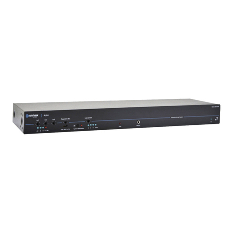
Edin Univox TLS-2.2 User manual

Technical manual and installation guide
Univox® TLS-2.2
Loop amplifier for railway use

2
Content
Safety 3
Univox TLS-2.2 - Introduction 3
Planning and setup of hearing loop systems on-board a train car 6
General information about loop systems 7
Background noise 7
Loop cable and its position 8
Installation 10
Univox setup procedure 14
Trouble shooting 16
General information 17

3
Safety
1. Please read this manual carefully before installing and operating the product
2. This manual shall always be available on-site, along with other technical
documentation
3. Do not install the unit near any heat sources such as radiators, heat registers, vents or
other apparatus that produce heat
4. Important! The unit must be mounted in such a way that the rear heat-sink overhangs
any flat surface onto which the unit is placed
5. Warning! The unit must be properly grounded by connecting the grounding terminal
(screw) located on the rear heat-sink to protective earth. The connection should be
established before taking the unit into operation
6. Power - There is no power switch on the unit. Isolate power supply externally before
removing any connections
7. In case the power to the unit must be interrupted, disconnect the 4-pin WAGO power
supply connector in the front panel
8. Do not make any modifications, extensions, or adaptations to the unit
9. All service and maintenance work must be performed by qualified personnel only
10. Never expose the unit to dripping or splashing, nor to liquid or moisture of any kind.
IP class 40
Univox TLS-2.2 - Introduction
Univox TLS-2.2 is an audio induction loop driver developed for hearing loop installations
in railway and other large vehicle applications. With its rugged and sophisticated design
TLS-2.2 ensures efficient and reliable operations in environments completely or partially
enclosed by metal, like train cars, trams, subways and ships.
TLS-2.2 provides high output current, up to 30 Arms, enabling compensation for the strong
damping effect that conductive materials may have on magnetic transmission. Metal loss
correction is also available for high frequency slope corrections.

4
There are several international standards within the railway industry that must be met
when installing electronic devices on-board rolling stock:
• EN 50121-3-2:2016+A1:2019 Railway applications - Electromagnetic compatibility
• EN 50155:2017 Railway applications - Electronic equipment used on rolling stock
• EN 61373:2010 Railway applications. Rolling stock equipment. Shock and
vibration tests
• EN 45545-2 Fire protection of railway vehicles - Part 2: Requirement for fire
behaviours of materials and components, HL2 (Hazard Level 2)
Univox TLS-2.2 has been tested against and fulfils the requirements in all the above
standards.
TLS-2.2 ha also passed the test for the following American standards:
• BSS 7239 - Toxic gas testing
• NFPA 130 - ASTM E162 testing of surface flammability and ASTM E 662 smoke
• FCC Regulations: Title 47, Chapter 1, Part 15 - EMC Emission
NOTE: This equipment has been tested and found to comply with the limits for a Class B
digital device, pursuant to part 15 of the FCC Rules. These limits are designed to provide
reasonable protection against harmful interference in a residential installation. This equip-
ment generates, uses and can radiate radio frequency energy and, if not installed and used
in accordance with the instructions, may cause harmful interference to radio communica-
tions. However, there is no guarantee that interference will not occur in a particular instal-
lation. If this equipment does cause harmful interference to radio or television reception,
which can be determined by turning the equipment off and on, the user is encouraged to
try to correct the interference by one or more of the following measures:
- Reorient or relocate the receiving antenna.
- Increase the separation between the equipment and receiver.
- Connect the equipment into an outlet on a circuit different from that to which the
receiver is connected.
- Consult the dealer or an experienced radio/TV technician for help.

5
Univox TLS-2.2 - driver
Front side - overview
Rear side - overview
219 mm 290 mm
86 mm
Weight: 2940g
Rugged WAGO con-
nectors for railway
applications
Input level LED
Input connector
Loop LED
Diagnostic output
connector
Power connector Power LED
Loop cable connector
Grounding screw for protective
earth connection
Chassis flanges
with screw holes
Large heat sink for
effective fan-free cooling

6
Overview of the different connections and connectors
Connector Function
description
Name Type Gender Pin signal Pin no. Voltage Current
J1-Loop WAGO
769662 Male Loop + 1 <35Vrms <30Arms Loop wire
connection
Loop - 2
J2-Power
and Diag.
WAGO
769-664 Male
D + 1 Open
collector 20mA Diagnostic
signal
D - 2 Emitter 20mA
P + 3
20-50V
<15ADC
125ms
peaks
LVPS +
P - 4 LVPS -
J3-Audio
input and
ground
WAGO
769-663 Male
Audio + 1 100mV-
5Vrms Audio input +
GND 2 Ground
Audio - 3 100mV-
5Vrms Audio input -
Planning and setup of hearing loop systems
on-board a train car
Summary
A successful installation should be planned carefully at an early stage. The challenging
installation environment in train cars, with different supply voltages, cramped space for
loop driver and loop cable location and ambiguous metal loss, calls for experience when
planning, installing and certifying loop systems on-board. Univox has extensive experience
since 1995 and our resources include in-house developed loop design soware, enabling
calculation, 2D and 3D simulation of field strength.
The initial step in the planning process is to create a test loop on-board of the vehicle.
Several important factors should be considered: loop figuration, detailed location of the
loop cable, cable type and cross-section and location of the loop driver. The information on
supplied mains power and signal level from the Passenger Information System (PIS) should
also be available.

7
With the test loop in place, the input sensitivity, loop output level and possible Metal Loss
Compensation (MLC) level, can be determined during an on-site measurement of the test
loop. If needed, adjustments to the loop figuration, loop cable location, cable type and
cross-section and location of the loop driver can be done at this point.
Once the appropriate input, output and MLC settings have been defined, all units intended
for the same project/train car type can be supplied with the correct preset levels to facilita-
te a fast and consistent installation process. A test loop measurement must be performed
separately for each train car type.
General information about loop systems
Current floating in a loop wire creates a directly proportional magnetic field. The magne-
tic field is picked up by a small copper coil (T-coil) integrated in most listening devices,
e.g. hearing aids, allowing the audio source to be transmitted directly to the hearing aid.
Magnetic background noise as well as recommended level, dynamic range and frequency
response of the field strength (FS), is specified in the IEC 60118-4 standard.
Background noise
At the start of any loop project, the magnetic background noise in the train car must be
measured and documented. This is done with a field strength meter (FSM). The background
noise level shall be measured at different positions in the train car (at the front, rear and
mid sections of the train car as well as in the aisle and at the seats). The background noise
levels may differ substantially between a train car standing still without power and the
same car moving in traffic, accelerating or braking. The most comprehensive picture of
the background noise levels is therefore achieved by measuring in all different operation
modes.

8
The IEC 60118-4 recommends a maximum magnetic background noise level of -22dB(A)
for announcements. With a stipulated field strength level of 0dB in the program peaks, this
equals a signal-to-noise (S/N) ratio of 22dB(A).
The PA speaker level in trains is normally specified for a S/N ratio of 15dB(A), i.e. the
speaker level is 15dB higher compared to the acoustic A-weighted ambient noise. Although
the IEC 60118-4 recommends a S/N ratio of 22dB(A) for the hearing loop system, there
is a note stating that a lower S/N ratio still might be beneficiary for the hearing aid users
in acoustically noisy environments. If the S/N ratio of the hearing loop system is higher
than the S/N ratio of the PA-system, the speech intelligibility for the hard of hearing will be
increased.
Loop cable and its position
Planning and installation of hearing loops in real environments, particularly in strong
metallic environments like trains, trams and boats, puts special focus on the choice of loop
cable, its impedance and placement. The chances to succeed in achieving an efficient sys-
tem is mostly based on extensive experience. Additionally, the chosen loop figuration has a
strong influence on both loop impedance and efficiency.
Choice of loop cable and loop load impedance
General: Loop impedance (Z), consisting of resistance (R) and reactance (XL) in series, are
essential parameters for optimal system performance. The final values depend on several
parameters. The goal is to achieve an impedance to match the driver’s dynamic large signal
behavior along with the speech spectrum . The resistance (R) should be kept as low as
possible for the highest efficiency.
The initial design should be based on 4 wires with 2.5-5mm2 cross-section area. Depending
on the application, it could be necessary to reduce the number of loop turns, reducing the
total impedance, thus making it easier to achieve the desired magnetic field strength level.
The inductance (L) is influenced by the cross-section of the wire, its length, the number
of turns and the metallic structure of the train car. All parameters can be calculated or
estimated, but it is a fairly complicated process for a complete practical design.

9
Location of loop cable
Metal
The loop wire should be placed as far as practically possible from any metal structures to
avoid excessive attenuation of the field strength. Even small variations in distance can in-
fluence the performance of the loop substantially. It is recommended to add some distan-
ces, whenever possible, to the metal chassis when altering the cable path. Door sections
are typical locations where distancing the loop wire could be possible.
Installation level/height
It is vital to achieve a certain difference between the loop level (i.e. the distance from the
floor where the loop cable is positioned) and the listening level (i.e. the distance from the
floor where the passenger’s hearing aids are positioned). For this reason, the loop cable
normally must be positioned either at floor level (or close to the floor) or at ceiling level (or
close to the ceiling). It should never be positioned too close to the listening level, which
is 1.2m from the floor for seated passengers and 1.7m from the floor for standing pas-
sengers.
In train cars with many seated passengers (medium- and long-distance train lines) a
listening level of 1.2m should be assumed. In these cases, the loop cable can be positioned
either at floor or ceiling level.
In train cars with a mix of seated and standing passengers (short-distance train lines, light
rail, subway and tram cars) a listening level of 1.45m should be assumed, accommodating
for both seated and standing passengers. In these cases, the loop cable must be positioned
at ceiling level.
Train car interior
In certain train cars the interior of the car may be used for housing of the loop cable. For
example, luggage racks or lighting ducts may be used. If those locations are chosen, a
careful study of how the metal in these structures may influence the performance of the
loop system.
On-site tests
Establishing the best position of the loop cable is a trial and error process and on-site tests
oen must be performed. Once determined for a specific train car type, all cars with the
same layout should use identical cable paths.
Signal cables
Avoid location of the loop cable closely in parallel to any signal cables to avoid inductive
coupling causing interference. This is especially important for analogue signals.

10
Installation
Location and installation of loop driver
The location of the loop amplifier should allow for easy access to available signal and the
power source. The TLS-2.2 driver can be mounted in any position (horizontal/vertical) using
the screw holes on the side flanges of the cover.
For the setting of input and output levels, the amplifier’s top cover must be removed. A
manual screwdriver should be used to avoid damaging the screws. When the installation
and setting of the loop system has been completed, the top cover must be refitted.
Note! The unit must be mounted in such a way that the heatsink overhangs the mounting
surface and is positioned “in free air”, allowing for proper ventilation/air flow. Failure to
comply with this requirement may result in unit overheating and shutting down prematu-
rely.
Power connection
Univox TLS-2.2 can be connected to either of two different power sources
• 24VDC direct power source
• A voltage stabilizing device, i.e. DC/DC converter with 24VDC out, that is connected to
any other voltage level present on-board (48, 72, 96 or 110VDC)
Since a DC power source may produce temporary voltage fluctuations, a voltage stabilizing
device, such as a DC/DC converter between the power source and the loop amplifier, may
be used, even when nominal voltage supplied is 24VDC. For any other power source volta-
ges, a DC/DC convertor is a requirement, due to the voltage limitations of the amplifier.
Low voltage power supplies (LVPS) need to be fused. Actual fuse specification is highly
dependent on the loop figuration. In a suggested figuration we estimate 8A (slow) will be
sufficient even for the most demanding loops. Univox TLS-2.2 has a non-retrigger fuse 10A
(slow) built into the unit. Quiescent current is approximately 50-100mA.
The cable used for connection to the 24VDC power source must have a cross-section of at
least 1mm2.
Note! As the incoming nominal voltage is 24VDC there is no risk of electrical shock if the
top cover is removed. Therefore, there is no need to disconnect the power supply before
removing the top cover.

11
Grounding
Signal ground (from PIS) and chassis ground must be kept galvanically separated to avoid
floating ground loops. The actual DC shi between the two ground systems needs to be
specified before installation, but must never exceed 1500VDC. To avoid any risk of damage
due to potential differences between the loop amplifier and other connected units, a floa-
ting output DC/DC converter is strongly recommended.
Tools and equipment
For connection of loop cable, signal and power source, and mounting of loop amplifier, the
following (common) installation tools are needed:
• Wire stripper
• Cutter
• Screwdrivers
• Screws and fasteners for mounting of the amplifier
• Soldering equipment
Other handy equipment:
• Flashlight
• Insulation tape
• Cable ties
Instruments:
• Multimeter for low resistance measurements
• Inductance meter
• Oscilloscope (normally not needed) with current clamp sensor.
Tools for measurement and listening:
Univox FSM Basic
or equivalent field
strength meter
Univox Listener
or equivalent field
strength meter

12
Signal source (from train PA system)
The TLS 2.2 input is galvanically isolated, fully balanced and low-pass filtered with common
mode transformer, to avoid EMI interference.
Recommended source signal: Low Ohmic (OP amplifier or such), fully balanced with a
quality screen.
Recommended input level: 0dBu=0.775Vrms according to audio standard (+4dBu will give
another 4dB noise headroom but the advantage is marginal). Default input DIP setting is
-16dB and -32dB switches in “ON” position, all remaining switches in “OFF” position.
Note 1: Speakers in high voltage line systems have normally a built-in transformer to tap
off the line-level to a low-ohmic speaker which in that case can be connected directly
to the TLS 2.2. The wire from the speaker must be screened. The level from a standard
low-ohmic speaker is normally less than 0dBu so the input sensitivity of the TLS 2.2 must
be adjusted accordingly.
Note 2: Higher voltage input levels, like from 100V speaker line system (not allowed
everywhere), can be connected by using a separate tapping transformer. Cable screen
should be connected to the chassis. However, if there is a voltage potential difference
between signal source screen and hearing loop transmitters screen/chassis, current will
float through the screen cable causing interference. In such cases the screen wire must be
disconnected at one side, normally at the signal source side.
A direct connection to the on-board speaker system is not possible due to the ampli-
fier’s input signal range. Even with a connected signal transformer between the TLS-2.2
unit and the PIS, such a connection is not recommended as the signal is processed for
the audio speaker system and will strongly affect the frequency response of the loop
system if used.
Input signal adjustment
The input signal level is adjusted at the DIP switch array marked ”Input” located on the PCB.
It consists of 8 switches, each representing an increasing attenuation of the input signal
with a fixed dB value:
0.25dB - 0.5dB - 1dB - 2dB - 4dB - 8dB - 16dB - 32dB

13
If all DIP switches are set to OFF (le position), no damping of the input signal will result.
However if for example the 16dB switch is set to ON, the input signal will be attenuated
by 16dB. If two or more DIP switches are set to ON, the combined damping effect of both
switches will occur. For example, if the 4dB and 8dB switches are set to ON, the resulting
damping effect will be 12dB.
Default settings (adjusted for an input signal level of 600mV):
0.25dB - 8dB = OFF 16 - 32dB = ON
Note! When adjusting the input signal level by setting the DIP switches, the input LED (In)
in the front panel will be activated first aer a short time period. The input LED will also
stay activated a longer time period aer deactivation of the input signal to facilitate moni-
toring of the system. This is intentional and not a fault.
Loop output
The loop output current is adjusted at the other DIP switch array on the PCB marked
”Loop”. It consists of 8 switches, each representing an increasing attenuation of the output
current with a fixed dB value:
0.25dB - 0.5dB - 1dB - 2dB - 4dB - 8dB - 16dB - 32dB
If all DIP switches are set to OFF (le position), no damping of the output loop current
will result. However, if for example the 16dB switch is set to ON, the output current will
be attenuated by 16dB. If two or more DIP switches are set to ON, the combined damping
effect of both switches will occur. For example, if the 4dB and 8dB switches are set to ON,
the resulting damping effect will be 12dB.
Default settings (no damping of the output current):
0.25dB - 32dB = OFF
Diagnostic output
TLS-2.2 can be connected to a computer host’s diagnostic system through the 20mA cur-
rent opto-coupler isolated outputs for control of input and/or output signals.

14
The typical set up for the initial train start-up procedure:
• When booting the on-board computer system an audio test signal activates the 20mA
current loop, to verify the function of the hearing loop systems
• The loop amplifier´s opto-coupler indicates if there is any loop output current, i.e. the
hearing loop driver transmits
• The opto-coupler’s indication is read by the computer and the result can be displayed
on the system screen to indicate the proper function of the loop system
The diagnostic output is activated through an isolated opto-coupler. Set the current
through the optical transistor to approximately 20mA current loop. The diagnostic out-
put’s D+ needs to be terminated by a suitable resistor to achieve the 20mA current loop.
If the connected power supply is 24VDC, the suitable resistor is 1.2kOhm (24VDC/20mA =
1.2kOhm).
Note! The diagnostic system does only indicate current floating in the loop, not that this
current and the resulting magnetic field strength is according to the IEC standard! This
must be ensured by pre-installation testing and setting of the loop systems’ input and
output level.
Univox setup procedure
The constant current function of TLS 2.2 is active over a wide impedance range, with
auto-adjustable gain versus loop load impedance. The loop system uses different levels
at different frequencies automatically. Using those facts, it is possible to find the highest
efficiency and field strength in the actual car including metal environment attenuation. See
the following Step by Step procedure for details.
Contact Univox whenever detailed calculations and further discussions are necessary.
Step by Step procedure
1. Select a suitable place for the loop driver, according to the above recommendations
2. Make sure that the amplifier’s ground screw at the heatsink is connected to protective
earth before starting the setup procedure
3. Remove the top cover to access the input and output DIP switch arrays on the PCB

15
4. Plan for the loop layout of the loop cable and its placement, considering all parameters
as discussed above and as described above
5. An initial test with a loop wire of 2.5-5mm2 using a 4-turn connection is recommended.
Select a cable practical for the installation, such as a flat wire with four conductors or
two twin-cables giving four conductors. The 4-turn loop can be considered as a large coil
with four turns
6. Connect the three WAGO mating connectors delivered with the driver to the
corresponding cables according to the above I/O overview:
a. 2-pol. WAGO 769-662 to the loop cable
b. 3-pol. WAGO 769-663 to the audio signal source
c. 4-pol. WAGO 769-664 to the power source and (if used) the diagnostic signal cable
7. Connect input signal source and loop cable to the loop driver’s input and output
connector. Note: For proper function a loop load must be connected to TLS-2.2
8. Connect the power supply – a standard laboratory DC power supply of 24V/10A is
sufficient at the initial test
9. Set all the output DIP switches to ”OFF” position
10. Set input DIP switches to: -16dB and -32dB to “ON” position, remaining to “OFF” position
11. Start the speech signal from the PA-system (0dBu) and verify that the input AGC LED
indicator is activated within a few seconds by the speech peaks
12. Output loop current LED indicator indicates whenever there is a current floating in the
loop wire
13. Note: if the loop wire is open circuit for some reason, the loop current LED indicator and
Optical Coupler indicator will not indicate transmission (no current is floating through the
loop)
14. Input signal LED-indicator and output loop current LED verifies the basic function of the
system
15. Simplest method to find a maximum level at different loop cable connections (cable
cross section area and the number of turns) is as follows:
a. Select a reference place, e.g. an aisle chair in the middle of the car, at approximately
1.2m (sitting) or 1.45m (between sitting and standing) above the floor level
b. Start with a 4-turn connection and document the highest peak level during a 15
second period. Document Field strength, Resistance (R) and Inductance (L)
c. Repeat the same procedure for 3-, 2- and 1-turn configuration. Choose the highest num-
ber of turns that will generate the highest Field strength level at the reference position

16
d. If there is no significant level difference when alternating the number of turns,
repeat the above installation procedure by using an oscilloscope (current clamp).
Set the output level accepting slightly clipping (rounding in current domain) in the
high-level speech peaks on each connection. Choose the highest number of turns that
will fulfil or give the highest level at the reference position
16. Use the MLC potentiometer to compensate for the metal influence in the high
frequency spectrum. If the MLC potentiometer has been used, always make sure that
an IEC 60118-4 compliant field strength level can still be achieved
17. The resulting setting of input, output and MLC levels will be used as the default setting
for all identical train cars within a project. In this way, no further level trimmings are
necessary at the serial installation, thereby securing consistent loop performance and
substantially reducing installation time and cost
Trouble shooting
Note: During the troubleshooting it might be necessary to verify signals by using an osci-
lloscope. Keep in mind that both loop outputs are floating. DO NOT connect the oscillos-
cope earth to any output as that will short the output to ground. Use the probe tip to look
separately at each output. One output has low level (around 50mV) and reflects outgoing
current. The other output reflects outgoing voltage (several volts).
Distortion at output voltage is normal for the constant current concept but there should
not be any visual distortion for the output current.
Basic trouble shooting scheme
Verify the following:
- Input AGC (Input LED) is activated
- Measure/listening equipment is not input clipping
- Measure/listening reference position and height is representative
- Measure/listening coil is in correct position and direction, considering the listening area
- Verify by listening (for >15 seconds) that the AGC system does not excessively increase
the level aer an announcement, due to too high input gain setting
Frequency response
1. The frequency response should be measured at approx. -12dB relative 400mA/m
(0dBL). Reduce the output current, NOT the input level, to approx. 100mA/m
(-12dBL). Readjust the output to the previous level. Proceed with frequency response
measurement. Aer this procedure adjust input sensitivity to the used program
material

17
2. High frequency response could be enhanced by creating a distance between the loop
wire and the metallic surface
3. The inductive reactance (XL) increases by the square of the number of turns of the
loop. Therefore, it could be necessary to decrease the number of turns to reduce the
impedance and thereby increase high frequency gain and reduce the risk of voltage
clipping
4. The Australian AS 1428.5-2010 standard is derived from the IEC 60118-4. However,
there are some significant differences:
- for strong metal reinforcement a larger level drop is accepted
- peak field strength level: -6dB for fast acting AGC
- field variation: -9dB to +3dB which is 6dB lower than IEC-recommendation (power
reduction of factor 4)
General information
Security/Warranty
Basic knowledge in audio installation techniques is required to achieve existing regulations.
The installer is responsible for the installation hereby avoiding any risk or cause of fire.
Please also note that warranty is not valid for any damage or defects on the product due to
incorrect or incautious handling.
Bo Edin AB shall not be held responsible or liable for interference to radio or TV equipment,
and/or to any direct, incidental or consequential damages or losses to any person or entity,
if the equipment has been installed by unqualified personnel and/or if installation instruc-
tions stated in the product Installation Guide have not been strictly followed.
Maintenance and care
The device should be kept clean to prevent excessive dust or other contaminants affecting
its operation. Under normal circumstances Univox products do not need any special main-
tenance. Should the unit become dirty, wipe the unit with a slightly damp cloth. Do not use
solvent or heavy cleaning agents.
Service
Should the system still not work aer trouble shooting, please contact the local distributor
of the product for further instructions. Always enclose a completed Service Form, see www.
univox.eu, Support.

18
Technical data
For additional information, please refer to product data sheet/brochure and CE certificate
which can be downloaded from www.univox.eu. If required, spare part lists or other techni-
Environment and recycling directives
Please follow existing disposal regulations. Thus, if you respect these instructions you
ensure human health and environmental protection.

19
Notes
_______________________________________
_______________________________________
_______________________________________
_______________________________________
_______________________________________
_______________________________________
_______________________________________
_______________________________________
_______________________________________
_______________________________________
_______________________________________
_______________________________________
_______________________________________
_______________________________________
_______________________________________
_______________________________________
_______________________________________

20
Bo Edin AB
Sweden and International Sales
+46 (0)8 767 18 18
www.univox.eu
tls-2-2-ig-gb • 190731 • Copyright © Bo Edin AB
Hearing excellence since 1965
Table of contents
Other Edin Amplifier manuals
Popular Amplifier manuals by other brands
MIA Laboratories
MIA Laboratories 413 TAPE SATURATOR user guide
Roland
Roland GP-100 Service notes
AUDIOropa
AUDIOropa PROLOOP C Operation instructions
Roksan Audio
Roksan Audio Kandy K2 BT user manual
Iron Age Audioworks
Iron Age Audioworks EQ H9 user manual
LEGRAND
LEGRAND ON-Q F7630 Instruction/installation sheet

