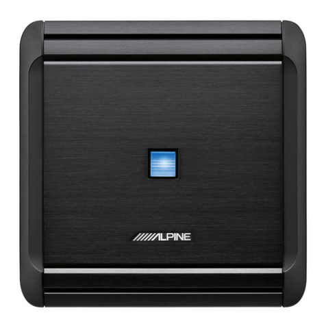
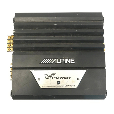
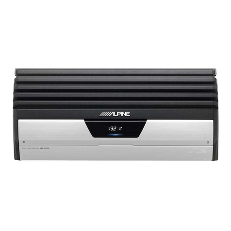
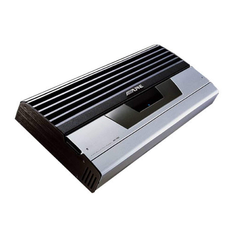
Alpine 3558 User manual

OWNER’S
MANUAL/BEDIENUNGSANLEITUNG/
MANUEL
DU
PROPRIETAIRE/MANUALE
DEL
PROPRIETARIO/
MANUAL
DEL
PROPIETARIO/BRUKSANVISNING
3558
4/3/2
Channel
Class
A
Power
Amplifier
ALPINE
asse
GLP
Cllennel
nbasr
A
owes
onpfor

Fig.
WAbb.1
oo
ee
ee
ek
eee
ee
oe
SWITCHES
AND
TERMINALS/SCHALTER
UND
ANSCHLUSSBUCHSEN/COMMUTATEURS
ET
BORNES/INTERRUTTOF
os
BAMA
NAEMINTERUITORES
Y
TERMINALES/OMKOPPLARE
OCH
ANSLUTNINGAR
rset
BORNES/INTERRUTTOR
;
Eig
DIABD
2a
ov
ee
ee
ye
ae
ee
on
pice
mary
-”
CONNECTIONS/ANSCHLUSSE/CON
EXIONS/COLLEGAMENTU/CONEXI
INES/ANSLUTNINGAR
See
Grease
ogg
Sec
S/ABb'S
5...
COE...
oo.
ONES/ANSLUTNINGAR
a5
:
“TYPICAL
SYSTEM
CONNECTIONS/TYPISCHE
ANSCHLUSSYSTEME/CONNEXIONS
DE
SYSTEME
TYPES/SISTEMI:
"
COLLEGAMENTO/SISTEMA
TIPICO
DE
CONEXIONES/TYPISKA
SYSTEMANSLUTNINGAR
TYPES/SISTEMI
aero!
SElG
G/ADD
6
(2
Sui
prec
Gt
ae
eh
oe
ee
Ee
Pye
Get
ek
ac
a
INSTALLATION/EINBAU/INSTALLATION/INSTALLAZIONE/INSTALACION/INSTALLATION
ee
“ENGLISH”:
FEATURES
fo.
ere
nea
penny
orb
eyiry
cee
PY
ety
one
ee
=
eae
SWITCHES
AND
TERMINALS
Oar
he
sees
oe
es
gee
Sd
ee
ACER
ee
SARE
Re
tetas
surenn
By
8
SVTECHES:
AND
TERMINALS.
1
+
esi
eres
Conia,
oe
ee
eee
10
PORNIEG
TIONG.
seer
ees
St
hide
teste
ota
cag
Actes
drt
ne
kn
ws
cial
ares
A
So
ge
tar
iy
Aird
ete
coal
oe
|
-
FAIR
IG
AM
vin
ciel
thas
cet
cay
ec
dce
tants
Ines
trem
nak
airaee
te
cakes
Cyne
Laken
&
ache
Mevuisaliks
Bead
_
BWR
SETTINGS
bec
cca
eck
hee
yh
oie
Direct
dn,
elec
Saeed
ci
Msdd
ban
rents
coe
a
Meal
ue
Ae
a
SPECIFICATIONS
wodrd=
ae
bo
uaan
ets
aaarsGutesmn
ga
oem
emne
in
adleeese
oh
hie
ce
teoles
mee
“DEUTSCH
MERRMOREs
hi
oes
2
olay
ee
oy
vie
ian
Aba
ede
ee
SCHALTER
UND-ANSCHLUSSBUCHSEN.........
000-0
0.c
cc
cec
cece
eeere
eee
cee
eben
debe
ep!
se?
VORSICHTSMASSNAHMEN.
.....
06...
0
ccc
cece
cee
cr
eee
e
beeen
ee!
i
RAPES
oe
Ae
ae
alt
Ne
get
dn
Aca
Mand
Scat
ay
Se
Le
OEY
g
WSS
tet
OREN
Nhe
TR
rte
KOPIN
ADAIR
AAS
Sead
sie
UP
DOERR:
Sie
Cit
TR
ENS
MPN
AS
ae
se
SOHAL
TEREINSTELCUNG
foun
ciao
na
eae
Leh
we
ties
arated
beh
Gkhearate
mabe
hi
uecten
ante
a
TECHNISCHE
DA
TEN
aes
clue
ati
a
Cacore
nacht
ber
eure
soerh
ne
bea
eerontgh
Gores
AANA
age
ek
Es
ae
“FRANCAIS”
CARACTERISTIQUES.........
oe
stds
nainai
etait
nase
*
COMMAUEATEURS
EF
BORNES
34,3,
Uathiags
TH
veh
e
suey
dbl
Ne
ok
Witt
£2
faa
ra
yum
euneciiate
tes
pe
COMMUTATEUROER
BORNES
cha.)
go
5h
otra
redid
caviiiya
Nur
ihiaa
ote
vam
sneRe
ene:
26
BONNE
IONS
ees
oe
noes
oe
ok
deel
wit
abtine
Ua
mtatik
ae
Geek
Ses
te
Pou
Nani
pail
int
Libtdie
2
cid
cae
(NERA
ION
io
Af
ivpoe
cee
F
Bega
sti
nae
ey
chris
hg
gto
ayo
ceng
cok
ed
4.
Sin
aan arn
hog
etd
tie
a
REGLAGE
DES
COMMUMATEURS
a
6
oo
oo
no
eatary
wry
ee
aan
aae
devia
Geran
eae
henna
oe
iG
.
SPECIFICATIONS
.
oc...
cure
see
a
nee
eee:
Sh
a
eden
data
Mra
GA8
dancin
Rea
eaee
ae
ae
“ITALIANO”
GARATVERISTICHE
22
aba
hice
Rai
eee
a
a
a
INTERRUTTORI
ETERMINALL
.............00
0c
cece
cece
eect
ebb
b
bbb bbb bbb
pre
eell,
eas
PRA
AOB
ce
oak
eee
dk
tse
ds
ioazconebreciocg
nat
a
eese
deed
Lae
vines
git
ane
cee
eles
hace
s
Polak
CRRNEN
GT
(oaed
Lock
as
Paon
tcs
buen
orc
yy
hoe
dak
Paks
abe
ete
baiche
wa
iis
6
hate
keke
shee
Seetate
og
|
ca
ING
TACEAZIONE:
econ
cad
cue
fcc:
Peet
cum
ts
tach
be
Pce
ta
ae
eee
Wick
ie
atta,
Ue
cealahc
dete
dey
aetna
ben
i
REGOLAZIONE
DEGLIINTERRUTTORI..
0...
0.
cece
eee
eee
cee
ce
eee
eee
eee
ee,
BB:
=e
SPECIFIC
AZION
ceracie
seats
Antes
nt
et
ern
af
ele
prea
taken
ge
hae
Wagers
Pad
sain
ton
bad
ap
te
Het
=
ses
“ESPANOL”
CARACTERISTICAS..........00
00-0
eeee
Predicts
tat
een
INTERRUPTORES
¥
TERMINALES.
..
.
fa
ssa
aescdevues
nee
gresdateeessdrenss
cena.
hich
s
bce
PRECAUCIONER
2
sls
Fu
leaed
andy
dee
bat
lee
uate
ote
tes
eked
Cee
ae
ie
ale
i
ie
CONE
IONE
Sy
ue
eine
Ao
a
bd
eaten
Lon
bale
hgaeein
boa
Bee
ee
Sheets
eae
ed,
bc
je
PGT
ACRCIORD
chal
cen
1
cc
esd
2
ses
9
|
doe
cadens
tie
mages
sot
cin
acd
mone
at
ahtga
ens
GcPS
Led
Ben
act
hae
ca
oe
Oy
INSTALADION
a
ale
sa
ete
Oe
asen
eae
aCe
CS
ee
he
tania
pidanie
tue
4A
SPEC
IICRCIONES
12252
oe.
0
Ga
Seen
adl
gk
twee
ee
oleemnane
eed
ad
Boma
kc
oy
oes
nee
“SVENSKA”
EGENSKAPER
.......00
0
cee
cece
eee
eeeeeueeseees
OMKOPPLARE
OCH
ANSLUTNINGAR
.........0
0000
cc
eee
cece
eee
eeewtebbbere
rebel
lee,
as
PORSICHGHE
TOR
IGAPDEI
ahr
coal
frccl
eegre
ahd
evan
ot
hele
yeias
ce
tmesetnk
cemeateat
cancunneo
kia’
oe
POISE
TINIG
AFA
4.
se
hes
op
che
acd
sede
x
Be
noe
thls
be
ok
tas
sks
tas
age
MAL
OM
te
hee
ce
co
a
Mies
scand
oho
=
PC
TREL
AMIN
cick
pi
bos
eetes
Gara
Bente
acne
d
eet
diesel
Ob
ead
yids
on
tu
hp
areMe
eit
chs
Ke
dacay
z
OMKOPPLARPOSITIONER
...........
0-0.
cece
cece
eee
e
le
eb bb
bbe
terete
tree
lee.
83.
a
SPE
GIFIOATIONE
A
pcker
e's
7a
c
eearectecachaiea
mindy
atone
gts,
4.
ata
ne
Mlua
aot
an
Nah
Gu
cata
e
guage
86
@
CHARACTERISTIC
CURVES/CHARAKTERISTISCHE
ENTZERRERKURVEN/COURBES
CARACTERISTIQUES/CURVE
CARATTERISTICHE/CURVAS
CARACTERISTICAS/FREKVENSKURVOR
87
@
SYSTEM
CHARTS/SYSTEMAUFBAU/DIAGRAMME
TOSIEMOVRISR
kan
ee
@
Remote
Turn-On
Lead
(Blue/White)
@
Speaker
Output
Lead
(Option)
@
Speaker
Output
T
inal
©
RCA
Input
Jacks
erminals
Fig.
2/Abb.
2
4

4-
Channel
‘System/4-Kanal-
yet
omnisucteie
a
|
A-canaux/Sistema
3
a
4-
onal:
-
/Sistema
de
4
canales/4-kanalssystem
4)
Remote
Turn-On
Lead
@
Front
Speakers
@®
Right
®ter
£
Cable
(Option)
Speakers
rs
®
Right
®
teft
8]
Head
Unit
with
Pre-Fader
Remote
Turn-On
Lead
Eee
@®
Mode
Selector
Switch
®
Input
Gain
Selector
Switch
CHEV]
BRIDGED
©.
STEREO
O
BRIDGED
(R)
()
aa
DIRECT
VARIABLE
CH
V4)
CH
(R)
STEREO
Uy
BRIDGED
2
=
pribsep
CH
Va)
DIRECT
VARIABLE
Fig.
3/Abb.
3
5
i
©
Battery
Lead
BS
@
Ground
Lead
9)
Extension
Cable
(Option)

3-Channel
System
(5-Channel
System
in
all)/3-Kanal-System
(5-Kanal-
-System
Gesamt)/Systéme
a
3-canaux
(Sistema
4
5-canaux
en
tout)/Sistema
a
3-
-canali
(Sistema
a
5-canali
in
tutto)/Sistema
de
3
canales
(Sistema
de
5
canales
en
~
total)/3-kanalssystem
(5-kanalsystem)
4)
Remote
Turn-On
Lead
=
@
Battery
Lead
@
Rear
BS
C
@
Ground
Lead
Speakers
©
Extension
Cable
{Option)
ami}
io
<f}
{em
-—-\
axgo)
<p
@®
Subwoofer
Speaker
ba
—~—————
Sy
ee
©
Head
Unit
®
Active
Dividing
AMP
@
Remote
with
Pre-Fader
Network
Turn-On
Lead
eset
®
Mode
Selector
Switch
®
Input
Gain
Selector
Switch
CH
[1/2]
one
DIRECT
VARIABLE
CH
a
DIRECT
VARIABLE
@
Front
Speakers
CH
BRIDGED
©
STEREO
©
BRIDGED
(R)
(L)
(R)
©
STEREO
ae
(L)
BRIDGED
RIDGED
a)
—
CH
[3](4]
Fig.
4/Abb.
4
6

2-Channel
System/2-Kanal-System/Systéme
a
2-canaux/Sistema
a
2-canali
/Sistema
de
2
canales/2-kanalssystem
@
Right
Speaker
AMP
(ED)
ome
2
z
wore
ee
yr
=
Boalt
ne
9
oct
ta
ouee.
3/4
@
Extension
Cable
(Option)
{|
[am
i!
@®
Mode
Selector
Switch
®
input
Gain
Selector
Switch
CH
fiz)
_—#!
4
DIRECT
VARIABLE
CH
Tt
DIRECT
VARIABLE
CH
eee
STEREO
0)
a
ho
(L)
BRIDGED
al
gehecn
©
STEREO
O
CH
[3i44]
Fig.
5/Abb.
5
7

_@
Ground
Lead
8)
Vehicle
Chassis
@
Mounting
Holes
~
Fig.
6/Abb.
6
CLASS
A
Class
A
operation
eliminates
switching
distortion
and
realizes
pure
sound
quality.
4/3/2
CHANNEL
OPERATION
The
3558
can
be
used
as:
a.
4-channel
amplifier,
producing
GOW
per
channel
into
4
ohms.
b.
3-channel
amplifier
producing
GOW
(4
ohms)
or
into
channels
1
&
2,
and
200W
(4
ohms)
into
the
third
channel.
c.
2-channel
amplifier,
producing
200W
per
channel
into
4
ohms.
STATUS
MONITOR
This
indicator
illuminates
in
green
when
the
amplifier
is
on
and
operational.
This
light
will
turn
orange
if
any
internal
protection
circuitry
is
activated.
MUTING
INDICATOR

DUAL
INDEPENDENT,
OPTICALLY
ISOLATED,
PWM
DC-TO-DC
SWITCHING
.
MODE
POWER
SUPPLIES
The
high
power
output
of
the
3558
is
achieved
through
the
use
of
a
pulse
width
|
modulation
power
source.
DUO-8&
FEEDBACK
CIRCUITRY
This
stabilizes
the
amplifier,
removes
DC
offset,
and
offers
excellent
total
harmonic
distortion
(T.H.D.)
characteristics.
It
also
provides
low
T.1.M.,
excellent.
slew
factor,
stability,
and
musicality.
NO
CURRENT
LIMITING
Absence
of
current
limiters
in
the
audio
section
ensures
low
T.I.M.,
excellent
transient
response,
and
superb
sonic
quality.
S.T.A.R.
CIRCUITRY
Alpine’
S
proprietary
Signal
Transit
for
Accurate
Response
circuit
topology
improves
sonic
properties
by
reducing
interaction
between
different
sections
of
the
circuitry.
MODE
SELECTOR
SWITCH
This
switch
allows
the
user
to
specify
the
input
signal
entering
the
amplifier.
DIRECT
INPUT
SWITCH
FULLY
DISCRETE,
COMPLEMENTARY
CIRCUITRY
DUAL
MODE,
FORCED
AIR
TUNNEL
COOLING
SYSTEM
INDEPENDENT,
CONTINUOUSLY
ADJUSTABLE
GAIN
CONTROLS
FOR
CH1
/2,
CH3/4
GOLD-PLATED
RCA
INPUT
CONNECTORS
GOLD-PLATED,
SCREW-DOWN
POWER
AND
SPEAKER
TERMINALS
HIGH
PERFORMANCE,
LOW
NOISE,
AUDIOPHILE
QUALITY
ACTIVE
AND
PASSIVE
COMPONENTS
EXTRA
HEAVY
DUTY
CONSTRUCTION

66606
66600
Q@OOeO
@
Refer
to
Fig.
1
on
page
3.
|
Power
Terminals
Ground
Lead
Terminal
Remote
On
Connector/STAND
BY
Connector
Fuse
Blocks
Speaker
Output
Terminals
(Channels
1/2)
Speaker
Output
Terminals
(Channels
3/4)
Input
Gain
Selector
Switch
(Channels
1/2)
Input
Gain
Adjustment
Control
(Channels
1/2)
Input
Gain
Selector
Switch
(Channels
3/4)
Input
Gain
Adjustment
Control
(Channels
3/4)
Input
RCA
Jacks
(Channels
1/2)
Input
RCA
Jacks
(Channels
3/4)
Mode
Selector
Switch
(Channels
1/2)
Mode
Selector
Switch
(Channels
3/4)
Mute
Indicator
Status
Monitor
Improper
wiring
connections
could
cause
damage
to
your
vehicle's
electrical
system
and/or
the
3558
amplifier.
Carefully
follow
the
wiring
instructions
in
this
manual.
Attaching
the
battery
lead
to
the
positive
(+)
terminal
of
the
battery
should
be
the
last
connection
after
all
other
connections
are
made.
Due
to
the
high
power
output
of
the
3558,
it
is
important
that
all
connections
are
clean
and
well
secured,
or
damage
could
result.
Be
sure
that
the
3558
is
mounted
in
a
way
that
will
allow
for
free
air
circulation
and
heat
dissipation.
When
changing
fuses,
be
sure
to
replace
the
old
fuse
with
one
of
the
same
amperage.
Use
of
improper
fuses
can
lead
to
serious
damage
to
components.
The
3558
amplifier
consumes
a
battery
current
of
5A
under
no
signal
condition
because
of
a
Class
A
type
amplification
circuit
used.
So
we
recommend
you
do
not
use
the
amplifier
under
the
engine
off
condition.
If
used
the
battery
will
be
wasted
rapidly.
,
40

Refer
to
Figs.
2
—
5
on
pages
4
—
7.
Before
making
connections,
be
sure
to
turn
the
power
off
to
all
audio
components.
Insulation
tubes
for
the
speaker
leads
and
the
power
supply
leads
are
supplied
with
the
3558,
route
the
speaker
leads
and
the
power
supply
leads
separately
through
these
tubes.
st)
Speaker
Output
Terminals
.
; ;
The
3558
has
two
sets
of
speaker
outputs
for
the
Front
and
Rear
speakers.
Be
sure
to
observe
correct
speaker
output
connections
and
phasing.
In
the
stereo
mode,
connect
the
right
speaker
output
to
the
right
speaker
and
the
left
to
left.
Connect
the
positive
output
to
the
positive
speaker
terminal
and
the
negative
to
negative.
In
the
bridged
mode,
connect
the
left
positive
to
the
positive
terminal
on
the
speaker
and
the
right
negative
to
the
negative
terminal
of
the
speaker.
Do
not
use
the
speaker
(—)
terminal
commonly
for
right
and
left
speakers
or
connect
it
to
the
vehicle's
chassis
ground.
NOTE:
12)
Do
not
connect
speaker
leads
together
or
to
chassis
ground.
Ground
Lead
(Black)
Connect
this
lead
securely
to
a
clean,
bare
metal
spot
on
the
vehicle’s
chassis.
Verify
this
point
to
be
a
true
ground
by
checking
for
continuity
between
that
point
and
the
negative
(—)
terminal
of
the
vehicle’s
battery.
Battery
Lead
(Yellow)
|
-»,
Connect
this
lead
directly
to
the
positive
(+)
terminal
of
the
vehicle's
battery.
Do
not
-
~»
connect
this
lead
to
the
vehicle’s
electrical
system.
oe
hy
2826888886
0000
Remote
Turn-On
Lead
(Blue/White)
Connect
this
lead
to
the
remote
turn-on
lead
of
your
head
unit.
RCA
Input
Jacks
Connect
these
jacks
to
the
line
out
leads
on
your
head
unit
using
RCA
extension
patch
cords.
Be
sure
to
observe
correct
channel
connections;
Left
to
Left,
Right
to
Right,
Front
to
Front,
and
Rear
to
Rear.
.
Insulation
Tube
Speaker
Output
Lead
Head
Unit
with
Pre-Fader
Extension
Cable
(Option)
Front
Speakers
Rear
Speakers
Mode
Selector
Switch
Subwoofer
Speaker
Head
Unit
with
Pre-Out
Left
Speaker
Right
Speaker
Active
Dividing
Network
Input
Gain
Selector
Switch
11

Refer
to
Fig.
6
on
page
8.
Due
to
the
high
power
output
of
the
3558,
considerable
heat
is
produced
when
the
amplifier
is
in
operation.
For
this
reason,
the
amplifier
should
be
mounted
in
a
location
which
will
allow
for
free
circulation
of
air,
such
as
inside
the
trunk:
For
alternate
installation
locations,
please
contact
your
authorized
Alpine
dealer.
1.
Using
the
amplifier
as
a
template,
mark
the
four
screw
locations.
a.
2.
Make
sure
there
are
no
objects
behind
the
surface
that
may
become
damaged
during
drilling.
3.
Drill
the
screw
holes.
4.
Position
the
3558
over
the
screw
holes,
and
secure
with
four
self-tapping
screws.
NOTES:
e
10
securely
connect
the
ground
lead,
use
an
already
installed
screw
on
the
metal
part
of
the
vehicle
(marked
(%*)
in
Fig.
6
on
page
8).
e
Mount
the
amplifier
in
a
location
which
do
not
obstruct
air
circulation
for
the
fan.
@
Self-Tapping
Screws
(M4
x
14)
@
Mounting
Holes
@)
Vehicle
Chassis
@
Ground
Lead
Mode
Selector
Switches
(3
and
a)
Set
to
the
"STEREO"
position
(center)
when
the
amplifier
is
used
as-a
4-channel
stereo
system.
STEREO
BRIDGED
BRIDGED
(R)
(L)
b)
Set
to
the
“VARIABLE”
and
“BRIDGED
(R)”
positions
when
the
amplifier
is
used
for
right
channel
of
bridged
system.
|
STEREO
DIRECT
VARIABLE
BRIDGED
BRIDGED
(R)
(L)
12

c).
Set
to.the
“VARIABLE”
and
“BRIDGED
(L)"
positions
when
the
amplifier
is
used
for
left
channel
of
bridged
system.
'
|
TEREO
DIRECT
VARIABLE
BRIDGED
—_—_—
BRIDGED
(R)
(L)
DIRECT/VARIABLE
Input
Selector
Switches
@®
and
@
a)
Set
to
the
“DIRECT”
position
when
connecting
the
3558
to
other
Alpine
products.
This
position
sets
the
input
sensitivity
to
500mV
which
corresponds
to
the
preamp
output
of
Alpine
products
when
the
amplifier
is
used
as
a
stereo
system.
Set
to
the
"\JARIABLE"
position
if
the
amplifier
is
used
for
bridged
system.
DIRECT
|
VARIABLE
b)
Set
to
the
“VARIABLE”
position
when
connecting
the
3558
to
a
non-Alpine
product
with
an
output
voltage
other
than
500mV.
This
position
should
also
be
used
when
.
adjustment
of
input
sensitivity
is
required
to
obtain
certain
imaging
requirements
or
to
compensate
for
different
speaker
efficiencies.
ee,
DIRECT
VARIABLE
Input
Gain
Adjustment
Controls
After
setting
your
head
unit's
volume
contro}
1/4
of
a
turn
down
from
the
maximum
output
level;
rotate
the
Input
Gain
Adjustment
Controls
®
and
@
with
a
#0
flat
blade
screwdriver
and
adjust
the
input
gain
to
the
point
where
there
is
maximum
volume
with
no
distortion.
Status
Monitor
This
indicator
lights
green
when
the
power
is
on.
The
3558
has
built-in
protection
circuitry.
lf,
for
some
reason,
this
protection
circuit
is
activated,
the
indicator
turns
orange.
lf
this
happens,
turn
the
system
off,
find
the
cause
of
the
problem
and
remedy
the
situation.
This
includes
checking
all
your
connections
and
wiring.
If
the
indicator
remains
orange
when
the
system
ig
turned
on,
consult
your
authorized
Alpine
dealer.
NOTE:
The
indicator
will
illuminate
in
orange
for
a
few
seconds
when
the
power
is
turned
on
as
the
protection
circuit
will
be
activated.
This
is
normal.
13

Mute
Indicator
The
Mute
indicator
©
will
illuminate
in
orange
for
10
seconds
just
after
the
power
of
the
head
unit
connected
to
this
amplifier
is
turned
on,
or
the
Status
Monitor
48
(protection
circuit
indicator)
is
turned
in
orange
for
some
reasons
or
the
cause
of
abnormality
is
released.
In
other
normal
conditions,
the
mute
indicator
will
illuminate
in
green.
The
amplifier
is
in
standby
condition
when
the
mute
indicator
illuminate
in
orange
and
no
sound
is
available
for
that
period.
STAND
BY
Connector
@®
When
the
STAND
BY
Connector
is
used
with
an
Alpine’s
head
unit
with
standby
display
function,
the
connector
allowing
the
head
unit
to
display
the
amplifier
is
in
standby
condition
when
the
amplifier
is
in
mute
mode.
a
s
When
the
connector
is
used
with
the
head
unit
with
standby
display
function,
use
the
Remote
On/Standby
connection
cable
supplied
with
the
head
unit.
14

Power
Output:
on
eee
4-Channel
Mode
....
40W
x
4
(into
4
ohms
with
0.02%
THD)
from
20 Hz
to
20
kHz
or
6OW
x
4
{into
4
ohms
with
10%
THD)
3-ChannelMode
.....
-,
4OW
x
2
{into
4
ohms
with
0.02%
THD)
from
20
Hz
to
20
kHz
or
BOW
x
2
(into
4
ohms
with
10%
THD)
and
~~
200W
x
1
(into
4
ohms
with
10%
THD)
2-Channel
Mode’
-.
0.
ce
ee
200W
x
2
(into
4
ohms
with
10%
THD)
Frequency
Responses
acide
idee
Caney
s
ewe
Ke
Sosa
t
Bia
10
Hz
to
90
kHz
(+0,
—-1
dB)
Signal-to-Noise
Ratio
.......
0.0.60
secs
e
eee
does
110
dBA
(referenced
to
rated
power)
Input
Sensitivity
(for
rated
power
output)
.....
6...
ee
Direct:
500mV
Variable:
100mV
—
2V
Input
Impedance
......
ee
ee
eh
dt
eee
hie
hae
athe
RP
aaa
tates
atte
47k
ohms
Speaker
Impedance
05).
4cc.
eases
2
cece
ee
aes
oS
ee
aegea
4
or
2
ohms
(stereo)
4
ohms
(bridged)
Power
REQUITEMERE:
oc
vseiiis
een
oad
Kes
a
hoes
Baw
ee
NO
11
—
16V
DC
Negative
Ground
Dimensions
WV
SCRIBD)
65
heh
dere
ottwatend
cet
Ronedes
232mm
x
73mm
x
400mm
(9-1/8"
x
2-7/8"
x
15-3/4")
NEEWIEIORE:
oc
Guthe
cretion
endorsed
ann
oveles
wclouewy
aha
eens
senso
eed.
be
Ibe
4.
OZ)
NOTE:
For
product
improvement,
specifications
and
design
are
subject
to
change
without
notice.
15

A-BETRIEB
Der
A-Betrieb
unterdruckt
alle
Schaltungsverzerrungen
und
sorgt
fur
eine
reine
Klangwiedergabe.
4/3/2
KANALBETRIEB
Der
3558
kann
verwendet
werden
als:
a.
4-Kanal-Vestarker
mit
6OW/Kanal
an
4
Ohm.
b.
3-Kanal-Verstarker
mit
GOW
(4
Ohm)
oder
an
Kanal
1
und
2,
und
200W
(4
Chm)
an
Kanal
3.
c.
2-Kanal-Verstarker
mit
200W/Kanal
as
4
Ohm.
STATUS-MONITOR
Diese
Anzeige
leuchtet
grin,
wenn
der
Verstarker
singescnaiet
und
betriebsbereit
ist.
Dieses
Licht
leuchtet
orange,
wenn
die
Schutzschaltung
anspricht.
ANZEIGE
STUMMSCHALTUNG
ZWEIFACHE
UNABHANGIGE,
OPTISCH
ISOLIERTE
GLEICHSPANNUNGS-
SCHALTNETZ-TEILE
Die
hohe
Leistungsabgabe
des
3558
wird
durch
Verwendung
einer
Pulsbreitenmodulation
erreicht.
DUO-&
RUCKKOPPLUNGSSCHALTUNG
Dies
stabilisiert
den
Verstarker,
beseitigt
Gleichstrom-Abweichungen
und
bietet
exzellente
Klirrverzerrungseigenschaften.
Es
bietet
ferner
niedrige,
schnellvergehende
intermodulationsfaktoren,
eine
exzellente
Einstellung,
Stabilitat
und
Musikalitat.
KEINE
STROMBEGRENZUNGEN
Die
Abwesenheit
von
Strombegrenzungen
im
Audioteil
garantiert
niedrige
Intermodulationsfaktoren,
exzellentes
Eiscnwingverallen
und
ausgezeichnete
Tonqualitat.
S.T.A.R.-SCHALTUNG
Die
Lésung
von
Alpine
fur
eine
Signalfuhrung
mit
optimalen
Resolution
verbessert
die
Tonqualitat
durch
Verminderung
der
Interferenzen
zwischen
den
Bereichen
der
Schaltung.
BETRIEBSARTENWAHLER
Dieser
Schalter
ermdglicht
dem
Benutzer,
das
Eingangssignal
zum
Verstarker
zu
bestimmen.
EINGANGSWAHLSCHALTER
ABSOLUT
DISKRETE,
KOMPLEMENTARE
SCHALTUNG
ZWEIFACHES
KUHLUNGSSYSTEM
MIT
LUFTFUHRUNG
16

@
UNABHANGIGE,
STUFENLOS
EINSTELLBARE
VERSTARKUNGSREGLER
FUR
CH1/2,
CH3/4
©
VERGOLDETE
RCA-EINGANGSANSCHLUSSE
@
VERGOLDETE,
ABSCHRAUBBARE
STROM-
UND
LAUTSPRECHERANSCHLUSSE
@
HOHE
LEISTUNGSFAHIGKEIT,
WENIG
GERAUSCHE,
AKTIVE
UND
PASSIVE
KOMPONENTEN
FUR
DIE
ZUHORQUALITAT
@
EXTRA
SCHWERE
KONSTRUKTION
17

Beziehen
Sie
sich
auf
Abb.
1
auf
Seite
3.
®
@
@
®
©
©
@.
®
®
D)
@O@09
@
Stromversorgungsanschlie
Erdungskabelanschlu&B
Fernsteuerung/Standby-Verbindung
Sicherung
Lautsprecher-Ausgangsanschlife
(Kanale
1/2)
Lautsprecher-Ausgangsanschlie
(Kanale
3/4)
Eingangsverstarkungsschalter
(Kanale
1/2)
Eingangsverstarkungs-Einstellregler
(Kanale
1/2)
Eingangsverstarkungsschalter
(Kanale
3/4)
Eingangsverstarkungs-Einstellregler
(Kanale
3/4)
RCA-Eingangsbuchsen
(Kandle
1/2)
RCA-Eingangsbuchsen
(Kandle
3/4)
Betriebsartenwahler
(Kanale
1/2)
Betriebsartenwahler
(Kanale
3/4)
Anzeige
Stummschaltung
Status-Monitor
Falsche
Anschliisse
kénnen
die
Elektrik
Ihres
Fahrzeuges
und/oder
den
Verstarker
3558
beschadigen.
Befolgen
Sie
die
Anschlufshinweise
in
dieser
Bedienungsanleitung
sorgfaltig.
Der
Anschliuf&
des
Batteriekabels
an
die
positive
(+)
Klemme
der
Batterie
sollte
erst
dann
erfolgen,
wenn
alle
anderen
Anschilsse
ausgefishrt
worden
sind.
Aufgrund
des
Hochspannungsausganges
des
3558,
ist
es
wichtig,
dag
alle
Anschliisse
sauber
und
abgesichert
sind,
da
es
ansonsten
zu
Beschadigungen
kommen
kann.
Achten
Sie
darauf,
daf§$
der
3558
so
installiert
wird,
daf§
eine
ausreichende
Luftzirkulation
und
Warmeabfuhr
vorhanden
ist.
Achten
Sie
beim
Austausch
von
Sicherungen
darauf,
dafS
die
neuen
Sicherungen
tiber
~
die
gleiche
Amperezahl
verfugen,
wie
die
ausgetauschten.
Die
Benutzung
von
falschen
Sicherungen
kann
zu
ernsthaften
Schaden
des
Gerates
fthren.
Der
Verstarker
3558
verbraucht
einen
Batteriestrom
von
weniger
als
5
Ampere
ohne
Ansteuerung,
weil
die
Verstarkungsschaltung
im
A-Betrieb
arbeitet.
Deshalb
empfehlen
wir
die
Benutzung
des
Verstarkers
nur
bei
laufendem
Motor,
da
andernfalls
die
Batterie
schnell
entladen
wird.
18

Beziehen
Sie
sich
Auf
Abb.
2
—
5
auf
Seite
4
—
7.
Vergewissern
Sie
sich
vor
dem
AnschlieBen,
daf
Sie
alle
Tonkomponenten
ausgeschaltet
haben.
|solationsschutzrohre
fiir
die
Lautsprecherkabel
und
Netzanschiufskabel
liegen
der
Lieferung
des
3558
bei.
Leiten
Sie
die
Lautsprecherkabel
und
die
Netzanschlukabel
getrennt
durch
diese
Rohre.
phewe
@
Lautsprecher-Ausgangsanschlife
Der
3558
besitzt
zwei
Paar
Lautsprecherausgange
fiir
Vorder-
und
Ruckwartige
Lautsprecher.
Beachten
Sie
bitte
den
korrekten
Anschlu&
und
die
richtige
Polung.
SchlieBen
Sie
in
der
Stereo-Betriebsart
den
rechten
Lautsprecherausgang
an
den
rechten
Lautsprecher
und
den
linken
Lautsprecherausgang
an
den
linken
Lautsprecher
an.
SchlieBen
Sie
den
positiven
Ausgang
an
die
positive
Lautsprecherklemme
und
den
negativen
Ausgang
an
die
negative
Lautsprecherklemme
an.
SchlieRen
Sie
in
der
tiberbriickten
Betriebsart,
schlieRen
Sie
den
linken
positiven
Ausgang
an
die
positive
Klemme
des
Lautsprechers
an,
und
den
rechten
negativen
Anschluf$
an
den
negativen
Anschlu
des
Lautsprechers
an.
Verwenden
Sie
den
Lautsprecheranschlu&
(—)
nicht
als
Masseverbindung
fir
linke
oder
rechte
Lautsprecher.
Verbinden
Sie
inn
nicht
mit
dem
Chassis
als
Masse.
HINWEIS:
SchlieRen
Sie
die
Lautsprecherkabel
nicht
zusammen
oder
an
die
Fahrzeuggestellerdung
an.
@
Erdungskabel
(schwarz)
Schliefen
Sie
dieses
Kabel
sicher
an
eine
saubere,
aus
reinem
Metall
bestehende
Stelle
am
Fahrzeugchassis
an.
Vergewissern
Sie
sich,
da®
es
sich
bei
der
ausgewahlten
Stelle
wirklich
um
einen
fur
die
Erdung
geeigneten
Punkt
handelt,
indem
Sie
die
Kontinuitat
zwischen
dieser
Stelle
und
dem
negativen
(—)
Anschlufs
der
Autobatterie
Uberprufen.
®©
Batteriekabel
(gelb)
.
:
-SchlieRen
Sie
dieses
Kabel
direkt
an
den
positiven
(+)
Anschluf
der
Autobatterie
an.
Der
Anschlu&
darf
keinesfalls
dort
erfolgen,
wo
das
elektrische
System
des
Fahrzeuges
verdrahtet
ist.
@
Ferneinschaltkabel
(blau/weif)
SchlieBen
Sie
dieses
Kabel
an
die
Ferneinschaltkabel
Ihres
Hauptgerates
an.
RCA-Eingangsbuchsen
Verbinden
Sie
diese
Buchsen
mit
den
Ausgangsbuchsen
Ihres
Steuergerates
mittels
RCA-Verlangerungskabel.
Achten
Sie
dabei
auf
die
richtigen
Kanalanschlusse:
links
an
links,
rechts
an
rechts,
vorn
an
vorn
und
hinten
an
hinten.
®
Isolationsrohr
Lautsprecher
Ausgangskabel
Steuergerat
mit
Pre-Fader
Verlangerungskabel
(als
Option)
Vorder-Lautsprecher
Riickwartige-Lautsprecher
Betriebsartenwahler
Subwoofer-Lautsprecher
Steuergerat
mit
Pre-Out
Linker
Lautsprecher
Rechter
Lautsprecher
Aktiven
Frequenzweichen
Eingangsverstarkungschalter
20266883886
06900
19

Beziehen
Sie
sich
auf
die
Abb.
6
auf
Seite
8.
Aufgrund
des
hohen
Stromausgangs
des
3558,
wird
beim
Betrieb
des
Verstarkers
eine
betrachtliche
W&rme
erzeugt.
Aus
diesem
Grund,
sollte
der
Verstarker
an
einem
Ort
montiert
werden,
die
eine
freie
Luftzirkulation
erlaubt,
wie
z.B.
im
Inneren
des
Kofferraum.
Hinsichtlich
weiterer
méglicher
Installationsorte,
kontaktieren
Sie
bitte
lhren
authorisierten
Alpine-Handler.
1.
Benutzen
Sie
den
Verstarker
als
Schablone,
um
die
4
Schraubstellen
zu
markieren.
2.
Uberprtifen
Sie,
da®
sich
hinter
der
Oberflache
keine
Gegenstande
befinden,
die
durch
das
Bohren
beschadigt
werden
kénnten.
3.
Bohren
Sie
die
Schraublécher.
4.
Bringen
Sie
den
3558
Uber
die
Locher
in
Position
und
sichern
Sie
ihn
mit
4
Blechschrauben.
HINWEISE:
e
Um
das
Erdungskabel
sicher
zu
befestigen,
verwenden
Sie
eine
bereits
an
einem
Metallteil
des
Fahrzeugs
installierte
Schraube
(mit
(%*)
markiert
auf
Abb.
6
auf
Seite
8).
e
eee
des
Verstarkers
an
einer
Stelle,
die
die
Lutfbewegung
des
Ventilators
nicht
ehindert.
@
Blechschrauben
(M4
x
14)
@
Aufbaulécher
@®
Fahrzeugchassis
@
Erdungskabel
Betriebsartenwa&hler
@
und
a)
Einstellen
auf
“STEREO”
(Mitte)
wenn
der
Verstarker
als
4-Kanal
miereosyotern
verwendet
wird.
a
a]
STEREO
BRIDGED
BRIDGED
(R)
(L)
b)
Einstellen
auf
“VARIABLE”
und
“BRIDGED
(R)”
wenn
der
Verstarker
in
Bruckenschaltung
auf
den
rechten
Kanal
arbeiten
soll.
alt
|
STEREO
|
DIRECT
VARIABLE
BRIDGED
BRIDGED
(R)
(L)
20
Table of contents
Languages:
Other Alpine Amplifier manuals

Alpine
Alpine 3519 User manual

Alpine
Alpine 35278 User manual

Alpine
Alpine Jaguar 6W83-18C808-AB User manual

Alpine
Alpine PDX-2.150 User manual

Alpine
Alpine 3554 User manual

Alpine
Alpine PXE-0850S User manual

Alpine
Alpine MRV-F545 User manual

Alpine
Alpine MRP-M850 User manual

Alpine
Alpine PDX-M6 User manual

Alpine
Alpine MRP-F240 User manual

Alpine
Alpine MRX-F65 User manual

Alpine
Alpine PDX-M12GC User manual

Alpine
Alpine PDX-4 - Amplifier User manual

Alpine
Alpine PDP-E800DSP User manual

Alpine
Alpine PDX11000 - Amplifier User manual

Alpine
Alpine MRV-T320 User manual

Alpine
Alpine PDX-4.100 User manual

Alpine
Alpine PDX-M6 User manual

Alpine
Alpine MRX-M55 User manual

Alpine
Alpine S-A60M User manual