- 2 -
Warning
To avoid possible electric shock or personal
injury, and to avoid possible damage to the Meter or
to the equipment under test, adhere to the following
rule s:
¾Before using the Meter inspect the case. Do
not use the Meter if it is damaged or the case
(or part of the case) is removed. Look for
cracks or missing plastic. Pay attention to
the insulation around the connectors.
¾Inspect the test leads for damaged insulation
or exposed metal. Check the test leads for
continuity.
¾Do not apply more than the rated voltage, as
marked on the Meter, between the terminals or
between any terminal and grounding.
¾The rotary switch should be placed in the right
position and no any changeover of range shall
be made during measurement is conducted to
prevent damage of the Me ter.
¾When the Meter working at an effective voltage
ove r 60V in DC or 30V rms in AC, special care
should be taken for there is danger of electric
shock.
¾Use the proper terminals, function, and range
for your measurements.
¾Do not use or store the Meter in an
environment of high temperature, humidity,
explosive, inflammable and strong magnetic
field. The performance of the Meter may
deteriorate after dampened.
¾When using the test leads, keep your fingers
behind the finger guards.
¾Disconnect circuit power and discharge all
- 3 -
high-voltage capacitors before testing
resistance, continuity, diodes.
¾Replace the battery as soon as the battery
indicator
appears. With a low battery,
the Meter might produce false readings that
can lead to electric shock and personal injury.
¾Remove the connection between the testing
leads and the circuit being tested, and turn the
Meter power off before opening the Meter
case.
¾When servicing the Meter, use only the same
model number or identical electrical
specifications replacement parts.
¾The internal circuit of the Meter shall not be
altered at will to avoid damage of the Meter
and any accident.
¾Soft cloth and mild detergent should be used
to clean the surface of the Meter when
servicing. No abrasive and solvent should be
used to prevent the surface of the Meter from
corrosion, damage and accident.
¾The Meter is suitable for indoor use.
¾Turn the Meter power off when it is not in use
and take out the battery when not using for a
long time. Constantly check the battery as it
may leak when it has been using for some time,
replace the battery as soon as leaking appears.
A leaking battery will dam age the Mete r.
- 5 -
ķTransformer Jaws
Pick up the AC Current flowing through the conductor
ĸTrigge r
Press the level to open the transformer jaws when the
finger press on the level is released the jaws will close
again.
ĹData Hold Switch
A push switch (pushes on, push off, do not pull to select
function). All function and ranges with this feature.
ĺRotary Switch
A rotary switch is used to select measurement Function
and Range switch.
ĻDisplay
3 ½ digits (1999 counts), decimal point, minus polarity,
Over range and “ ” indicators.
ļEXT Input Connect
Used for accept insulation tester unit EXT banana plugs,
when measurement insulation resistance.
ĽCOM Input Connect
Low input for all voltage, resistance, and continuity
measurement will accept banana plugs. When
measurement insulation resistance, used for accept
insulation tester unit COM banana plugs.
ľ9,QSXW&RQQHFW
High input for all voltage, resistance, and continuity
measurement will accept banana plugs. When
measurement insulation resistance, used for accept
insulation WHVWHUXQLW9EDQDQDSOXJV
ĿDrop-Proof Wrist Strap
Prevents the instrument from slipping off the hand while
in use.
- 6 -
General Specifications
Max display: LCD 3 ½ digits, 1999 counts, 0.5” high
Polarity: Automatic, indicated minus, assumed plus.
Measure method: double integral A/D switch
implement
Sampling speed: 2 times per second
Over-load indication: “1” is displayed
Operating Environment: 0ć~40ć, at <80%RH
Storage Environment: -10ć~50ć, at <85%RH
Power: 9V NEDA 1604 or 6F22
Low battery indication: “ ”
Static electricity: about 4mA
Product Size: 230×68×37mm
Product net weight: 240g (including battery)
Technical Specifications
Accuracies are guaranteed for 1 year, 23ć±5ć, less
than 80%RH
DC VOLTAGE
RANGE RESOLUTION ACCURACY
1000V 1V ±(1.0% of rdg + 5D)
OVERLOAD PROTECTION: 1000V DC or 750V rms
for all ranges.
AUDIBLE CONTINUITY
Built-in buzzer sounds if resistance is
OHVVWKHQȍ
OVERLOAD PROTECTION: 15 second maximum
250V rms.
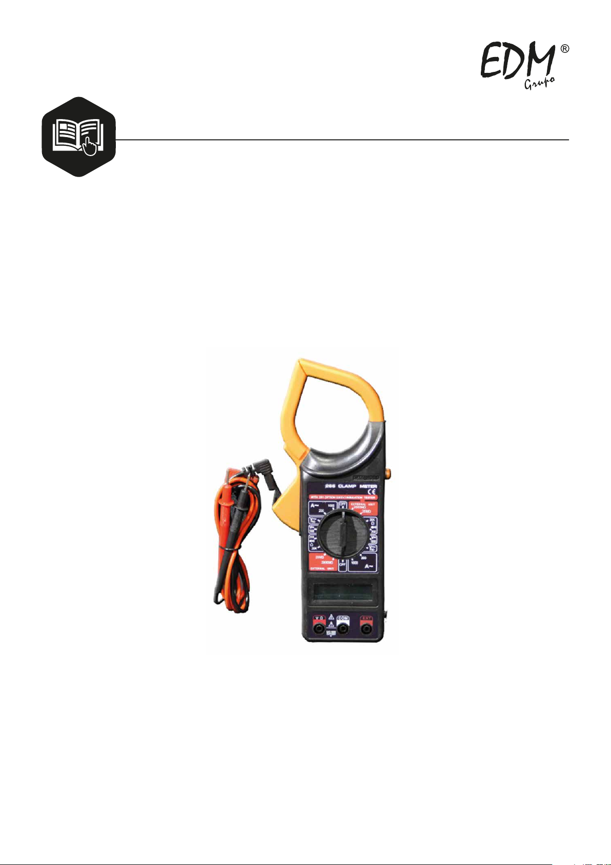
OPERATOR’S
INSTRUCTION
MANUAL
READ AND UNDERSTAND THIS MANUAL
BEFORE USING THE INSTRUMENT.
RANGE RESOLUTION ACCURACY
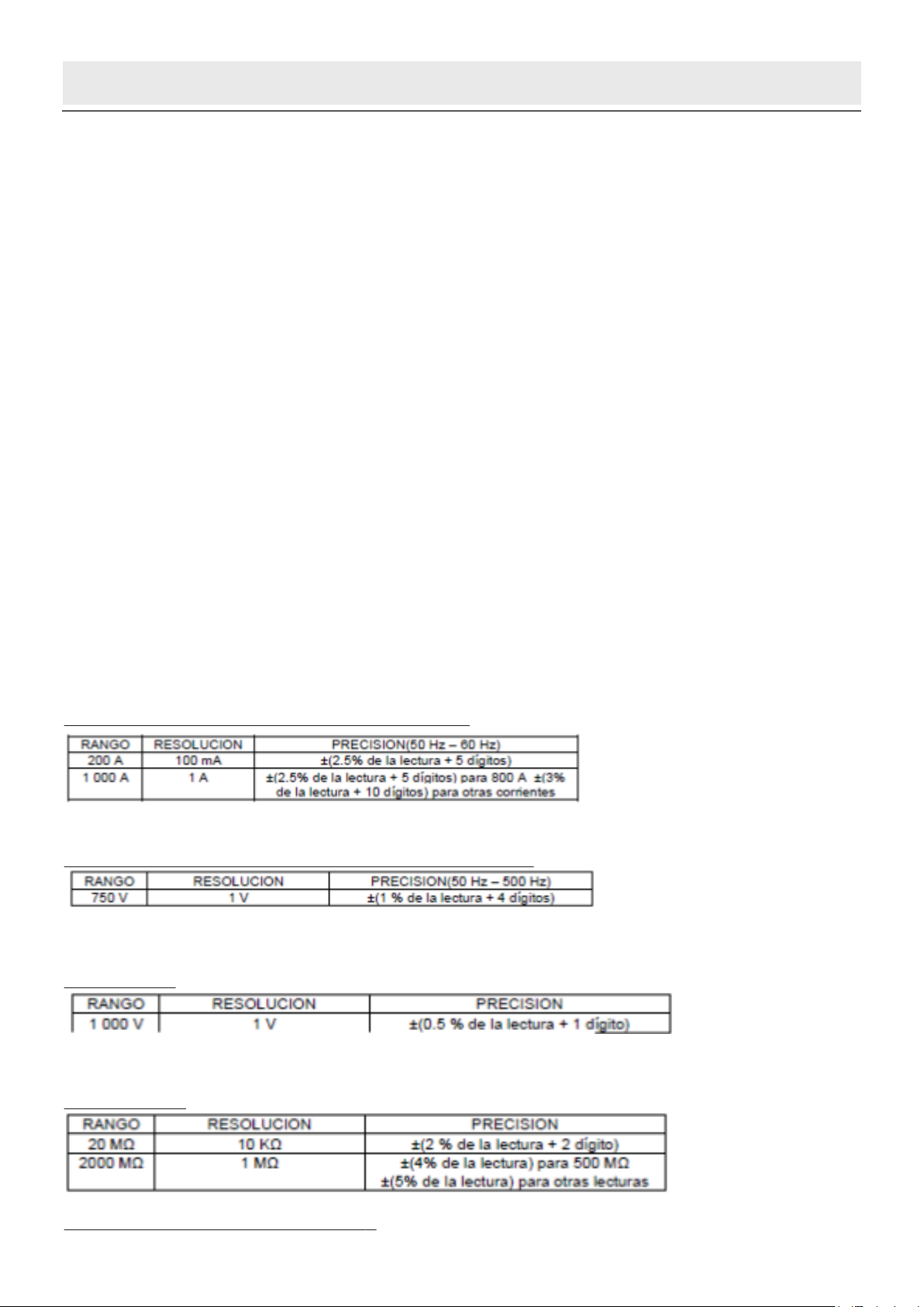
750V 1V ±(1.2% of rdg +5D)
RESPONSE: Average responding, calibrated in rms
of a sine wave.
FREQUENCY RANGE: 45Hz ~ 450Hz
OVERLOAD PROTECTION: 1000V DC or 750V rms
for all ranges.
AC Current (Average sensing, calibrated to rms
of sine wave)
Ragnge Resolution Accuracy (50Hz ~ 60Hz)
200A 100mA ±(2.5% + 13)
±(2.5% + 8)
for 800A and below
the reading is only for reference
for more than 800A
Overload Protection: 1200A within 60 seconds.
Jaw Opening: 2.09” (53mm)
Insulation Test (With option 500V insulation
tester unit)
Ragnge Resolution Accuracy
0ȍ .ȍ ±(2% + 2)
±(4% + 2)
IRU0ȍDQGEHORZ
±(5% + 2)
for others
RANGE RESOLUTION ACCURACY
ȍ ȍ ±(1.0% of rdg +10D)
.ȍ ȍ ±(1.0% of rdg +4D)
MAXIMUM OPEN CIRCUIT VOLTAGE: 3V.
OVERLOAD PROTECTION: 15 seconds maximum
250Vrms.
OPERATING INSTRUCTIONS
AC CURRE NT MEASURE
1. Make sure that “Data Hold” Switch is no pressed.
2. Set Range Switch to the ACA 1000A range. If the
display indicates one or more leading zeros. Shift
to the 200A range to improve the resolution of the
measurement.
3. Press the trigger to open the transformer jaws
and clamp one conductor only it is impossible to
make measurements when two or three
conductors are clamped at the same time.
4. Display reading is flow the conductor AC current.
INSULATION RESISTANCE TESTER
1. Set Range Switch to the insulation tester
0UDQJH7KLVFRQGLWLRQWKHGLVSOay value
is unstable that is normal.
2. 7KH LQVXODWLRQ WHVWHU XQLW 9-COM-EXT three
banana plugs insert to clamp meter
9-COM-EXT three input connector.
3. Set the insulation tester unit range switch to the
0SRVLWLRQ
4. Use the insulation tester unit of the test leads
- 9 -
connect its L-E input connect to being tested
installation’s (test installation’s must be power off)
5. Set the insulation tester power switch to the ON
position.
6. Depress the PUSH 500V push-push switch, the
500V on red LED lamp will light. Clamp mete r
display reading is the insulation resistance value
LI WKH UHDGLQJ LV EHORZ 0 FKDQJH FODPS
PHWHU DQG LQVXODWLRQ WHVWHU XQLW WR 0 UDQJH
can be increase the accuracy.
7. If the insulation tester unit is not use the power
switch must shift to power OFF position, and the
test leads must leave the E-L input connect, that
can be increase battery life and prevent electrical
shock hazard.
DC & AC VOLTAGE MEASUREMENT
1. &RQQHFWUHGWHVWOHDGWR³9ȍ´MDFN%ODFNOHDGWR
³&20´MDFN
2. Set RANGE switch to desired VOLTAGE position,
if the voltage to be measured is not known
beforehand, set switch to the highest range and
reduce it until satisfactory reading is obtained.
3. Connect test leads to device or circuit being
measured.
4. Turn on power of the device or circuit being
measured voltage value will appear on Digital
Display along with the voltage polarity.
RESISTANCE MEASUREMENT
1. 5HGOHDGWR³9ȍ´%ODFNOHDGWR³&20´
- 10 -
2. RANGE switch to desired ȍposition.
3. If the resistance being measured is connec- ted to
a circuit, turn off power and discharge all
capacitors before measurement.
4. Connect test leads to circuit being measured.
5. Read resistance value on Digital Display.
AUDIBLE CONTINUITY TEST
1. Red lead to “Vȍ”, Black lead to “COM”.
2. RANGE switch to “ ” position.
3. Connect test leads to two points of circuit to be
tested. If the resistance is lower then 30ȍ±ȍ,
the buzzer will sound.
BATTERY REPLACEM ENT
If “ ” appears in display, it indicates that the
battery should be replaced.
ACCESSORIES
¾Operator’s instruction manual
¾Set of test leads
¾Gift box
¾9-volt battery, NEDA 1604 6F22 type.
Ͼ⠜䴶
᥋Շ䨿(9[PPϾ⠜䴶 ষ
- 2 -
Warning
To avoid possible electric shock or personal
injury, and to avoid possible damage to the Meter or
to the equipment under test, adhere to the following
rule s:
¾Before using the Meter inspect the case. Do
not use the Meter if it is damaged or the case
(or part of the case) is removed. Look for
cracks or missing plastic. Pay attention to
the insulation around the connectors.
¾Inspect the test leads for damaged insulation
or exposed metal. Check the test leads for
continuity.
¾Do not apply more than the rated voltage, as
marked on the Meter, between the terminals or
between any terminal and grounding.
¾The rotary switch should be placed in the right
position and no any changeover of range shall
be made during measurement is conducted to
prevent damage of the Me ter.
¾When the Meter working at an effective voltage
ove r 60V in DC or 30V rms in AC, special care
should be taken for there is danger of electric
shock.
¾Use the proper terminals, function, and range
for your measurements.
¾Do not use or store the Meter in an
environment of high temperature, humidity,
explosive, inflammable and strong magnetic
field. The performance of the Meter may
deteriorate after dampened.
¾When using the test leads, keep your fingers
behind the finger guards.
¾Disconnect circuit power and discharge all
- 3 -
high-voltage capacitors before testing
resistance, continuity, diodes.
¾Replace the battery as soon as the battery
indicator
appears. With a low battery,
the Meter might produce false readings that
can lead to electric shock and personal injury.
¾Remove the connection between the testing
leads and the circuit being tested, and turn the
Meter power off before opening the Meter
case.
¾When servicing the Meter, use only the same
model number or identical electrical
specifications replacement parts.
¾The internal circuit of the Meter shall not be
altered at will to avoid damage of the Meter
and any accident.
¾Soft cloth and mild detergent should be used
to clean the surface of the Meter when
servicing. No abrasive and solvent should be
used to prevent the surface of the Meter from
corrosion, damage and accident.
¾The Meter is suitable for indoor use.
¾Turn the Meter power off when it is not in use
and take out the battery when not using for a
long time. Constantly check the battery as it
may leak when it has been using for some time,
replace the battery as soon as leaking appears.
A leaking battery will dam age the Mete r.
- 4 -
- 5 -
ķTransformer Jaws
Pick up the AC Current flowing through the conductor
ĸTrigge r
Press the level to open the transformer jaws when the
finger press on the level is released the jaws will close
again.
ĹData Hold Switch
A push switch (pushes on, push off, do not pull to select
function). All function and ranges with this feature.
ĺRotary Switch
A rotary switch is used to select measurement Function
and Range switch.
ĻDisplay
3 ½ digits (1999 counts), decimal point, minus polarity,
Over range and “ ” indicators.
ļEXT Input Connect
Used for accept insulation tester unit EXT banana plugs,
when measurement insulation resistance.
ĽCOM Input Connect
Low input for all voltage, resistance, and continuity
measurement will accept banana plugs. When
measurement insulation resistance, used for accept
insulation tester unit COM banana plugs.
ľ9,QSXW&RQQHFW
High input for all voltage, resistance, and continuity
measurement will accept banana plugs. When
measurement insulation resistance, used for accept
insulation WHVWHUXQLW9EDQDQDSOXJV
ĿDrop-Proof Wrist Strap
Prevents the instrument from slipping off the hand while
in use.
- 6 -
General Specifications
Max display: LCD 3 ½ digits, 1999 counts, 0.5” high
Polarity: Automatic, indicated minus, assumed plus.
Measure method: double integral A/D switch
implement
Sampling speed: 2 times per second
Over-load indication: “1” is displayed
Operating Environment: 0ć~40ć, at <80%RH
Storage Environment: -10ć~50ć, at <85%RH
Power: 9V NEDA 1604 or 6F22
Low battery indication: “ ”
Static electricity: about 4mA
Product Size: 230×68×37mm
Product net weight: 240g (including battery)
Technical Specifications
Accuracies are guaranteed for 1 year, 23ć±5ć, less
than 80%RH
DC VOLTAGE
RANGE RESOLUTION ACCURACY
1000V 1V ±(1.0% of rdg + 5D)
OVERLOAD PROTECTION: 1000V DC or 750V rms
for all ranges.
AUDIBLE CONTINUITY
Built-in buzzer sounds if resistance is
OHVVWKHQȍ
OVERLOAD PROTECTION: 15 second maximum
250V rms.
OPERATOR’S
INSTRUCTION
MANUAL
READ AND UNDERSTAND THIS MANUAL
BEFORE USING THE INSTRUMENT.
RANGE RESOLUTION ACCURACY
750V 1V ±(1.2% of rdg +5D)
RESPONSE: Average responding, calibrated in rms
of a sine wave.
FREQUENCY RANGE: 45Hz ~ 450Hz
OVERLOAD PROTECTION: 1000V DC or 750V rms
for all ranges.
AC Current (Average sensing, calibrated to rms
of sine wave)
Ragnge Resolution Accuracy (50Hz ~ 60Hz)
200A 100mA ±(2.5% + 13)
±(2.5% + 8)
for 800A and below
the reading is only for reference
for more than 800A
Overload Protection: 1200A within 60 seconds.
Jaw Opening: 2.09” (53mm)
Insulation Test (With option 500V insulation
tester unit)
Ragnge Resolution Accuracy
0ȍ .ȍ ±(2% + 2)
±(4% + 2)
IRU0ȍDQGEHORZ
±(5% + 2)
for others
RANGE RESOLUTION ACCURACY
ȍ ȍ ±(1.0% of rdg +10D)
.ȍ ȍ ±(1.0% of rdg +4D)
MAXIMUM OPEN CIRCUIT VOLTAGE: 3V.
OVERLOAD PROTECTION: 15 seconds maximum
250Vrms.
OPERATING INSTRUCTIONS
AC CURRE NT MEASURE
1. Make sure that “Data Hold” Switch is no pressed.
2. Set Range Switch to the ACA 1000A range. If the
display indicates one or more leading zeros. Shift
to the 200A range to improve the resolution of the
measurement.
3. Press the trigger to open the transformer jaws
and clamp one conductor only it is impossible to
make measurements when two or three
conductors are clamped at the same time.
4. Display reading is flow the conductor AC current.
INSULATION RESISTANCE TESTER
1. Set Range Switch to the insulation tester
0UDQJH7KLVFRQGLWLRQWKHGLVSOay value
is unstable that is normal.
2. 7KH LQVXODWLRQ WHVWHU XQLW 9-COM-EXT three
banana plugs insert to clamp meter
9-COM-EXT three input connector.
3. Set the insulation tester unit range switch to the
0SRVLWLRQ
4. Use the insulation tester unit of the test leads
- 9 -
connect its L-E input connect to being tested
installation’s (test installation’s must be power off)
5. Set the insulation tester power switch to the ON
position.
6. Depress the PUSH 500V push-push switch, the
500V on red LED lamp will light. Clamp mete r
display reading is the insulation resistance value
LI WKH UHDGLQJ LV EHORZ 0 FKDQJH FODPS
PHWHU DQG LQVXODWLRQ WHVWHU XQLW WR 0 UDQJH
can be increase the accuracy.
7. If the insulation tester unit is not use the power
switch must shift to power OFF position, and the
test leads must leave the E-L input connect, that
can be increase battery life and prevent electrical
shock hazard.
DC & AC VOLTAGE MEASUREMENT
1. &RQQHFWUHGWHVWOHDGWR³9ȍ´MDFN%ODFNOHDGWR
³&20´MDFN
2. Set RANGE switch to desired VOLTAGE position,
if the voltage to be measured is not known
beforehand, set switch to the highest range and
reduce it until satisfactory reading is obtained.
3. Connect test leads to device or circuit being
measured.
4. Turn on power of the device or circuit being
measured voltage value will appear on Digital
Display along with the voltage polarity.
RESISTANCE MEASUREMENT
1. 5HGOHDGWR³9ȍ´%ODFNOHDGWR³&20´
- 10 -
2. RANGE switch to desired ȍposition.
3. If the resistance being measured is connec- ted to
a circuit, turn off power and discharge all
capacitors before measurement.
4. Connect test leads to circuit being measured.
5. Read resistance value on Digital Display.
AUDIBLE CONTINUITY TEST
1. Red lead to “Vȍ”, Black lead to “COM”.
2. RANGE switch to “ ” position.
3. Connect test leads to two points of circuit to be
tested. If the resistance is lower then 30ȍ±ȍ,
the buzzer will sound.
BATTERY REPLACEM ENT
If “ ” appears in display, it indicates that the
battery should be replaced.
ACCESSORIES
¾Operator’s instruction manual
¾Set of test leads
¾Gift box
¾9-volt battery, NEDA 1604 6F22 type.
Ͼ⠜䴶
᥋Շ䨿(9[PPϾ⠜䴶 ষ
WARNING
injury, and to avoid possible damage to the Meter or to the equipment under test, adhere to the following
rules:
- Before using the Meter inspect the case. Do not use the Meter if it is damaged or the case (or part of the case) is
removed. Look for cracks or missing plastic. Pay attention to the insulation around the connectors.
- Inspect the test leads for damaged insulation or exposed metal. Check the test leads for continuity.
-Do not apply more than the rated voltage, as marked on the Meter, between the terminals or between any terminal
and grounding.
-The rotary switch should be placed in the right position and no any changeover of range shall be made during measu-
rement is conducted to prevent damage of the Meter.
-When the Meter working at an effective voltage over 60V in DC or 30V rms in AC, special care should be taken for
there is danger of electric shock.
-Use the proper terminals, function, and range for your measurements.
-Do not use or store the Meter in an environment of high temperature, humidity, explosive, inflammable and strong
magnetic field. The performance of the Meter may deteriorate after dampened.
- When using the test leads, keep your fingers behind the finger guards.
- Disconnect circuit power and discharge all high-voltage capacitors before testing resistance, continuity, diodes.
-Replace the battery as soon as the battery indicator appears. With a low battery, the Meter might produce false
readings that can lead to electric shock and personal injury.
-Remove the connection between the testing leads and the circuit being tested, and turn the Meter power off before
opening the Meter case.
- When servicing the Meter, use only the same model number or identical electrical specifications replacement parts.
-The internal circuit of the Meter shall not be altered at will to avoid damage of the Meter and any accident.
-Soft cloth and mild detergent should be used to clean the surface of the Meter when servicing. No abrasive and
solvent should be used to prevent the surface of the Meter from corrosion, damage and accident.
-The Meter is suitable for indoor use.
-Turn the Meter power off when it is not in use and take out the battery when not using for a long time. Constantly
check the battery as it may leak when it has been using for some time, replace the battery as soon as leaking appears.
A leaking battery will damage the Meter.
USO
①Transformer Jaws: Pick up the AC Current flowing through the
conductor
②Trigger: Press the level to open the transformer jaws when the finger
press on the level is released the jaws will close again.
③Data Hold Switch: A push switch (pushes on, push off, do not pull to
select function). All function and ranges with this feature.
④Rotary Switch: A rotary switch is used to select measurement Func-
tion and Range switch.
⑤Display: 3 ½ digits (1999 counts), decimal point, minus polarity,
Over range and “ ” indicators.
⑥EXT Input Connect: Used for accept insulation tester unit EXT banana
plugs, when measurement insulation resistance.
⑦COM Input Connect: Low input for all voltage, resistance, and conti-
nuity measurement will accept banana plugs. When measurement
insulation resistance, used for accept insulation tester unit COM banana
plugs.
⑧VΩInput Connect: High input for all voltage, resistance, and continuity
measurement will accept banana plugs. When measurement insulation
resistance, used for accept insulation tester unit VΩbanana plugs.
⑨Drop-Proof Wrist Strap: Prevents the instrument from slipping off the
hand while in use.
REF. 03209 INSTRUCCIONES IMPORTANTES DE SEGURIDAD
INSTRUÇÕES IMPORTANTES DE SEGURANÇA / IMPORTANT SAFETY INSTRUCTIONS
-9-
- 2 -
Warning
To avoid possible electric shock or personal
injury, and to avoid possible damage to the Meter or
to the equipment under test, adhere to the following
rules:
¾Before using the Meter inspect the case. Do
not use the Meter if it is damaged or the case
(or part of the case) is removed. Look for
cracks or missing plastic. Pay attention to
the insulation around the connectors.
¾Inspect the test leads for damaged insulation
or exposed metal. Check the test leads for
continuity.
¾Do not apply more than the rated voltage, as
marked on the Meter, between the terminals or
between any terminal and grounding.
¾The rotary switch should be placed in the right
position and no any changeover of range shall
be made during measurement is conducted to
prevent damage of the Meter.
¾When the Meter working at an effective voltage
ove r 60V in DC or 30V rms in AC, special care
should be taken for there is danger of electric
shock.
¾Use the proper terminals, function, and range
for your measurements.
¾Do not use or store the Meter in an
environment of high temperature, humidity,
explosive, inflammable and strong magnetic
field. The performance of the Meter may
deteriorate after dampened.
¾When using the test leads, keep your fingers
behind the finger guards.
¾Disconnect circuit power and discharge all
- 3 -
high-voltage capacitors before testing
resistance, continuity, diodes.
¾Replace the battery as soon as the battery
indicator
appears. With a low battery,
the Meter might produce false readings that
can lead to electric shock and personal injury.
¾Remove the connection between the testing
leads and the circuit being tested, and turn the
Meter power off before opening the Meter
case.
¾When servicing the Meter, use only the same
model number or identical electrical
specifications replacement parts.
¾The internal circuit of the Meter shall not be
altered at will to avoid damage of the Meter
and any accident.
¾Soft cloth and mild detergent should be used
to clean the surface of the Meter when
servicing. No abrasive and solvent should be
used to prevent the surface of the Meter from
corrosion, damage and accident.
¾The Meter is suitable for indoor use.
¾Turn the Meter power off when it is not in use
and take out the battery when not using for a
long time. Constantly check the battery as it
may leak when it has been using for some time,
replace the battery as soon as leaking appears.
A leaking battery will dam age the Mete r.
- 5 -
ķTransformer Jaws
Pick up the AC Current flowing through the conductor
ĸTrigger
Press the level to open the transformer jaws when the
finger press on the level is released the jaws will close
again.
ĹData Hold Switch
A push switch (pushes on, push off, do not pull to select
function). All function and ranges with this feature.
ĺRotary Switch
A rotary switch is used to select measurement Function
and Range switch.
ĻDisplay
3 ½ digits (1999 counts), decimal point, minus polarity,
Over range and “ ” indicators.
ļEXT Input Connect
Used for accept insulation tester unit EXT banana plugs,
when measurement insulation resistance.
ĽCOM Input Connect
Low input for all voltage, resistance, and continuity
measurement will accept banana plugs. When
measurement insulation resistance, used for accept
insulation tester unit COM banana plugs.
ľ9,QSXW&RQQHFW
High input for all voltage, resistance, and continuity
measurement will accept banana plugs. When
measurement insulation resistance, used for accept
insulation WHVWHUXQLW9EDQDQDSOXJV
ĿDrop-Proof Wrist Strap
Prevents the instrument from slipping off the hand while
in use.
- 6 -
General Specifications
Max display: LCD 3 ½ digits, 1999 counts, 0.5” high
Polarity: Automatic, indicated minus, assumed plus.
Measure method: double integral A/D switch
implement
Sampling speed: 2 times per second
Over-load indication: “1” is displayed
Operating Environment: 0ć~40ć, at <80%RH
Storage Environment: -10ć~50ć, at <85%RH
Power: 9V NEDA 1604 or 6F22
Low battery indication: “ ”
Static electricity: about 4mA
Product Size: 230×68×37mm
Product net weight: 240g (including battery)
Technical Specifications
Accuracies are guaranteed for 1 year, 23ć±5ć, less
than 80%RH
DC VOLTAGE
RANGE RESOLUTION ACCURACY
1000V 1V ±(1.0% of rdg + 5D)
OVERLOAD PROTECTION: 1000V DC or 750V rms
for all ranges.
AUDIBLE CONTINUITY
Built-in buzzer sounds if resistance is
OHVVWKHQȍ
OVERLOAD PROTECTION: 15 second maximum
250V rms.
OPERATOR’S
INSTRUCTION
MANUAL
READ AND UNDERSTAND THIS MANUAL
BEFORE USING THE INSTRUMENT.
RANGE RESOLUTION ACCURACY
750V 1V ±(1.2% of rdg +5D)
RESPONSE: Average responding, calibrated in rms
of a sine wave.
FREQUENCY RANGE: 45Hz ~ 450Hz
OVERLOAD PROTECTION: 1000V DC or 750V rms
for all ranges.
AC Current (Average sensing, calibrated to rms
of sine wave)
Ragnge Resolution Accuracy (50Hz ~ 60Hz)
200A 100mA ±(2.5% + 13)
±(2.5% + 8)
for 800A and below
the reading is only for reference
for more than 800A
Overload Protection: 1200A within 60 seconds.
Jaw Opening: 2.09” (53mm)
Insulation Test (With option 500V insulation
tester unit)
Ragnge Resolution Accuracy
0ȍ .ȍ ±(2% + 2)
±(4% + 2)
IRU0ȍDQGEHORZ
±(5% + 2)
for others
RANGE RESOLUTION ACCURACY
ȍ ȍ ±(1.0% of rdg +10D)
.ȍ ȍ ±(1.0% of rdg +4D)
MAXIMUM OPEN CIRCUIT VOLTAGE: 3V.
OVERLOAD PROTECTION: 15 seconds maximum
250Vrms.
OPERATING INSTRUCTIONS
AC CURRE NT MEASURE
1. Make sure that “Data Hold” Switch is no pressed.
2. Set Range Switch to the ACA 1000A range. If the
display indicates one or more leading zeros. Shift
to the 200A range to improve the resolution of the
measurement.
3. Press the trigger to open the transformer jaws
and clamp one conductor only it is impossible to
make measurements when two or three
conductors are clamped at the same time.
4. Display reading is flow the conductor AC current.
INSULATION RESISTANCE TESTER
1. Set Range Switch to the insulation tester
0UDQJH7KLVFRQGLWLRQWKHGLVSOay value
is unstable that is normal.
2. 7KH LQVXODWLRQ WHVWHU XQLW 9 -COM-EXT three
banana plugs insert to clamp meter
9-COM-EXT three input connector.
3. Set the insulation tester unit range switch to the
0SRVLWLRQ
4. Use the insulation tester unit of the test leads
- 9 -
connect its L-E input connect to being tested
installation’s (test installation’s must be power off)
5. Set the insulation tester power switch to the ON
position.
6. Depress the PUSH 500V push-push switch, the
500V on red LED lamp will light. Clamp mete r
display reading is the insulation resistance value
LI WKH UHDGLQJ LV EHORZ 0 FKDQJH FODPS
PHWHU DQG LQVXODWLRQ WHVWHU XQLW WR 0 UDQJH
can be increase the accuracy.
7. If the insulation tester unit is not use the power
switch must shift to power OFF position, and the
test leads must leave the E-L input connect, that
can be increase battery life and prevent electrical
shock hazard.
DC & AC VOLTAGE MEASUREMENT
1. &RQQHFWUHGWHVWOHDGWR³9ȍ´MDFN%ODFNOHDGWR
³&20´MDFN
2. Set RANGE switch to desired VOLTAGE position,
if the voltage to be measured is not known
beforehand, set switch to the highest range and
reduce it until satisfactory reading is obtained.
3. Connect test leads to device or circuit being
measured.
4. Turn on power of the device or circuit being
measured voltage value will appear on Digital
Display along with the voltage polarity.
RESISTANCE MEASUREMENT
1. 5HGOHDGWR³9ȍ´%ODFNOHDGWR³&20´
- 10 -
2. RANGE switch to desired ȍposition.
3. If the resistance being measured is connec- ted to
a circuit, turn off power and discharge all
capacitors before measurement.
4. Connect test leads to circuit being measured.
5. Read resistance value on Digital Display.
AUDIBLE CONTINUITY TEST
1. Red lead to “Vȍ”, Black lead to “COM”.
2. RANGE switch to “ ” position.
3. Connect test leads to two points of circuit to be
tested. If the resistance is lower then 30ȍ±ȍ,
the buzzer will sound.
BATTERY REPLACEMENT
If “ ” appears in display, it indicates that the
battery should be replaced.
ACCESSORIES
¾
Operator’s instruction manual
¾
Set of test leads
¾
Gift box
¾
9-volt battery, NEDA 1604 6F22 type.
Ͼ⠜䴶
᥋Շ䨿(9[PPϾ⠜䴶 ষ
- 2 -
Warning
To avoid possible electric shock or personal
injury, and to avoid possible damage to the Meter or
to the equipment under test, adhere to the following
rule s:
¾Before using the Meter inspect the case. Do
not use the Meter if it is damaged or the case
(or part of the case) is removed. Look for
cracks or missing plastic. Pay attention to
the insulation around the connectors.
¾Inspect the test leads for damaged insulation
or exposed metal. Check the test leads for
continuity.
¾Do not apply more than the rated voltage, as
marked on the Meter, between the terminals or
between any terminal and grounding.
¾The rotary switch should be placed in the right
position and no any changeover of range shall
be made during measurement is conducted to
prevent damage of the Me ter.
¾When the Meter working at an effective voltage
ove r 60V in DC or 30V rms in AC, special care
should be taken for there is danger of electric
shock.
¾Use the proper terminals, function, and range
for your measurements.
¾Do not use or store the Meter in an
environment of high temperature, humidity,
explosive, inflammable and strong magnetic
field. The performance of the Meter may
deteriorate after dampened.
¾When using the test leads, keep your fingers
behind the finger guards.
¾Disconnect circuit power and discharge all
- 3 -
high-voltage capacitors before testing
resistance, continuity, diodes.
¾Replace the battery as soon as the battery
indicator
appears. With a low battery,
the Meter might produce false readings that
can lead to electric shock and personal injury.
¾Remove the connection between the testing
leads and the circuit being tested, and turn the
Meter power off before opening the Meter
case.
¾When servicing the Meter, use only the same
model number or identical electrical
specifications replacement parts.
¾The internal circuit of the Meter shall not be
altered at will to avoid damage of the Meter
and any accident.
¾Soft cloth and mild detergent should be used
to clean the surface of the Meter when
servicing. No abrasive and solvent should be
used to prevent the surface of the Meter from
corrosion, damage and accident.
¾The Meter is suitable for indoor use.
¾Turn the Meter power off when it is not in use
and take out the battery when not using for a
long time. Constantly check the battery as it
may leak when it has been using for some time,
replace the battery as soon as leaking appears.
A leaking battery will dam age the Mete r.
- 5 -
ķTransformer Jaws
Pick up the AC Current flowing through the conductor
ĸTrigge r
Press the level to open the transformer jaws when the
finger press on the level is released the jaws will close
again.
ĹData Hold Switch
A push switch (pushes on, push off, do not pull to select
function). All function and ranges with this feature.
ĺRotary Switch
A rotary switch is used to select measurement Function
and Range switch.
ĻDisplay
3 ½ digits (1999 counts), decimal point, minus polarity,
Over range and “ ” indicators.
ļEXT Input Connect
Used for accept insulation tester unit EXT banana plugs,
when measurement insulation resistance.
ĽCOM Input Connect
Low input for all voltage, resistance, and continuity
measurement will accept banana plugs. When
measurement insulation resistance, used for accept
insulation tester unit COM banana plugs.
ľ9,QSXW&RQQHFW
High input for all voltage, resistance, and continuity
measurement will accept banana plugs. When
measurement insulation resistance, used for accept
insulation WHVWHUXQLW9EDQDQDSOXJV
ĿDrop-Proof Wrist Strap
Prevents the instrument from slipping off the hand while
in use.
- 6 -
General Specifications
Max display: LCD 3 ½ digits, 1999 counts, 0.5” high
Polarity: Automatic, indicated minus, assumed plus.
Measure method: double integral A/D switch
implement
Sampling speed: 2 times per second
Over-load indication: “1” is displayed
Operating Environment: 0ć~40ć, at <80%RH
Storage Environment: -10ć~50ć, at <85%RH
Power: 9V NEDA 1604 or 6F22
Low battery indication: “ ”
Static electricity: about 4mA
Product Size: 230×68×37mm
Product net weight: 240g (including battery)
Technical Specifications
Accuracies are guaranteed for 1 year, 23ć±5ć, less
than 80%RH
DC VOLTAGE
RANGE RESOLUTION ACCURACY
1000V 1V ±(1.0% of rdg + 5D)
OVERLOAD PROTECTION: 1000V DC or 750V rms
for all ranges.
AUDIBLE CONTINUITY
Built-in buzzer sounds if resistance is
OHVVWKHQȍ
OVERLOAD PROTECTION: 15 second maximum
250V rms.
OPERATOR’S
INSTRUCTION
MANUAL
READ AND UNDERSTAND THIS MANUAL
BEFORE USING THE INSTRUMENT.
RANGE RESOLUTION ACCURACY
750V 1V ±(1.2% of rdg +5D)
RESPONSE: Average responding, calibrated in rms
of a sine wave.
FREQUENCY RANGE: 45Hz ~ 450Hz
OVERLOAD PROTECTION: 1000V DC or 750V rms
for all ranges.
AC Current (Average sensing, calibrated to rms
of sine wave)
Ragnge Resolution Accuracy (50Hz ~ 60Hz)
200A 100mA ±(2.5% + 13)
±(2.5% + 8)
for 800A and below
the reading is only for reference
for more than 800A
Overload Protection: 1200A within 60 seconds.
Jaw Opening: 2.09” (53mm)
Insulation Test (With option 500V insulation
tester unit)
Ragnge Resolution Accuracy
0ȍ .ȍ ±(2% + 2)
±(4% + 2)
IRU0ȍDQGEHORZ
±(5% + 2)
for others
RANGE RESOLUTION ACCURACY
ȍ ȍ ±(1.0% of rdg +10D)
.ȍ ȍ ±(1.0% of rdg +4D)
MAXIMUM OPEN CIRCUIT VOLTAGE: 3V.
OVERLOAD PROTECTION: 15 seconds maximum
250Vrms.
OPERATING INSTRUCTIONS
AC CURRE NT MEASURE
1. Make sure that “Data Hold” Switch is no pressed.
2. Set Range Switch to the ACA 1000A range. If the
display indicates one or more leading zeros. Shift
to the 200A range to improve the resolution of the
measurement.
3. Press the trigger to open the transformer jaws
and clamp one conductor only it is impossible to
make measurements when two or three
conductors are clamped at the same time.
4. Display reading is flow the conductor AC current.
INSULATION RESISTANCE TESTER
1. Set Range Switch to the insulation tester
0UDQJH7KLVFRQGLWLRQWKHGLVSOay value
is unstable that is normal.
2. 7KH LQVXODWLRQ WHVWHU XQLW 9-COM-EXT three
banana plugs insert to clamp meter
9-COM-EXT three input connector.
3. Set the insulation tester unit range switch to the
0SRVLWLRQ
4. Use the insulation tester unit of the test leads
- 9 -
connect its L-E input connect to being tested
installation’s (test installation’s must be power off)
5. Set the insulation tester power switch to the ON
position.
6. Depress the PUSH 500V push-push switch, the
500V on red LED lamp will light. Clamp mete r
display reading is the insulation resistance value
LI WKH UHDGLQJ LV EHORZ 0 FKDQJH FODPS
PHWHU DQG LQVXODWLRQ WHVWHU XQLW WR 0 UDQJH
can be increase the accuracy.
7. If the insulation tester unit is not use the power
switch must shift to power OFF position, and the
test leads must leave the E-L input connect, that
can be increase battery life and prevent electrical
shock hazard.
DC & AC VOLTAGE MEASUREMENT
1. &RQQHFWUHGWHVWOHDGWR³9ȍ´MDFN%ODFNOHDGWR
³&20´MDFN
2. Set RANGE switch to desired VOLTAGE position,
if the voltage to be measured is not known
beforehand, set switch to the highest range and
reduce it until satisfactory reading is obtained.
3. Connect test leads to device or circuit being
measured.
4. Turn on power of the device or circuit being
measured voltage value will appear on Digital
Display along with the voltage polarity.
RESISTANCE MEASUREMENT
1. 5HGOHDGWR³9ȍ´%ODFNOHDGWR³&20´
- 10 -
2. RANGE switch to desired ȍposition.
3. If the resistance being measured is connec- ted to
a circuit, turn off power and discharge all
capacitors before measurement.
4. Connect test leads to circuit being measured.
5. Read resistance value on Digital Display.
AUDIBLE CONTINUITY TEST
1. Red lead to “Vȍ”, Black lead to “COM”.
2. RANGE switch to “ ” position.
3. Connect test leads to two points of circuit to be
tested. If the resistance is lower then 30ȍ±ȍ,
the buzzer will sound.
BATTERY REPLACEM ENT
If “ ” appears in display, it indicates that the
battery should be replaced.
ACCESSORIES
¾Operator’s instruction manual
¾Set of test leads
¾Gift box
¾9-volt battery, NEDA 1604 6F22 type.
Ͼ⠜䴶
᥋Շ䨿(9[PPϾ⠜䴶 ষ
- 2 -
Warning
To avoid possible electric shock or personal
injury, and to avoid possible damage to the Meter or
to the equipment under test, adhere to the following
rule s:
¾Before using the Meter inspect the case. Do
not use the Meter if it is damaged or the case
(or part of the case) is removed. Look for
cracks or missing plastic. Pay attention to
the insulation around the connectors.
¾Inspect the test leads for damaged insulation
or exposed metal. Check the test leads for
continuity.
¾Do not apply more than the rated voltage, as
marked on the Meter, between the terminals or
between any terminal and grounding.
¾The rotary switch should be placed in the right
position and no any changeover of range shall
be made during measurement is conducted to
prevent damage of the Me ter.
¾When the Meter working at an effective voltage
ove r 60V in DC or 30V rms in AC, special care
should be taken for there is danger of electric
shock.
¾Use the proper terminals, function, and range
for your measurements.
¾Do not use or store the Meter in an
environment of high temperature, humidity,
explosive, inflammable and strong magnetic
field. The performance of the Meter may
deteriorate after dampened.
¾When using the test leads, keep your fingers
behind the finger guards.
¾Disconnect circuit power and discharge all
- 3 -
high-voltage capacitors before testing
resistance, continuity, diodes.
¾Replace the battery as soon as the battery
indicator
appears. With a low battery,
the Meter might produce false readings that
can lead to electric shock and personal injury.
¾Remove the connection between the testing
leads and the circuit being tested, and turn the
Meter power off before opening the Meter
case.
¾When servicing the Meter, use only the same
model number or identical electrical
specifications replacement parts.
¾The internal circuit of the Meter shall not be
altered at will to avoid damage of the Meter
and any accident.
¾Soft cloth and mild detergent should be used
to clean the surface of the Meter when
servicing. No abrasive and solvent should be
used to prevent the surface of the Meter from
corrosion, damage and accident.
¾The Meter is suitable for indoor use.
¾Turn the Meter power off when it is not in use
and take out the battery when not using for a
long time. Constantly check the battery as it
may leak when it has been using for some time,
replace the battery as soon as leaking appears.
A leaking battery will damage the Meter.
- 4 -
- 5 -
ķTransformer Jaws
Pick up the AC Current flowing through the conductor
ĸTrigge r
Press the level to open the transformer jaws when the
finger press on the level is released the jaws will close
again.
ĹData Hold Switch
A push switch (pushes on, push off, do not pull to select
function). All function and ranges with this feature.
ĺRotary Switch
A rotary switch is used to select measurement Function
and Range switch.
ĻDisplay
3 ½ digits (1999 counts), decimal point, minus polarity,
Over range and “ ” indicators.
ļEXT Input Connect
Used for accept insulation tester unit EXT banana plugs,
when measurement insulation resistance.
ĽCOM Input Connect
Low input for all voltage, resistance, and continuity
measurement will accept banana plugs. When
measurement insulation resistance, used for accept
insulation tester unit COM banana plugs.
ľ9,QSXW&RQQHFW
High input for all voltage, resistance, and continuity
measurement will accept banana plugs. When
measurement insulation resistance, used for accept
insulation WHVWHUXQLW9EDQDQDSOXJV
ĿDrop-Proof Wrist Strap
Prevents the instrument from slipping off the hand while
in use.
- 6 -
General Specifications
Max display: LCD 3 ½ digits, 1999 counts, 0.5” high
Polarity: Automatic, indicated minus, assumed plus.
Measure method: double integral A/D switch
implement
Sampling speed: 2 times per second
Over-load indication: “1” is displayed
Operating Environment: 0ć~40ć, at <80%RH
Storage Environment: -10ć~50ć, at <85%RH
Power: 9V NEDA 1604 or 6F22
Low battery indication: “ ”
Static electricity: about 4mA
Product Size: 230×68×37mm
Product net weight: 240g (including battery)
Technical Specifications
Accuracies are guaranteed for 1 year, 23ć±5ć, less
than 80%RH
DC VOLTAGE
RANGE RESOLUTION ACCURACY
1000V 1V ±(1.0% of rdg + 5D)
OVERLOAD PROTECTION: 1000V DC or 750V rms
for all ranges.
AUDIBLE CONTINUITY
Built-in buzzer sounds if resistance is
OHVVWKHQȍ
OVERLOAD PROTECTION: 15 second maximum
250V rms.
OPERATOR’S
INSTRUCTION
MANUAL
READ AND UNDERSTAND THIS MANUAL
BEFORE USING THE INSTRUMENT.
RANGE RESOLUTION ACCURACY
750V 1V ±(1.2% of rdg +5D)
RESPONSE: Average responding, calibrated in rms
of a sine wave.
FREQUENCY RANGE: 45Hz ~ 450Hz
OVERLOAD PROTECTION: 1000V DC or 750V rms
for all ranges.
AC Current (Average sensing, calibrated to rms
of sine wave)
Ragnge Resolution Accuracy (50Hz ~ 60Hz)
200A 100mA ±(2.5% + 13)
±(2.5% + 8)
for 800A and below
the reading is only for reference
for more than 800A
Overload Protection: 1200A within 60 seconds.
Jaw Opening: 2.09” (5 3mm)
Insulation Test (With option 500V insulation
tester unit)
Ragnge Resolution Accuracy
0ȍ .ȍ ±(2% + 2)
±(4% + 2)
IRU0ȍDQGEHORZ
±(5% + 2)
for others
- 8 -
RESISTANCE
RANGE RESOLUTION ACCURACY
ȍ ȍ ±(1.0% of rdg +10D)
.ȍ ȍ ±(1.0% of rdg +4D)
MAXIMUM OPEN CIRCUIT VOLTAGE: 3V.
OVERLOAD PROTECTION: 15 seconds maximum
250Vrms.
OPERATING INSTRUCTIONS
AC CURRE NT MEASURE
1. Make sure that “Data Hold” Switch is no pressed.
2. Set Range Switch to the ACA 1000A range. If the
display indicates one or more leading zeros. Shift
to the 200A range to improve the resolution of the
measurement.
3. Press the trigger to open the transformer jaws
and clamp one conductor only it is impossible to
make measurements when two or three
conductors are clamped at the same time.
4. Display reading is flow the conductor AC current.
INSULATION RESISTANCE TESTER
1. Set Range Switch to the insulation tester
0UDQJH7KLVFRQGLWLRQWKHGLVSOay value
is unstable that is normal.
2. 7KH LQVXODWLRQ WHVWHU XQLW 9-COM-EXT three
banana plugs insert to clamp meter
9-COM-EXT three input connector.
3. Set the insulation tester unit range switch to the
0SRVLWLRQ
4. Use the insulation tester unit of the test leads
- 9 -
connect its L-E input connect to being tested
installation’s (test installation’s must be power off)
5. Set the insulation tester power switch to the ON
position.
6. Depress the PUSH 500V push-push switch, the
500V on red LED lamp will light. Clamp meter
display reading is the insulation resistance value
LI WKH UHDGLQJ LV EHORZ 0 FKDQJH FODPS
PHWHU DQG LQVXODWLRQ WHVWHU XQLW WR 0 UDQJH
can be increase the accuracy.
7. If the insulation tester unit is not use the power
switch must shift to power OFF position, and the
test leads must leave the E-L input connect, that
can be increase battery life and prevent electrical
shock hazard.
DC & AC VOLTAGE M EASUREM ENT
1. &RQQHFWUHGWHVWOHDGWR³9ȍ´MDFN%ODFNOHDGWR
³&20´MDFN
2. Set RANGE switch to desired VOLTAGE position,
if the voltage to be measured is not known
beforehand, set switch to the highest range and
reduce it until satisfactory reading is obtained.
3. Connect test leads to device or circuit being
measured.
4. Turn on power of the device or circuit being
measured voltage value will appear on Digital
Display along with the voltage polarity.
RESISTANCE MEASUREM ENT
1. 5HGOHDGWR³9ȍ´%ODFNOHDGWR³&20´
- 10 -
2. RANGE switch to desired ȍposition.
3. If the resistance being measured is connec - ted to
a circuit, turn off power and discharge all
capacitors before measurement.
4. Connect test leads to circuit being measured.
5. Read resistance value on Digital Display.
AUDIBLE CONTINUITY TEST
1. Red lead to “Vȍ”, Black lead to “COM”.
2. RANGE switch to “ ” position.
3. Connect test leads to two points of circuit to be
tested. If the resistance is lower then 30ȍ±ȍ,
the buzzer will sound.
BATTERY REPLACEM ENT
If “ ” appears in display, it indicates that the
battery should be replaced.
ACCESSORIES
¾
Operator’s instruction manual
¾
Set of test leads
¾
Gift box
¾
9-volt battery, NEDA 1604 6F22 type.
Ͼ⠜䴶
᥋Շ䨿(9[PPϾ⠜䴶 ষ