EDWANZ group DEUTRONIC D-IPS 250C User manual

Deutronic Elektronik GmbH
Deutronicstr. 5, D - 84166 Adlkofen
Tel.: +49 8707 920-0
Fax: +49 8707 1004
http://www.deutronic.com
Deutronic D-IPS Manual - EN Last updated: 07.12.2020 Page 1 of 20
D-IPS® und DEUTRONIC® sind eingetragene Marken der Deutronic Elektronik GmbH. Technische Änderungen und Irrtümer vorbehalten.
D-IPS® and DEUTRONIC® are registered trademarks of the Deutronic Elektronik GmbH. Technical modificationses and mistakes reserved.
®
®
®
®®
D-IPS Manual
for the power supply
1AC: D-IPS 250C/500C
3AC: D-IPS 350/3C - D-IPS 500/3C
- Controllable Version -
Important Note: Only qualified personnel is allowed to use the device for specified
application.
Read the instruction manual carefully and pay attention to the safety
instructions and manufacturer´s requirements in any case!

Deutronic Elektronik GmbH
Deutronicstr. 5, D - 84166 Adlkofen
Tel.: +49 8707 920-0
Fax: +49 8707 1004
http://www.deutronic.com
Deutronic D-IPS Manual - EN Last updated: 07.12.2020 Page 2 of 20
D-IPS® und DEUTRONIC® sind eingetragene Marken der Deutronic Elektronik GmbH. Technische Änderungen und Irrtümer vorbehalten.
D-IPS® and DEUTRONIC® are registered trademarks of the Deutronic Elektronik GmbH. Technical modificationses and mistakes reserved.
®
Contents
1)
GENERAL SAFETY NOTES .......................................................................................... 3
2)
Technical data................................................................................................................ 4
3)
Connections and controls............................................................................................... 4
4)
Installation...................................................................................................................... 5
5)
Initial operation - configuration, controls and displays..................................................... 6
6)
Configuration of the source for output voltage and current ............................................. 8
6. a)
Source input for the voltage by buttons................................................................ 8
6. b)
Source input for the current by buttons ................................................................ 9
6. c)
Buttons input of the reference values of the output sizes at internal source ........10
7)
Programming options (for OEM customers)...................................................................11
7. a)
INPUT.................................................................................................................11
7. b)
OUTPUT.............................................................................................................11
8)
Input/Output-Interface ...................................................................................................12
9)
Communication via RS-232 or Ethernet ........................................................................13
9. a)
The RS232-interface:..........................................................................................13
9. b)
The Ethernet-Interface (order option):.................................................................13
10)
Command structure – description of communication:...................................................14
11)
Notes...........................................................................................................................19
12)
Annex - accessories ....................................................................................................20
13)
Service Center / Repair ...............................................................................................20
Device features:
Innovative power supply for professional OEM application
Mounting on TS35-rail (screw fastener via adapter accessory available)
High efficiency
Standby-power (< 1,5 W)
LC-Display to display the control data and device configuration
LED power indicator and error messages
Digital control of the primary and secondary side
Supply depending on model 1-phase / 3-phase
Active PFC
High transient stability
No inrush current
Adjustable load parameter characteristic
Programmable input parameters according to customer specification
Application specific output characteristics and sequences programmable
Optionally ex works
Various signal-/data interfaces and others analogue (0-10V, 4-20mV), digital,
relay contacts
Connections for passive/active sensors and optional supply through separate
AUX output
Compact mounting form

Deutronic Elektronik GmbH
Deutronicstr. 5, D - 84166 Adlkofen
Tel.: +49 8707 920-0
Fax: +49 8707 1004
http://www.deutronic.com
Deutronic D-IPS Manual - EN Last updated: 07.12.2020 Page 3 of 20
D-IPS® und DEUTRONIC® sind eingetragene Marken der Deutronic Elektronik GmbH. Technische Änderungen und Irrtümer vorbehalten.
D-IPS® and DEUTRONIC® are registered trademarks of the Deutronic Elektronik GmbH. Technical modificationses and mistakes reserved.
®
1) GENERAL SAFETY NOTES
The D-IPS
®
power supplies are rack mounting power supplies for the use in industrial
applications.
For correct installation pay attention to the relevant DIN/VDE/EN standards.
When electrical devices are activated, certain parts are under dangerous voltage
inevitably.
Improper handling of these devices can cause fatal injuries and substantial
material damages.
Only qualified personnel is allowed to work on these devices.
The device may not be opened, otherwise the test-certificate as well as the warranty
expires. All necessary connections and adjustment elements for operatiion are
accessible from the outside.
The device must be installed in accordance with the provisions of the applicable
standards.
A separator for activating the power supply must be provided.
Before installation or work at the device, turn off the main switch and secure against
unauthorized switching.
Never work on applied voltage!
To avoid overheating of the power supply through insufficient convection, a miminum
distance to the other modules must be maintained:
10cm in vertical direction and 2cm in horizontal direction.
IMPORTANT SAFETY INSTRUCTIONS
1. Store these instructions
The manual contains important safety and operating instructions.
2. Only suspend the Power supply to the temperature ranges specified in the datasheet.
3. The use of accessories which is not recommended or sold by the manufacturer can
result in a risk of electric shock or personal injury.
4. Do not use the power supply furthermore, when there was a hard blow, a fall damage
or was damaged in any other way. In this case send the unit to a Deutronic service
station.
5. The power supply may not be opended. If a service or a repair is needed, the device
must be sent to a official Deutronic service center. Incorrect installation can result in
electric shock or fire
6. To reduce the risk of electric shock, the device must be disconnected from mains
before every maintenance or cleaning. The device`s switch-off only does not reduce
the risk.

Deutronic Elektronik GmbH
Deutronicstr. 5, D - 84166 Adlkofen
Tel.: +49 8707 920-0
Fax: +49 8707 1004
http://www.deutronic.com
Deutronic D-IPS Manual - EN Last updated: 07.12.2020 Page 4 of 20
D-IPS® und DEUTRONIC® sind eingetragene Marken der Deutronic Elektronik GmbH. Technische Änderungen und Irrtümer vorbehalten.
D-IPS® and DEUTRONIC® are registered trademarks of the Deutronic Elektronik GmbH. Technical modificationses and mistakes reserved.
®
2) Technical data
For detailed technical data such as input voltage, needed input fuse / required
circuit breaker etc. please refer to the data sheet. This data sheet you can find at
the internet under www.deutronic.com or on request anytime available at
Deutronic directly.
3) Connections and controls
[1]
DC output
[8]
User menu (LC-display)
[2]
Communication-Interface
[9]
Signal
LED
[3]
C1
Interface
[10]
„DC OK”
LED
[4]
C2
Interface
[11]
mains connection
(depending on the device version 1AC / 3AC)
[5]
UP
- button (select parameters)
[6]
DOWN
- button (select parameters)
[7]
ENTER
- button
(edit / accept parameters))
[2]
[3]
[4]
[5]
[11]
[10]
[9]
[8]
[7]
[6]
[1]

Deutronic Elektronik GmbH
Deutronicstr. 5, D - 84166 Adlkofen
Tel.: +49 8707 920-0
Fax: +49 8707 1004
http://www.deutronic.com
Deutronic D-IPS Manual - EN Last updated: 07.12.2020 Page 5 of 20
D-IPS® und DEUTRONIC® sind eingetragene Marken der Deutronic Elektronik GmbH. Technische Änderungen und Irrtümer vorbehalten.
D-IPS® and DEUTRONIC® are registered trademarks of the Deutronic Elektronik GmbH. Technical modificationses and mistakes reserved.
®
Warning:
The ground conducter supply ensues over the plug-in clamp.
Never loose or open any housing screws.
Only operate at the connectors when the unit is free of energy
4) Installation
DIN-rail mounting:
Mounting:
Hang up the device with
the DIN-rail guide into the
top edge of the DIN-rail
and press down to snap in.
Mains connection:
The mains connection of N, L, PE (1-phase) or L1, L2, L3, PE (3-phase) exclusively occurs
via the connections of the plug-in mains clamp. The connection sequence is printed on the
front side of the casing.
1AC-types are suitable for connection to IT networks.
3AC-types are not suitable for connection to IT- or Delta-networks.
Make sure before starting:
-
The mains connection must be carried out professionally and the proctection against
electric shock must be secured.
-
In accordance with the applicable standards the device must be switchable in volt-free
mode outside the power supply (eg, by a breaker or the primary-side cable protection)
-
The ground conducter has to be connected.
Recommended minimum cross section of 1,5mm ² or AWG16 for North America.
-
The mains cords must be dimensioned and secured sufficient.
-
The output lines must be dimensioned or secured separately according to the device´s
output current.
-
A sufficient convection in the correct mounting position must be guaranteed.
Output and control lines
DC-output: 2x +Uout , 2x GND
Additional 2 interface plugs (10-pin) are mounted for the external control as well as a
programming interface.
Dismounting
:
Unlock the snap mechanism
with a screwdriver.
Lift up the device.
User information for applications with control lines in areas of radio interference
class B (EN55011):
When using interface cables and signal lines each must be drawn through RF ferrite with
two windings.

Deutronic Elektronik GmbH
Deutronicstr. 5, D - 84166 Adlkofen
Tel.: +49 8707 920-0
Fax: +49 8707 1004
http://www.deutronic.com
Deutronic D-IPS Manual - EN Last updated: 07.12.2020 Page 6 of 20
D-IPS® und DEUTRONIC® sind eingetragene Marken der Deutronic Elektronik GmbH. Technische Änderungen und Irrtümer vorbehalten.
D-IPS® and DEUTRONIC® are registered trademarks of the Deutronic Elektronik GmbH. Technical modificationses and mistakes reserved.
®
Important note for initial operation:
Warning – before inital operation all loads must be clamped off!
Please have a look to the specifications at the type label, before you connect the unit to the
mains.
When the mains voltage applies to the input, the actual voltage- and current values will be
shown with the associated unit (V or. A) at the display.
The green DC-OK LED lights.
The device configuration like data source (interface), nominal values for output voltage and
output current must be checked for the selected application and set if necessary!
After a successful parameterization the device can be disconnected from mains. Afterwards
the output must be connected with the load correctly and if necessary restore mains supply.
Connecting cable:
Cable cross-sections of 0,2mm
2
to 2,5mm
2
flexible or rigid can be used.
Pay attention for a sufficient cord diameter.
Remove insulation of the cable ends to 8mm approximately.
It is recommended to secure the cable ends through ferrules against unraiveling / splice out.
Ensure that all single wires are located at the connection area.
5) Initial operation - configuration, controls and displays
The power supply has a standby-power of < 1,5W , so a mains switch was renounced.
Configuration:
The controllable power supplies of the D-IPS
®
-C series have following configuration
possibilities:
- Configuration at the device directly (via buttons control).
- Configuration of the device via communication protocol (RS 232, Ethernet etc.).
- Optional: Special customer settings preconfigured possible ex works.
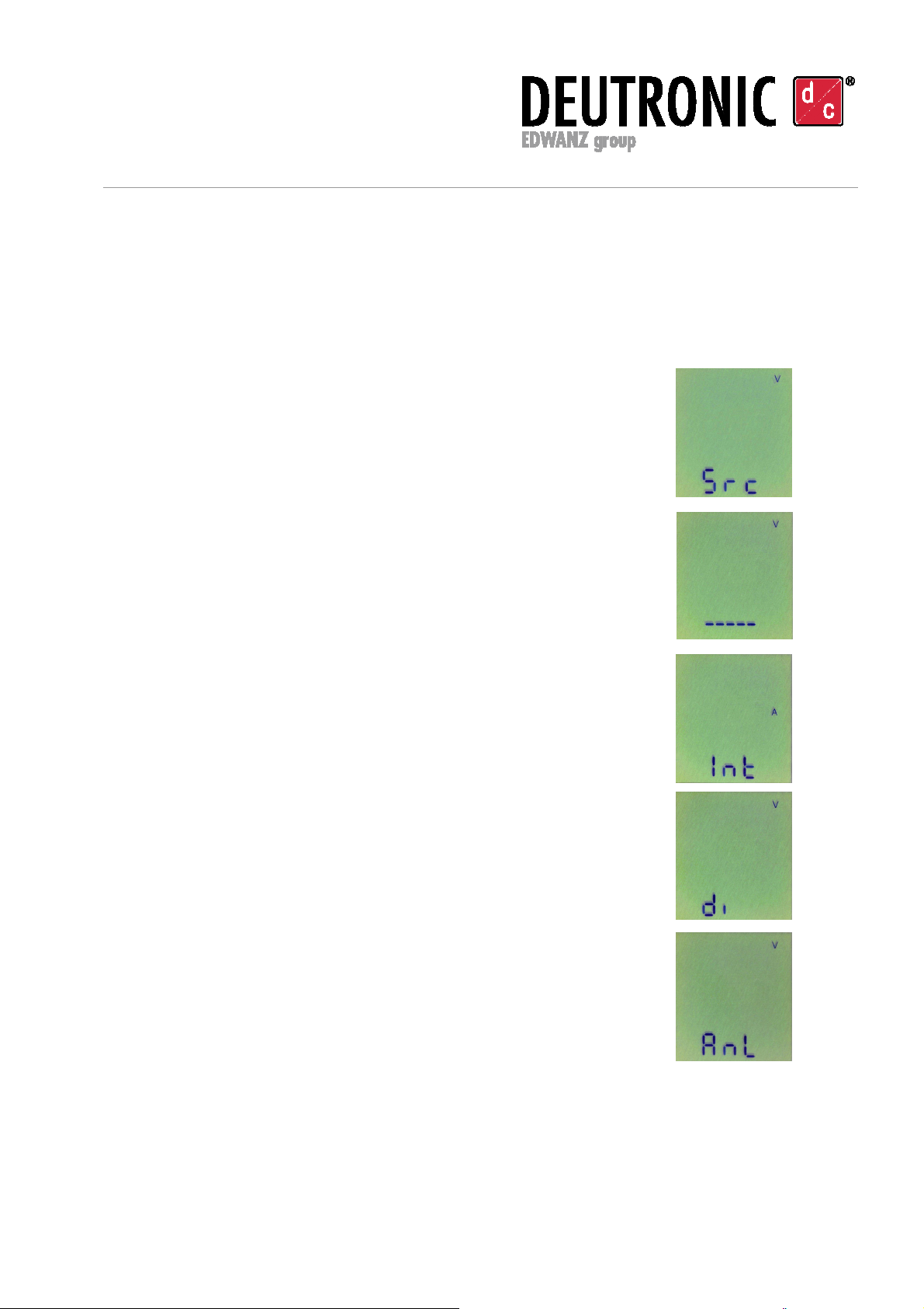
User interface / display:
At the top of the startdialogue the values for voltage and current as well as the selected
source (internal, analog, digital) are displayed.
Display: Current voltage value
at the output
Display: Actual current
at the output

Deutronic Elektronik GmbH
Deutronicstr. 5, D - 84166 Adlkofen
Tel.: +49 8707 920-0
Fax: +49 8707 1004
http://www.deutronic.com
Deutronic D-IPS Manual - EN Last updated: 07.12.2020 Page 7 of 20
D-IPS® und DEUTRONIC® sind eingetragene Marken der Deutronic Elektronik GmbH. Technische Änderungen und Irrtümer vorbehalten.
D-IPS® and DEUTRONIC® are registered trademarks of the Deutronic Elektronik GmbH. Technical modificationses and mistakes reserved.
®
Description of the display:
In the basic variant the device has following reference values –default options (data sources)
- for each of the output variables (current and voltage)
Src
Source
Int
Internal
Values can be entered
on the front panel by the buttons
Anl
Analog
Value is
trans
mi
tt
ed in analog kind
(
0
...
10VDC)
di
Digital
Data communication via
the RS232 interface
(or other optional
interface - e.g. ETH / USB etc.)
Description of the LED-display:
Green LED:
-Voltage lead : LED lights
-Current lead : LED blinks (frequency 1)
-Power lead: LED blinks (frequency 2)
Red LED:
-Error: LED blinks
-Option: customer specific programming of the red LED
-
Normally the LC-display shows the actual values of voltage and current and in
set mode each level or function.
Note:
The source for the reference value input must be set, so that each input will be activated. By
internal input (buttons) the entered values will be taken at the source intput firstly. The source
can be selected via communication protocol as well. The values of the digital interface (RS-
232/ETH etc.) take precedence over the internal or analog source.
Deutronic Elektronik GmbH
Deutronicstr. 5, D - 84166 Adlkofen
Tel.: +49 8707 920-0
Fax: +49 8707 1004
http://www.deutronic.com
Deutronic D-IPS Manual - EN Last updated: 07.12.2020 Page 8 of 20
D-IPS® und DEUTRONIC® sind eingetragene Marken der Deutronic Elektronik GmbH. Technische Änderungen und Irrtümer vorbehalten.
D-IPS® and DEUTRONIC® are registered trademarks of the Deutronic Elektronik GmbH. Technical modificationses and mistakes reserved.
®
6) Configuration of the source for output voltage and current
The output voltage and the output current can be adjusted by the following sources:
Internal input Buttons on the unit
Analog input 0...10V
Digital input RS232 (option: Ethernet etc.)
6. a) Source input for the voltage by buttons
Press „ENTER“
Select with the buttons „↑“ or „↓“ “ Src„ (V)
(in this menu item the data source for the target value of the
output voltage will be selected)
Press „ENTER“
There are three menu items to choose from:
Each source can be selected with the buttons „↓“ or „↑“
1. Selection „Internal Source“ for the voltage target value
2. Source selection „Digital Input“ (like RS232, Ethernet etc.)
3. Selection „Analog Input 0...10V“ for the voltage target value

Deutronic Elektronik GmbH
Deutronicstr. 5, D - 84166 Adlkofen
Tel.: +49 8707 920-0
Fax: +49 8707 1004
http://www.deutronic.com
Deutronic D-IPS Manual - EN Last updated: 07.12.2020 Page 9 of 20
D-IPS® und DEUTRONIC® sind eingetragene Marken der Deutronic Elektronik GmbH. Technische Änderungen und Irrtümer vorbehalten.
D-IPS® and DEUTRONIC® are registered trademarks of the Deutronic Elektronik GmbH. Technical modificationses and mistakes reserved.
®
After selecting the desired source it will take over when „ENTER“-button is pressed.
After a successful takeover of the source the display shows „Ok“.
When the display shows„no“ the source was not taken over and the selection must be
done once again.
Exit from this menu level with any button „Src“ (V).
Press the buttons „↓“ and „↑“ at the same time to get out of the menu level, without
overtaking the source. Press the buttons „↓“ and „↑“ simultaneous once again to get out of
the menu, then it shows the current values for current and voltage.
6. b) Source input for the current by buttons
Press „ENTER“
Select with the buttons „↑“ or „↓“ „Src“ (A)
(in this menu item the data source for the target value of the
output current will be selected)
Press „ENTER“
There are three menu items fo choose from:
Each source can be selected with the buttons „↓“ or „↑“
1. Selection „Internal Source“ for the current target value
2. Source selection „Digital Input“ (like RS232, Ethernet etc.)
3. Selection „Analog Input 0...10V“ for the current target value

Deutronic Elektronik GmbH
Deutronicstr. 5, D - 84166 Adlkofen
Tel.: +49 8707 920-0
Fax: +49 8707 1004
http://www.deutronic.com
Deutronic D-IPS Manual - EN Last updated: 07.12.2020 Page 10 of 20
D-IPS® und DEUTRONIC® sind eingetragene Marken der Deutronic Elektronik GmbH. Technische Änderungen und Irrtümer vorbehalten.
D-IPS® and DEUTRONIC® are registered trademarks of the Deutronic Elektronik GmbH. Technical modificationses and mistakes reserved.
®
After selecting the desired source it will take over when „ENTER“-button is pressed.
After a successful takeover of the source the display shows „Ok“.
When the display shows„no“ the source was not taken over and the selection must be
done once again.
Exit from this menu level with any button „Src“ (A).
Press the buttons „↓“ and „↑“ at the same time to get out of the menu level, without taking
over the source. Press the buttons „↓“ and „↑“ simultaneous once again to get out of the
menu, then it shows the current values for current and voltage
6. c) Buttons input of the reference values of the output sizes at internal
source
Following example shows the configuration of the reference values for the output voltage.
(Reference values for the output current will be adjusted in the same way).
Press button „ENTER“ for the first menu level.
The display shows the start symbol of the menu.
Choose with the buttons „↓“ or „↑“ the voltage target value „Int“ (V) in
this menu item.
Press „ENTER“ for the input of the voltage target value.
The changeable digit is marked with an underscore.
By pressing the button „↑“ or „↓“ the position can be changed.
With the button „ENTER“ the next digit is selected and so on.
After the desired target value has been set, it can be taken over.
This happens through simultaneous pressing of buttons „↓“ and „↑“ at
visible "OK" indicator
Exit with any button from this menu subitem to „Int“ (V).
At simultaneous pressing of buttons „↓“ and„↑“ while appears
no „Ok“ symbol, the in the meantime set parameter is not accepted.
In this case, all input steps must be repeated.
So the voltage reference value of the internal input is set.
The output voltage will be active to this value with the input of the source „Int“ (V) firstly.
To exit from this menu press „↓“ and „↑“to the same time.

Deutronic Elektronik GmbH
Deutronicstr. 5, D - 84166 Adlkofen
Tel.: +49 8707 920-0
Fax: +49 8707 1004
http://www.deutronic.com
Deutronic D-IPS Manual - EN Last updated: 07.12.2020 Page 11 of 20
D-IPS® und DEUTRONIC® sind eingetragene Marken der Deutronic Elektronik GmbH. Technische Änderungen und Irrtümer vorbehalten.
D-IPS® and DEUTRONIC® are registered trademarks of the Deutronic Elektronik GmbH. Technical modificationses and mistakes reserved.
®
7) Programming options (for OEM customers)
The following described device features and –functions can be programmed at Deutronic in
according to customer specification optionally and supplied as a customer specific variant
7. a) INPUT
Programmable input variables (OEM)
-maximum input current
-minimum activation voltage
-control of power consumption
-Inhibit/start release at phase loss (3AC only)
-Min./max. start release temperature
-Min./max. operating temperature
7. b) OUTPUT
Programmable output variables (OEM)
- Current limit / overload behavior
- Output characteristics- I-const., P-const., Hiccup, Fuse-Mode
- Overload behaviour
- Power reserve by time
- Operation control programmable (time–raster-control)
- Data recording
- Signalling freely programmable
- Exceeding of tolerance windows (U) with selectable delay time
- Early alert signal level: - Early warning
- Temperature – early shutdown signal
- too low Uin for required memory time
- Network Analysis
- Analog and digital inputs and outputs
The programming of the above described features can be realized in according to customer
specifications in our company.
Deutronic Elektronik GmbH
Deutronicstr. 5, D - 84166 Adlkofen
Tel.: +49 8707 920-0
Fax: +49 8707 1004
http://www.deutronic.com
Deutronic D-IPS Manual - EN Last updated: 07.12.2020 Page 12 of 20
D-IPS® und DEUTRONIC® sind eingetragene Marken der Deutronic Elektronik GmbH. Technische Änderungen und Irrtümer vorbehalten.
D-IPS® and DEUTRONIC® are registered trademarks of the Deutronic Elektronik GmbH. Technical modificationses and mistakes reserved.
®
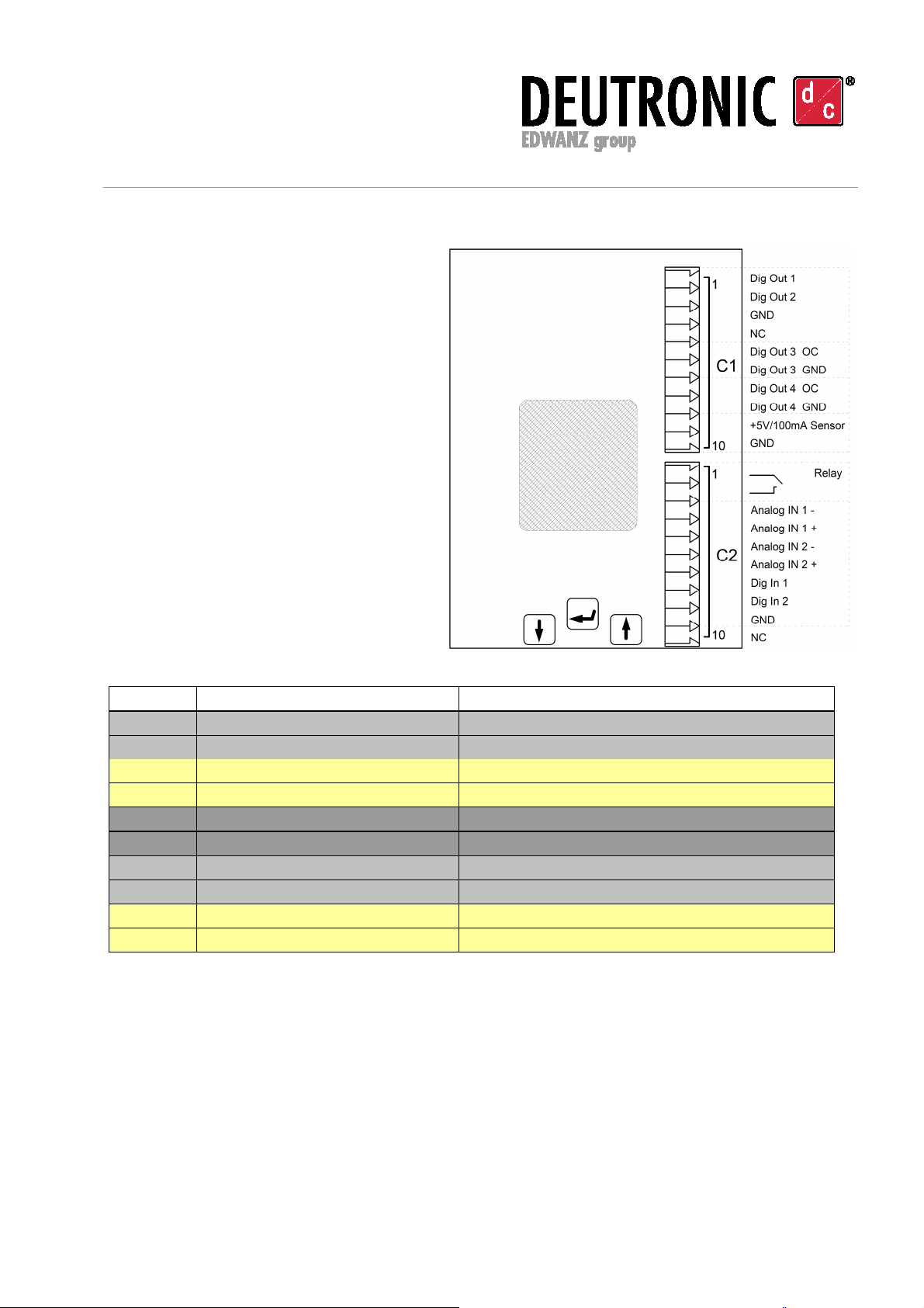
8) Input/Output-Interface
Digitally controlled secondary / Output
Connector C1: Status
PIN Configuration Function and level
1 DIGITAL-OUT-1 High, max. 20mA
2 DIGITAL-OUT-2 High, max. 20mA
3 GND
4 NC
5 DIGITAL-OUT-3 OC*, max. 50mA
6 DIGITAL-OUT-3 GND
7 DIGITAL-OUT-4 OC*, max. 50mA
8 DIGITAL-OUT-4 GND
9 +5VDC / 100mA Auxiliary voltage, floating (for active sensors)
10 GND (AUX)
Deutronic Elektronik GmbH
Deutronicstr. 5, D - 84166 Adlkofen
Tel.: +49 8707 920-0
Fax: +49 8707 1004
http://www.deutronic.com
Deutronic D-IPS Manual - EN Last updated: 07.12.2020 Page 13 of 20
D-IPS® und DEUTRONIC® sind eingetragene Marken der Deutronic Elektronik GmbH. Technische Änderungen und Irrtümer vorbehalten.
D-IPS® and DEUTRONIC® are registered trademarks of the Deutronic Elektronik GmbH. Technical modificationses and mistakes reserved.
®
Connector C2: Control / Sensing
PIN Configuration Function and level
1 Relay1 1-2 Make contact
2 Relay1
3
-ANALOG-IN-1
Spannung/Voltage
4
+ANALOG-IN-1
Spannung/Voltage 0..10VDC Control voltage
5 -ANALOG-IN-2 Strom/Current
6 +ANALOG-IN-2 Strom/Current 0..10VDC Control voltage
7 DIGITAL-IN-1 0 / 5VDC Level
8 DIGITAL-IN-2 0 / 5VDC Level
9 GND
10 NC
*OC = Open Collector
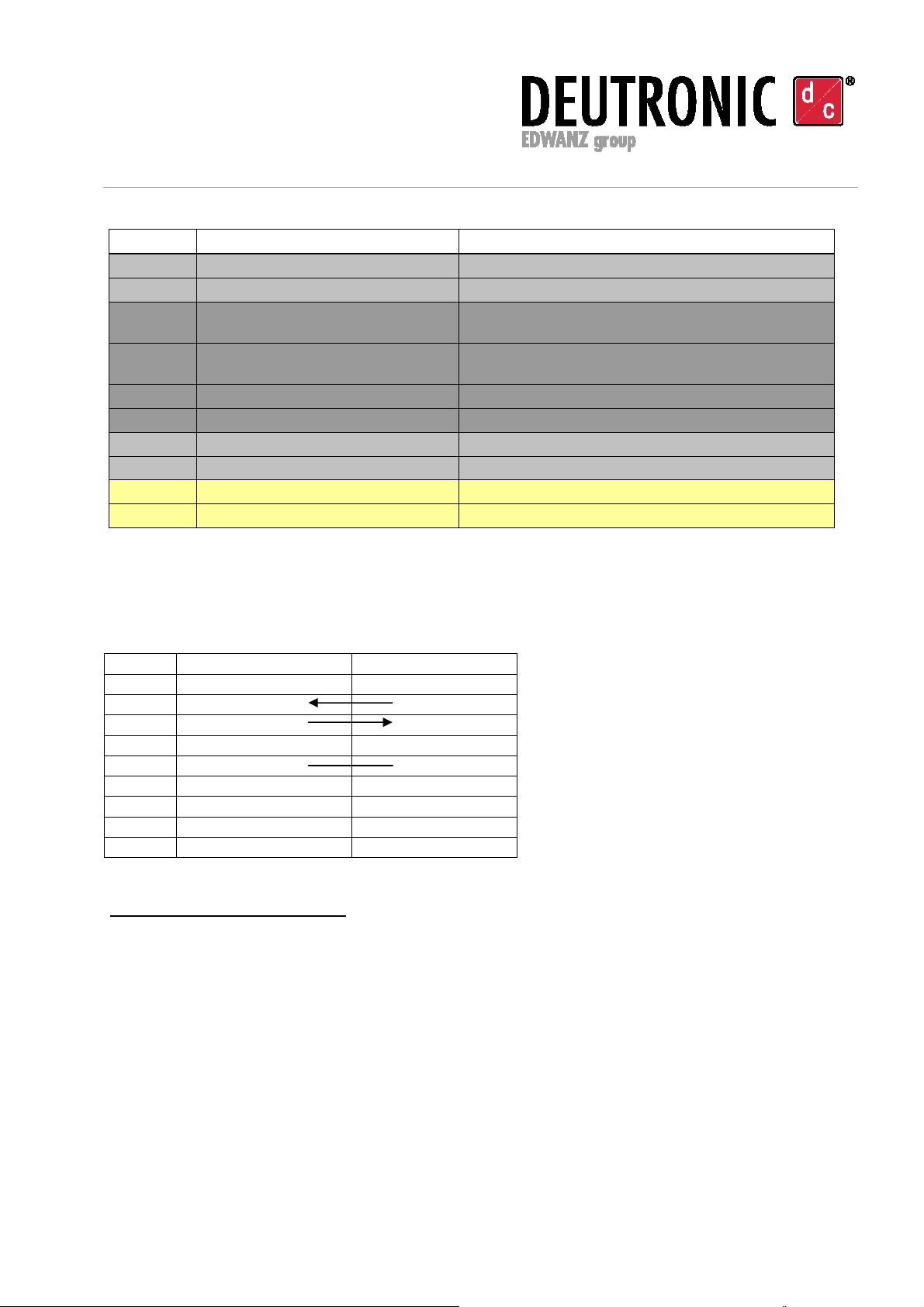
9) Communication via RS-232 or Ethernet
9. a) The RS232-interface:
Pin No.
Control
-
PC
AC/DC
-
Source
1 DCD not used
2
RxD
TxD
3
TxD
RxD
4 DTR not used
5
GND
GND
6 DSR not used
7 RTS not used
8 CTS not used
9 RI Not used
RS-232 Interface parameters:
Baudrate: 57600 baud
Datenbits: 8
Parity: none
Stopbit: 1
Handshake: none
Protokoll: <STX>/<ETX> (further details are described below)
9. b) The Ethernet-Interface (order option):
The Ethernet-Interface is used to connect the controllable power supply of D-IPS
®
-C series
to a 10/100Mbit Ethernet (TCP/IP or UDP).
Deutronic Elektronik GmbH
Deutronicstr. 5, D - 84166 Adlkofen
Tel.: +49 8707 920-0
Fax: +49 8707 1004
http://www.deutronic.com
Deutronic D-IPS Manual - EN Last updated: 07.12.2020 Page 14 of 20
D-IPS® und DEUTRONIC® sind eingetragene Marken der Deutronic Elektronik GmbH. Technische Änderungen und Irrtümer vorbehalten.
D-IPS® and DEUTRONIC® are registered trademarks of the Deutronic Elektronik GmbH. Technical modificationses and mistakes reserved.
®
®
Network-connection RJ45
Transmission standard Ethernet, IEEE 802.3
Protocols (supported) TCP/IP, UDP
Data rate max. 10 / 100 Mbps (Auto-Sensing)
For further information about Ethernet communication with the D-IPS
®
controllable power
supplies please contact our sales department.
10) Command structure – description of communication:
With various commands the D-IPS -C can be controlled remotely and configured via the
interface. Furthermore measured values can be requested in this way. The commands
themselves consist of printable ASCII-characters Also some non-printable control characters
are used for the control of data transmission.
Control characters
Value
Start character <STX> 0x02
End character <ETX> 0x03
Command mode
Extension
Example
Read Command
(R)
? OUT:UOUTS? request voltage reference
value
Write Command
(W)
,parameter OUT:UOUTS,10.0 set voltage reference value
to 10,0V
Example: <STX>OUT:UOUTS?<ETX>
Used shortcuts :
<STX> „Start of Text“ (ASCII-Code 2)
will sent before start of a command
<ETX> „End of Text“ (ASCII-Code 3)
will sent after the end of a command
<ACK> „Acknowledge“ (ASCII-Code 6)
Response, when control command has been processed successfully
<NAK> „Negative Acknowledge“ (ASCII-Code 21)
Response, when control command can not be performed
<ERR> Error (ASCII-Code 7)
Response, when control command is unknown
<Z> Zahl / Number with decimal point and a decimal place e.g. 12.3 or 012.3

Deutronic Elektronik GmbH
Deutronicstr. 5, D - 84166 Adlkofen
Tel.: +49 8707 920-0
Fax: +49 8707 1004
http://www.deutronic.com
Deutronic D-IPS Manual - EN Last updated: 07.12.2020 Page 15 of 20
D-IPS® und DEUTRONIC® sind eingetragene Marken der Deutronic Elektronik GmbH. Technische Änderungen und Irrtümer vorbehalten.
D-IPS® and DEUTRONIC® are registered trademarks of the Deutronic Elektronik GmbH. Technical modificationses and mistakes reserved.
®
Command structure:
Control commands and replies are transferred in the form of ASCII-character chains.
It is used as start character the <STX> - as last character <ETX>
A distinction is made between uppercase and lowercase.
The control commands are processed in the order, in which they were received.
Each command consists of a main group command and one or two sub-group command,
these are connected with „ : “. Then the marking of the type of the command follows.
The possible commands are divided into three types. READ, WRITE, EXECUTE. The
differentiation is made by the appropriate sign after the main command.
READ ?
WRITE ,
EXECUTE no sign
At the WRITE-commands for the input of voltage, current and power a number input with one
decimal place must be done after the WRITE-character „ , “. The decimal places in decimal
numbers are separated with „ . “.
Example for control commands:
<STX>OUT:UOUTS?<ETX>
This command is a READ-command. The output voltage is requested.
<STX>OUT:UOUTS,24.0<ETX>
This command is a WRITE-command. The output voltage is set to 24,0V.
<STX>PER:DIG1:ON<ETX>
This command is a EXECUTE-command. The digital output 1 is set to HI-level.
Commands are answered either with <ACK>, <NAK> or with <ERR>.

Deutronic Elektronik GmbH
Deutronicstr. 5, D - 84166 Adlkofen
Tel.: +49 8707 920-0
Fax: +49 8707 1004
http://www.deutronic.com
Deutronic D-IPS Manual - EN Last updated: 07.12.2020 Page 16 of 20
D-IPS® und DEUTRONIC® sind eingetragene Marken der Deutronic Elektronik GmbH. Technische Änderungen und Irrtümer vorbehalten.
D-IPS® and DEUTRONIC® are registered trademarks of the Deutronic Elektronik GmbH. Technical modificationses and mistakes reserved.
®
®
Command list of D-IPS - C series 250W, 350W, 500W:
Running system commands:
DEV:GO
Description: Power module will be activated
Return value: <ACK>
DEV:STOP
Description: Power module will be switched off
Return value: <ACK>
Output control:
OUT:UOUT?
Description: Measurement of current voltage at the output
Return value: <Z>
OUT:UOUTS?
Description: Measurement of nominal voltage for output
Return value: <Z>
OUT:IOUT?
Description: Measurement of actual current at the output
Return value: <Z>
OUT:IOUTS?
Description: Measurement of nominal current for output
Return value: <Z>
OUT:UOUTS,x
Description: Setting of nominal value for output voltage
Parameter: x= 0.0 to max. value e.g. 24.0 [V] (system-specific)
Return value: <ACK> / <NAK>
Basic setting: 0.0
OUT:IOUTS,x
Description: Setting of nominal value for output current
Parameter: x= 0.0 to max. value e.g. 20.0 [A] (system-specific)
Return value: <ACK> / <NAK>
Basic setting: 0.0

Deutronic Elektronik GmbH
Deutronicstr. 5, D - 84166 Adlkofen
Tel.: +49 8707 920-0
Fax: +49 8707 1004
http://www.deutronic.com
Deutronic D-IPS Manual - EN Last updated: 07.12.2020 Page 17 of 20
D-IPS® und DEUTRONIC® sind eingetragene Marken der Deutronic Elektronik GmbH. Technische Änderungen und Irrtümer vorbehalten.
D-IPS® and DEUTRONIC® are registered trademarks of the Deutronic Elektronik GmbH. Technical modificationses and mistakes reserved.
®
Source changes of nominal value for voltage and current:
Voltage source:
SORV:INT
Description: Switching to the internal input of nominal value for voltage
(entered value by buttons on the display)
Return value: <ACK>
SORV:DIG
Description: Switching to the digital input of nominal value for voltage
(RS232 interface)
Return value: <ACK>
SORV:ANL
Description: Switching to the analog input of nominal value for voltage
(analog input 0...10V)
Return value: <ACK>
Current source:
SORA:INT
Description: Switching to the internal input of nominal value for current
(entered value by buttons on the display)
Return value: <ACK>
SORA:DIG
Description: Switching to the digital input of nominal value for current
(RS232 interface)
Return value: <ACK>
SORA:ANL
Description: Switching to the analog input of nominal value for current
(analog input 0...10V)
Return value: <ACK>

Deutronic Elektronik GmbH
Deutronicstr. 5, D - 84166 Adlkofen
Tel.: +49 8707 920-0
Fax: +49 8707 1004
http://www.deutronic.com
Deutronic D-IPS Manual - EN Last updated: 07.12.2020 Page 18 of 20
D-IPS® und DEUTRONIC® sind eingetragene Marken der Deutronic Elektronik GmbH. Technische Änderungen und Irrtümer vorbehalten.
D-IPS® and DEUTRONIC® are registered trademarks of the Deutronic Elektronik GmbH. Technical modificationses and mistakes reserved.
®
Periphery control:
PER:DIN1?
Description: State of digital input 1
Return value: „SET“ / „ CLEAR“
PER:DIN2?
Description: State of digital input 2
Return value „SET“ / „ CLEAR“
PER:DIG1:ON
Description: State of digital output 1
Subcommand: „ON“ / „OFF“
Return value <ACK>
Basic setting: „OFF“
PER:DIG2:ON
Description: State of digital output 2
Subcommand: „ON“ / „OFF“
Return value <ACK>
Basic setting: „OFF“
PER:DIG3:ON
Description: State of digital output 3
Subcommand: „ON“ / „OFF“
Return value <ACK>
Basic setting „OFF“
PER:DIG4:ON
Description: State of digital output 4
Subcommand „ON“ / „OFF“
Return value <ACK>
Basic setting: „OFF“
PER:REL1:ON
Description: State of relay output 1
Subcommand „ON“ / „OFF“
Return value: <ACK>
Basic setting: „OFF“

Deutronic Elektronik GmbH
Deutronicstr. 5, D - 84166 Adlkofen
Tel.: +49 8707 920-0
Fax: +49 8707 1004
http://www.deutronic.com
Deutronic D-IPS Manual - EN Last updated: 07.12.2020 Page 19 of 20
D-IPS® und DEUTRONIC® sind eingetragene Marken der Deutronic Elektronik GmbH. Technische Änderungen und Irrtümer vorbehalten.
D-IPS® and DEUTRONIC® are registered trademarks of the Deutronic Elektronik GmbH. Technical modificationses and mistakes reserved.
®
11) Notes

Deutronic Elektronik GmbH
Deutronicstr. 5, D - 84166 Adlkofen
Tel.: +49 8707 920-0
Fax: +49 8707 1004
http://www.deutronic.com
Deutronic D-IPS Manual - EN Last updated: 07.12.2020 Page 20 of 20
D-IPS® und DEUTRONIC® sind eingetragene Marken der Deutronic Elektronik GmbH. Technische Änderungen und Irrtümer vorbehalten.
D-IPS® and DEUTRONIC® are registered trademarks of the Deutronic Elektronik GmbH. Technical modificationses and mistakes reserved.
®
12) Annex - accessories
Software, mounting bracket, output clamps, RS232 adapter etc. can be found on our
webpage www.deutronic.com.
13) Service Center / Repair
Do not open this device!
All needed connections and setting elements for operation are accessible from outside.
Please pay attention to following instructions:
To ensure a fast and smooth processing it is absolutely important that every device sent to
Deutronic for repair has a full filled out return service scripture in which for every device all
relevant data (e.g. address, name contact person, phone number etc.) as well as a detailed
fault description is included.
The needed return service scripture as well as the world wide service partner addresses you
will find on our webpage www.deutronic.com in the menu item 'service worldwide'.
Disclaimer:
The customer is responsible for the use of the device according to the specifications.
Regardless of the type, Deutronic is not liable for damage incurred through the use of the
device.
Contact:
Deutronic Elektronik GmbH
Deutronicstrasse 5
84166 Adlkofen / Germany
Tel.: +49 8707 920-0
Fax: +49 8707 1004
E-Mail: sales@deutronic.com
http://www.deutronic.com
DC Nr.
33619
All data at nominal input, full load and 25
°
C ambient temperature, if not marked otherwise.
Technical modifications and mistakes reserved.
Products are described by information contained in catalogs and data-sheets. It is not be considered as
assured qualities. Stresses listed under „Maximum Rating“ (one at a time) may be applied to devices without
resulting in permanent damage. The operation of the equipment for extended periods may affect device reliability.
Limiting value tolerance are subject to usual fluctuation.
This manual suits for next models
3
Table of contents


