K-BUS KP/D 30.640.1 User manual

K-BUS®Power Supply_V1.1
KP/D 30.640.1
KNX/EIB Home and Building Control System
User Manual

Attentions
1. Please keep devices away from strong magnetic field, high
temperature, wet environment;
2. Do not fall the device to the ground or make them get hard impact;
3. Do not use wet cloth or volatile reagent to wipe the device;
4. Do not disassemble the devices.

Contents
Chapter 1 Introduction----------------------------------------------------------------------------------------------------------------1
Chapter 2 Technical Parameter--------------------------------------------------------------------------------------------------- 2
Chapter 3 Dimension and Connection Diagram---------------------------------------------------------------------------- 3
3.1. Dimension drawing----------------------------------------------------------------------------------------------------------- 3
3.2. Connection Diagram--------------------------------------------------------------------------------------------------------- 4
Chapter 4 Normal Working Test---------------------------------------------------------------------------------------------------4

Important safeguards
1) Before use, please read this instruction carefully and use the power supply strictly according to
the instruction.
2) This power supply is for indoor use only and shall be installed in distribution box which can
provide the protection mechanism for avoid electric shock.
3) Please keep this equipment from humidity.
4) Before use, the input and output voltage must be checked to secure correct use.
5) The cover may under no circumstances be opened. If the cover is damaged, then the adaptor
may no longer be used.
6) The power supply shall be installed and used according to national wiring rules.
7) For indoor use only.
8) The product is not a toy, keep it where the children can not reach it.
9) The power supply are only supply for EIB / KNX system equipment with bus line connection
terminal.
10) Correct Disposal of this product:
This marking indicates that this product should not be disposed with other household wastes
throughout the EU. To prevent possible harm to the environment or human health from uncontrolled
waste disposal, recycle it responsibly to promote the sustainable reuse of material resources. To return
your used device, please use the return and collection systems or contact the retailer where the product
was purchased. They can take this product for environmental safe recycling.

K-BUS®KNX/EIB Power Supply
1
Chapter 1 Introduction
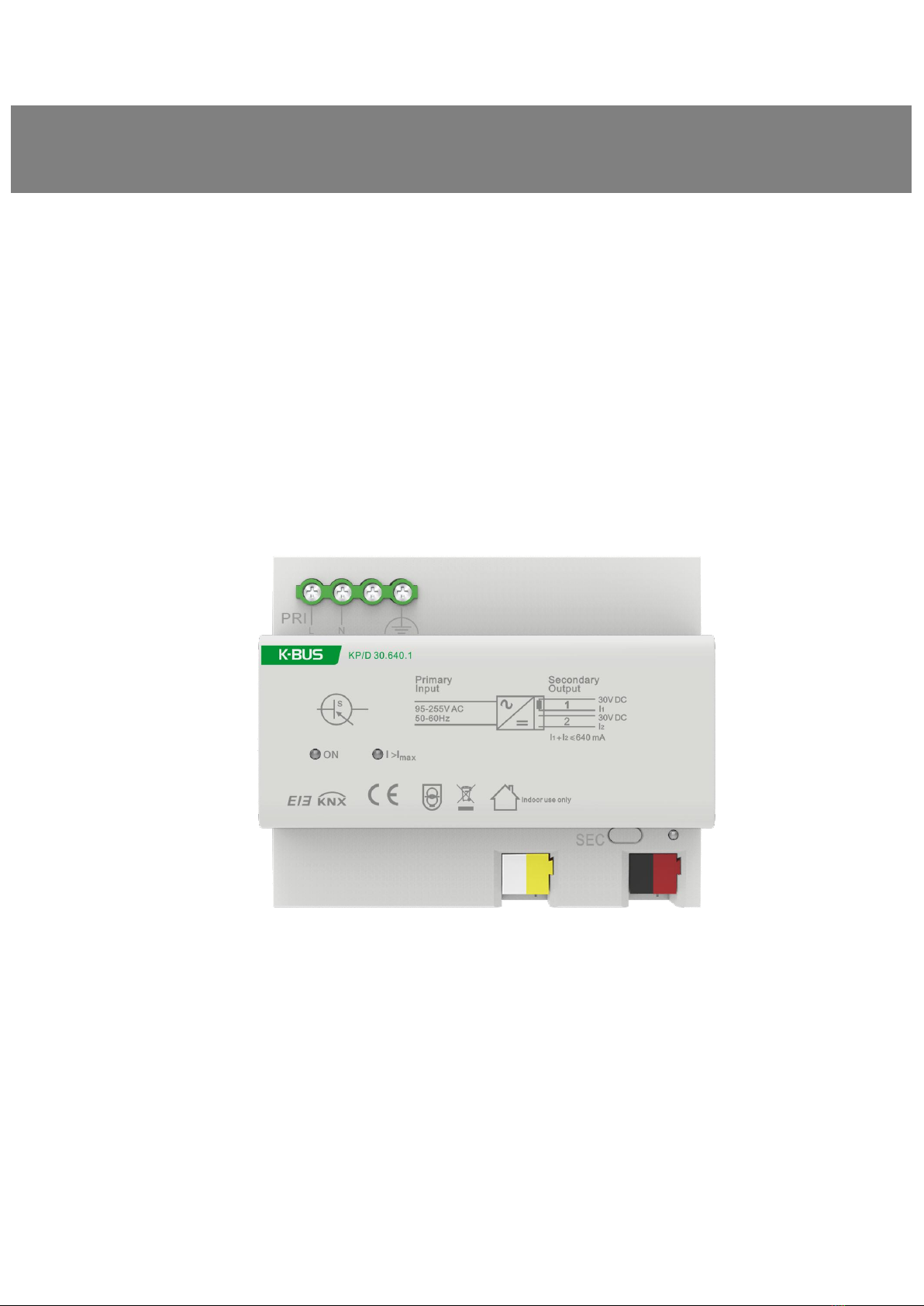
KNX power supply produces and monitors KNX system voltage. There are two connection
terminal of the output, one for KNX bus supply and signal transmission, one for auxiliary power
supply, can provide 30V DC voltage with terminal device.The bus connection terminal has
integrated the reactor inside the power supply; if the auxiliary power supply terminal is connected
with an external reactor, it can also be used as the bus power supply terminal, and also with the
function of signal transmission.
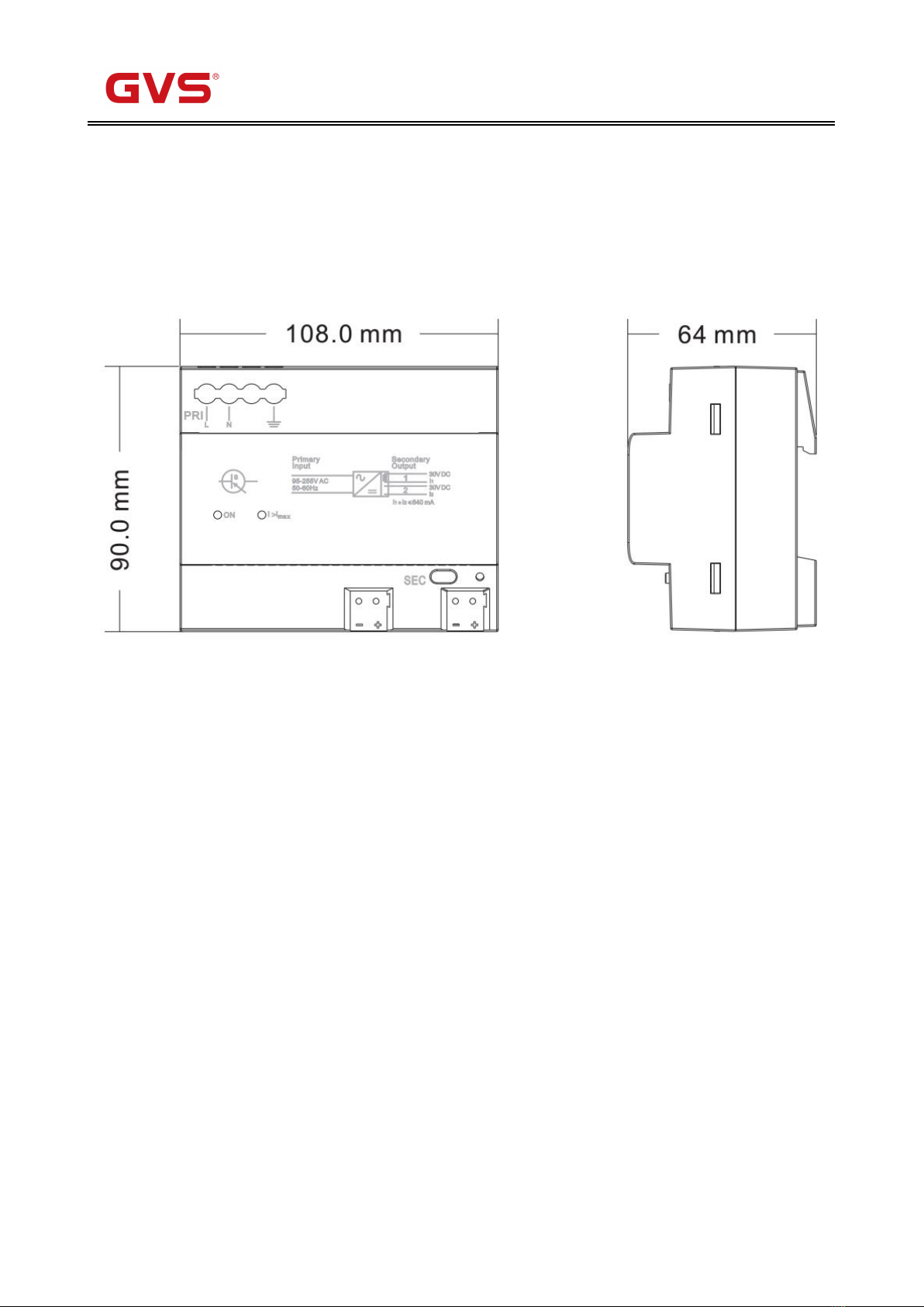
The KNX power supply is an analog-to-digital installation equipment. In order to facilitate the
installation in the distribution box, according to the design of EN 60715, it can be installed on a
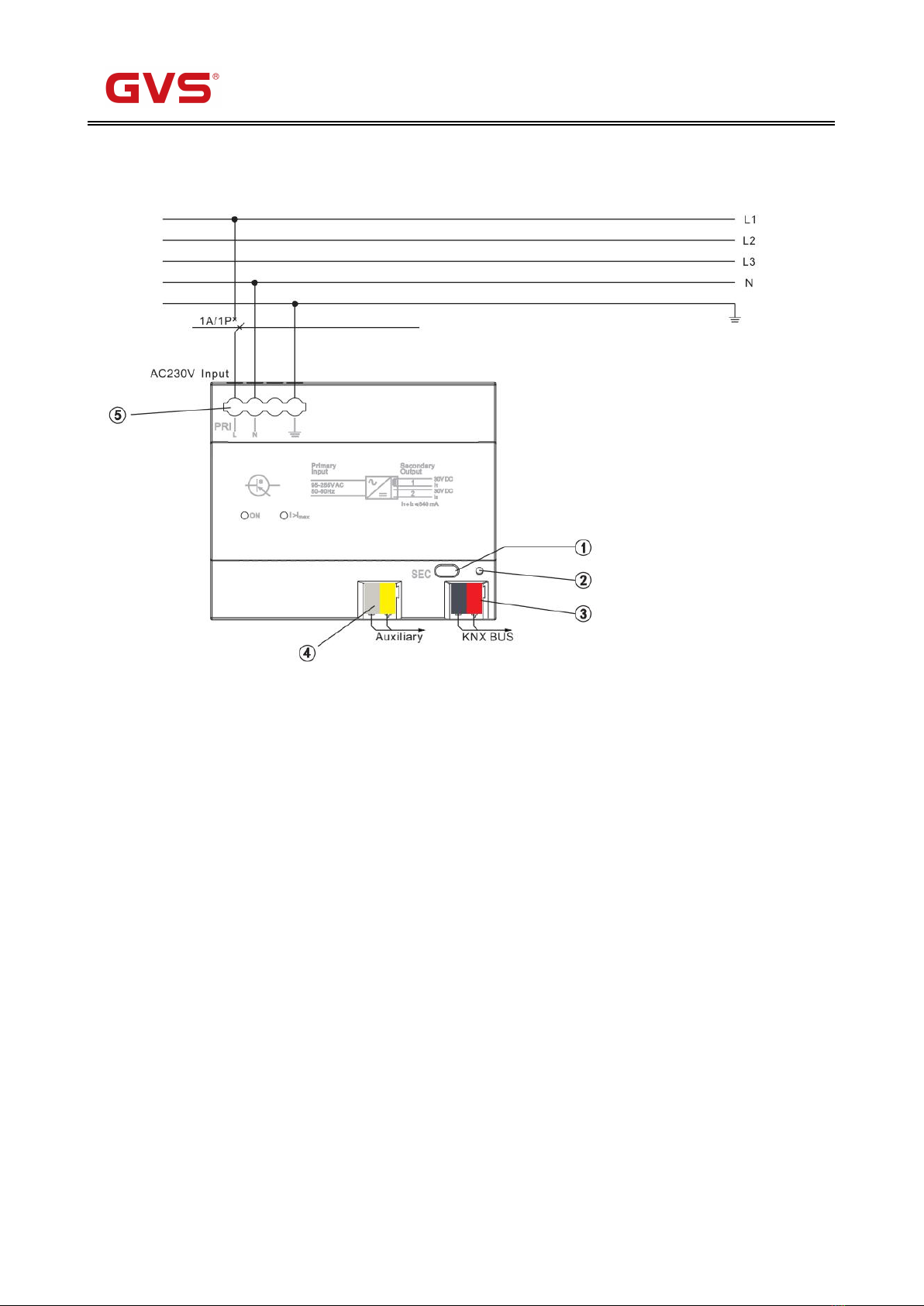
35mm DIN rail. The device is connected with the screw post for electrical connection. The bus
connection is directly connected through the KNX connection terminal (red/ black). The auxiliary
power supply is also connected directly through the KNX connection terminal (yellow/ white), and
the input end is connected to the power supply voltage of 230V AC.
A reset of the power supply is triggered by pressing the reset button last for 22 seconds
(regardless of the duration of the button action).When bus supply terminal is disconnected from the
power supply,other devices on the bus will return to their initial state. If bus disconnect for a longer
period, the bus supply terminal must be removed from power supply.

K-BUS®KNX/EIB Power Supply
2
Chapter 2 Technical Parameter
Power supply
Input voltage
95V ~255 V AC,50/60Hz
Power loss
<6 W
Efficiency
75%
Output
KNX output (DPSU)
1 fold with integrated choke
KNX nominal voltage
30 V DC +1/–2 V, SELV
Auxiliary voltage output
1 (without choke)
Auxiliary voltage
30 V DC +1/–1 V, SELV
KNX nominal current
(Total of KNX and auxiliary voltage output)
640 mA, short-circuit-proof
Sustained short-circuit current
< 1.3 A
Mains failure back-up time
>200ms
Operating and
display
Green LED “ON”
Output voltage is OK
Red LED “I>Imax”
Overload or short circuit
Reset button(SEC)
Reset at the KNX output (starts when the push
button is pressed and lasts 22 seconds);
Red LED
Reset at the KNX output.
Connection
Power supply
2-srew terminals
Cable cross-section
Single-core 0.2—4.0mm2
Multi-core 0.2—2.5mm2
KNX output
Bus connection terminal (red/black)
Auxiliary voltage output
Connection terminal (yellow/white)
Protection
IP 20, EN 60529
Temperature
Operation
-5 °C ~ + 45 °C
Storage
– 25 °C ~ + 55 °C
Transport
– 25 °C ~ + 70 °C
Housing, Color
Plastic, Beige
Mounting
On 35mm mounting rail
Dimension
90mm×108mm×64mm
Weight
0.2kg
CE norm
In accordance with the EMC guideline and the low voltage guideline

K-BUS®KNX/EIB Power Supply
3
Chapter 3 Dimension and Connection Diagram
3.1. Dimension drawing

K-BUS®KNX/EIB Power Supply
4
3.2. Connection Diagram
1. Reset push button
2. Red LED (Reset)
3. Bus connection terminal (KNX output)
4. Connection terminal (auxiliary voltage output)
5. Mains supply
ON: Green LED(output voltage is OK)
I>Imax: Red LED(overload/ short circuit)
Chapter 4 Normal Working Test
When power supply has been correctly installed, switch on the main power supply for the bus
power,and the green LED “ON”, all other LEDs are switched off, that is, the device function correctly.
Table of contents
Other K-BUS Power Supply manuals