4
Note: 1. The fan is one of the replacement parts.
2. As defined with the rated input voltage and rated output voltage/current.
3. A surge absorber is provided for the input circuits of 300 and 600-W models. To test the dielectric strength and insulation resis-
tance of these models, remove the short bar attached across the GR and ACG terminals.
4. To ensure emission enclosure rating, ferrite cores should be used on all cabling on 300/600 models.
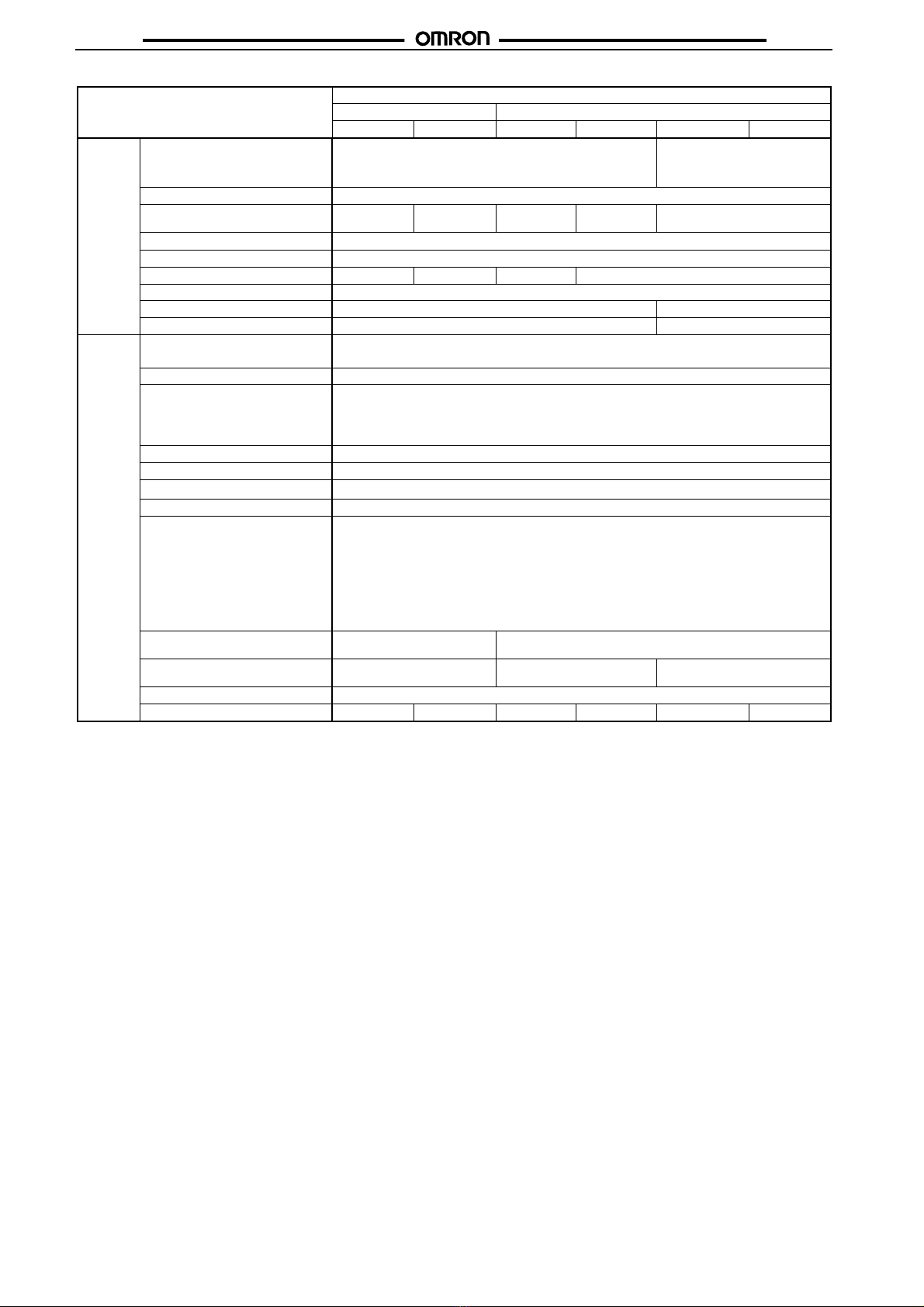
Item PFC
No Yes
100 W 150 W 100 W 150 W 300 W 600 W
Addition-
al func-
tion
Overload protection 105% max. of rated load current, inverted L drop type, automatic
reset
105% max. of rated load current,
inverted L drop type, automatic re-
set (output shut off after 5 s, reset
by input reset)
Overvoltage protection 120% of rated output voltage (typical), shutoff type, input reset
Parallel operation No Yes, 5 Units
max.
No Yes, 5 Units
max.
Yes, 2 Units max.
Series operation Yes
Remote sensing Yes
Remote control No Yes No Yes
Remote voltage adjustment Yes
Cooling method Natural air-cooling used Forced air-cooling with built-in fan
Fan alarm function No Yes
Other Ambient temperature Operating: See the derating curve in the “Engineering Data” section. No condensation or icing.
Storage: –25°C to 65°C with no condensation or icing
Ambient humidity (operating) 25% to 85%
Dielectric strength 3 kVAC, 50/60 Hz for 1 min between all inputs and all outputs with a current leakage of 25 mA max.
2.5 kVAC, 50/60 Hz for 1 min between all inputs and GR terminals with a current leakage of 25 mA max.
1.0 kVAC, 50/50 Hz for 1 min between all outputs and GR terminals with a current leakage of 15 mA
max. for each 100-W model, 20 mA max. for each 150-W model, 25 mA max. for each 300-W model,
and 50 mA max. for each 600-W model. (See note 3.)
Insulation resistance 100 MΩmin. between all outputs and all inputs/GR terminals at 500 VDC (See note 3.)
Vibration resistance Malfunction: 10 to 55 Hz, 0.375-mm single amplitude for 2 hrs each in X, Y, and Z directions
Shock resistance Malfunction: 300 m/s2(approx. 30G), 3 times each in ±X, ±Y, and ±Z directions
Output indicator Yes (green)
EMC Emission Enclosure: EN55011 Group 1 class A (PFC models)
EN55022 Group 1 class B (Non-PFC models)
Emission AC Mains: EN55011 Group 1 class A (PFC models)
EN55022 Group 1 class B (Non-PFC models)
Immunity ESD: EN61000-4-2: 4 kV contact discharge (level 2)
8 kV air discharge (level 3)
Immunity RF-interference: ENV50140: 10 V/m (10 k to 1 GHz) (level 3)
Immunity Conducted Disturbance: ENV50141: 10 V (0.15 to 80 MHz) (level 3)
Immunity Burst: EN61000-4-4: 2 kV power-line (level 3)
2 kV I/O signal-line (level 4)
Limits for harmonic current emis-
sion
--- Conforms to EN61000-3-2, IEC1000-3-2
EMC standards Conforms to EN50081-1,
EN50082-2
Conforms to EN50081-2,
EN50082-2
Conforms to EN50081-2,
EN50082-2 (See note 4.)
Approved standards UL1012, CSA E.B. 1402C, VDE 0160, IEC 950, EN 60950
Weight 950 g max. 1,800 g max. 1,050 g max. 1,850 g max. 3,500 g max. 5,500 g max.