EECI AR-1 Use and care manual

TABLE OF CONTENTS
Specifications....................................... page 1
Technical Support and Warranty.......... page 1
Connection Diagram............................. page 2
Power Supply Requirements................. page 2
RS-232 Connector Pin-outs.................. pages 2 & 3
Set-up and Testing............................... page 3
Mounting............................................... page 3
Troubleshooting................................... page 4
Control Software................................... page 4
Programming Examples......................... page 5 & 6
Connection to a Gate Relay or Alarm.... page 6
SPECIFICATIONS
Power Supply....................... 12 volts DC (100ma)
Relays.................................. 2 (1 relay with the AR-1)
Relay Contacts..................... SPDT
Contact Rating (AC)............. 16 amp 250 VAC (12 amp with the AR-1)
Contact Rating (DC)............. 16 amp 30 VDC (12 amp with the AR-1)
Contact Rating (tungsten).... TV-5 120 VAC
Contact Rating (horsepower) 1/2 HP 120 VAC or 1 HP 240 VAC
Weight................................. 4 ounces
Size...................................... 2.375 inches by 3 inches (AR-1: 1.375" by 3")
DESCRIPTION
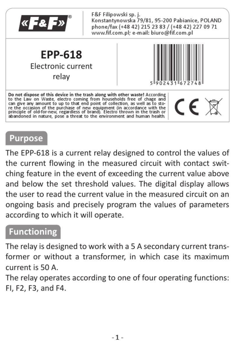
The AR-2 relay interface provides software control of (2) relays which are included and mounted on the AR-2 circuit
assembly. The relays are energized or de-energized by using the RS-232 control signals DTR and RTS. The AR-2
relay interface is useful when only 1 or 2 relays are required. The AR-2 is for use with RS-232 and is not expandable.
A terminal block is provided for connection of the power supply and relay contacts. RS-232 connections are made
via a DB-9 connector which is pin to pin compatible with the standard RS-232 nine pin connector.
TECHNICAL SUPPORT
Technical support for our products is available by calling (937) 349-6000. Please have your AR-2 connected to your
computer and have your phone at this location. If a technical adviser is not available, please leave your name, phone
number and a time that you can be reached. Your call will be returned as soon as possible and within 8 hours.
WARRANTY AND CARE OF THE AR-2
The AR-2 Relay Interface is warranted against factory defects for a period of 90 days from the date of purchase. The
AR-2 has proven to be extremely reliable in actual operation during field tests. We recommend that the AR-2 and
associated hardware be installed in a suitable enclosure (4 mounting holes are provided on the circuit board).
Page 1
TECHNICAL REFERENCE
AR-1 AR-2
RELAY INTERFACE
Click for more info: www.eeci.com/ar-2p.htm
(937) 349-6000
(800) 842-7714
(937) 349-6000
PHONE...................
ORDERS................
TECH SUPPORT...
E-mail.....................
www.eeci.com

NOTE: The DB-9 and DB-25 connector pin-outs shown on the preceding page are viewed from the solder side of the
connector. The illustration shown is that of a socket (female connector). The pin assignments for a plug (male
connector) will be the same but the illustration will appear backwards.
CONNECTING TO A 9 PIN RS-232 CONNECTOR: The AR-2 Relay Interface may be plugged directly into a serial
port which uses a 9 pin RS-232 connector if space allows. You may prefer to connect the AR-2 to your serial port
using a short cable (for the sake of neatness or more practical mounting). When using a cable to connect the AR-2 to
your serial port, only 3 of the nine pins are used. Connect pins #4, #5 and #7 on your 9 pin serial port to the
corresponding pins on the AR-2 connector.
CONNECTING TO A 25 PIN RS-232 CONNECTOR: Connect the nine pin AR-2 connector to a 25 pin RS-232
connector as follows (only 3 of the 25 pins are used):
AR-2 connector (DB-9) to 25 pin RS-232 socket (DB-25)
pin #4 goes to pin #20 (not used with the AR-1)
pin #5 goes to pin #7
pin #7 goes to pin #4
SET-UP AND TESTING
Upon receiving your AR-2, you should connect and test the operation of the hardware to verify proper operation.
Please set-up and test the AR-2 as follows (IBM and Compatibles):
(1) Plug the serial cable into COM 1 of your computer and plug the other end into the DB-9 connector on the AR-2. If
you did not order a serial cable, a cable may be fabricated by soldering the wires to the proper connector as shown
above. Use caution not to set the AR-2 on a metal surface or damage could result.
(2) Connect the power supply to the AR-2 at the termianl block. Be sure to observe the (+) and (-) connections on the
AR-2 (reversed polarity may cause damage).
(3) Windows users should install the Windows test program provided on CD (Windows 95, 98, ME, 2000, XP and
Vista) Run setup.exe in the folder Windows Test Program (on CD supplied). If prompted about an older file, keep your
newer file. Once installed, run the AR-2 program. The program defaults to Com 1, other Com ports may be selected if
required. Click on the buttons to verify that each relay energizes one at a time and in the correct sequence (the relay
# should correspond with the relay # shown on the screen). If the relays do not energize, verify that you have the
correct voltage and polarity on terminals #1 and #2 on the AR-2 by using a voltmeter. Also check for the proper cable
Connections.
(4) If the operation of the relays is normal, than testing is now complete and the AR-2 may be placed in service.
MOUNTING OF THE AR-2
Four mounting holes are provided on the AR-2 for mounting to stand-off hardware and an enclosure. The MT-1
stand-off kit is available for this purpose.
Page 3
CONNECTION DIAGRAM
A R - 2 R E L A Y
I N T E R F A C E
NOTE: The terminal assignments are also shown on the AR-2 Relay Interface PCB. The RS-232
connections are made to the DB-9 connector on the AR-2 as shown on the following page.
The AR-1 will have just 5 terminals with the 6, 7 and 8 terminals shown above omitted.
POWER SUPPLY REQUIREMENTS
The AR-2 may be powered from any DC voltage source which will supply 100 ma within a voltage range of 9 to 14
volts. The recommend power supply for use with a single AR-2 Relay Interface is the PS-GP-1 wall transformer
supply. IMPORTANT: Use caution when connecting the power source, reversed polarity may cause damage. The AR-
2 may be ordered with the optional /T Transzorb and self-resetting fuse option. The heat dissipation of the relay coils
on the AR-2 will be greatly reduced with an unregulated 300 ma, 9 volt power source.
POWER SUPPLY FUSING: A 500 milliamp (.5 amp) in-line fuse should be installed in series with the (+) power
supply lead to protect the power supply and the AR-2 from damage (or you may use the /T option).
RS-232 CABLE CONNECTIONS & PIN-OUTS
Page 2
AR-2
SIDE
VIEW
3/4" Stand-Off
1/4" 4-40 Machine Bolt
1/4" 4-40 Machine Bolt
MP-A or MP-B
Mounting Panel
(1) Data Carrier Detect
(2) Received Data
(3) Transmitted Data
(4) Data Terminal Ready
(5) Signal Ground
(6) Data Set Ready
(7) Request to Send
(8) Clear to Send
(20) Data Terminal Ready
(1) Equipment Ground
(2) Transmitted Data
(3) Received Data
(4) Request to Send
(5) Clear to Send
(6) Data Set Ready
(7) Signal Ground
(8) Data Carrier Detect
RELAY #1
RELAY #2
(1) 12 Volt DC Power Supply (-) Black
(2) 12 Volt DC Power Supply (+) Red
(3) Relay #1 Common Contact
(4) Relay #1 Normally Closed Contact
(5) Relay #1 Normally Open Contact
(6) Relay #2 Common Contact
(7) Relay #2 Normally Closed Contact
(8) Relay #2 Normally Open Contact
RS-232
DB-9

SOFTWARE EXAMPLE IN QUICKBASIC
10 CLS:KEY OFF
20 BYTE = &H3FC: 'COM 1 Set Com Port NOTE: Remove the apostrophe after the line number
30 'BYTE = &H2FC: 'COM 2 to enable the COM Port or add the apostrophe to
40 'BYTE = &H3EC: 'COM 3 disable the COM Port.
50 'BYTE = &H2EC: 'COM 4
60 PRINT" AR-2 RELAY INTERFACE TEST COM 1"
70 PRINT:PRINT"(1) De-energize relay #1"
80 PRINT"(2) Energize relay #1"
90 PRINT"(3) De-energize relay #2"
100 PRINT"(4) Energize relay #2"
110 PRINT "(5) Exit program"
120 PRINT:PRINT"Press key to test relay"
130 K$=INKEY$:IF K$="" THEN 130 :'Check for key pressed
140 IF K$="5" THEN CLS: END :' Exit program
150 A=VAL(K$) :' Convert string to a number
160 IF A<1 OR A>4 THEN 130
170 GOSUB 190 :'Go to subroutine to control relays
180 GOTO 130 :'Return to loop
190 X=INP (BYTE) :'Read modem control register
200 IF A=1 THEN X=X AND (NOT 2) :'Set bit 1 to zero
210 IF A=2 THEN X=X OR 2 :'Set bit 1 to one
220 IF A=3 THEN X=X AND (NOT 1) :'Set bit 0 to zero
230 IF A=4 THEN X=X OR 1 :'Set bit 0 to one
240 OUT BYTE,X :'Write to modem control register (set relays)
250 RETURN
MODEM CONTROL REGISTER I/O PORTS
COM 1 3FC (hex)
COM 2 2FC
COM 3 3EC
COM 4 2EC
Page 5
TROUBLESHOOTING
(1) Check for correct power and polarity to your AR-2 by using a multimeter to check the voltage at the AR-2
power terminals (the 2 small terminals on the lower right side of the AR-2, with the terminal block on the bottom).
Voltage should be between 9 volts and 14 volts DC and the polarity should have the negative on the far right terminal
(marked on the underside of the AR-2).
(2) Check your cable to the AR-2. The cable used to connect the AR-2 to a 9 pin RS-232 com port is the CC-
DE9SAR2 which is a direct pin to pin cable. Pins 4, 5 and 7 must be connected through the cable from the DB9 male
to the DB9 female connectors. You may use a multimeter set to ohms to check for continuity. The cable used to
connect the AR-2 to a USB port is the CO-USB cable. When using this cable, it may be necessary to remove the 2
connector nuts on each side of the AR-2 DB9 to plug in the CO-USB. It is also necessary to install the USB cable
driver (provided with the CO-USB).
(3) Run the Test Program supplied on CD with your AR-2. Install the AR-2 Test Program on your computer. The
universal App will run on all Windows computers (follow installations in the readme file). The .Net App will run on
Windows XP (service pack 3), Windows Vista, Windows 7, 8 and 8.1. When the test program is first started, enter the
com port that your AR-2 is connected to. When the program starts, test the relays. The test program will not start if it
is unable to find the com port entered. If the program will not start or if the relays do not operate, go to the next step.
(4) Check the Com Port used with the AR-2. Open device manager by clicking on the "Open Device Manager"
button on your installation CD (or by going to control panel). Click the small triangle (or +) to the left of Ports to
expand the Ports category, right click on the Com port that you have the AR-2 connected to and click properties.
Check the Com port status and verify that you have the test program set to this Com port and verify that you have the
AR-2 connected to this Com port.
If you are connecting the AR-2 to a USB port, the Com port entry must be "Prolific USB to Serial Comm Port". Right
click on this entry, click properties and open the Driver tab. Your USB Com driver must be Prolific version 3.4.62.293
or higher (dated 10/17/2013 or later). If your USB Com driver is not up to date, then right click the "Prolific USB to
Serial Comm Port" entry and click update driver. If you do not see a "Prolific USB to Serial Comm Port" entry then the
USB cable driver is not correctly installed. You may re-install the driver from the supplied CD or Windows Update. You
may verify that you have the AR-2 connected to this "Prolific USB to Serial Comm Port" entry by watching the entry
and unplugging the AR-2 USB cable from your computer. The entry should disappear and then re-appear when you
re-connect the USB cable to the AR-2.
Please contact EECI Support at (800) 842-7714 or (937) 349-6000 if you require additional assistance or have
questions.
CONTROL SOFTWARE
The relays on the AR-2 are controlled with RTS and DTR which are RS-232 control lines and are primarily used for
controlling a modem (RTS=request to send and DTR=data terminal ready). The number 1 relay is energized by
placing RTS high by setting bit 1 in the modem control register. The number 2 relay is energized by placing DTR high
by setting bit 0 in the modem control register. Software examples in G W Basic, QuickBasic, Visual Basic, Turbo C,
C#, Microsoft ASP and others are provided on the disk supplied with your order. The AR-2 may be used with any RS-
232 COM port on your PC (provided that you know the correct I/O port for the modem control register). Standard
modem control register I/O ports for COM 1 through COM 4 are shown in the Basic program on page 4.
NOTE: The AR-1 uses only the RTS control line (DTR is not used). The AR-1 may be ordered with the control line set
to DTR if required. You may also change the AR-1 setting by breaking the circuit track and manually soldering the
jumper to DTR (contact EECI support for assistance).
Page 4

SIMPLE SOFTWARE EXAMPLE IN C#
private void Form1_Load(object sender, EventArgs e)
{
serialPort1.PortName ="Com4";
serialPort1.Open();
}
private void button1_Click(object sender, EventArgs e)
{
serialPort1.RtsEnable = true;
}
private void button2_Click(object sender, EventArgs e)
{
serialPort1.RtsEnable = false;
}
private void button3_Click(object sender, EventArgs e)
{
serialPort1.DtrEnable = true;
}
private void button4_Click(object sender, EventArgs e)
{
serialPort1.DtrEnable = false;
}
The above example uses 4 buttons to energize or de-energize both relays.
Page 6
RELAY #1
RELAY #2
PS-GP-1
9VDC
(-)
(+)
(C)
(NO)
SOLENOID
RELAY #1
RELAY #2
PS-GP-1
9VDC
(-)
(+)
(C)
(NO) 9-12v
Alarm
(+)
(-)
CONNECTION TO A LOW VOLTAGE ALARM
CONNECTION TO A 24 VOLT AC GATE SOLENOID
24 VAC
POWER
SUPPLY
Alarm must not overload the
PS-GP-1 wall adapter
PHONE*.................
ORDERS................
TECH SUPPORT...
E-mail*....................
web*........................
*International & Domestic
(937) 349-6000
(800) 842-7714
(937) 349-6000
https://www.eeci.com
ELECTRONIC ENERGY CONTROL, INC.
14960 Maple Ridge Rd
Milford Center OH 43045-9016
USA
Copyright 1992 - 2020 Electronic Energy Control, Inc. All Rights Reserved
c
®
This manual suits for next models
1
