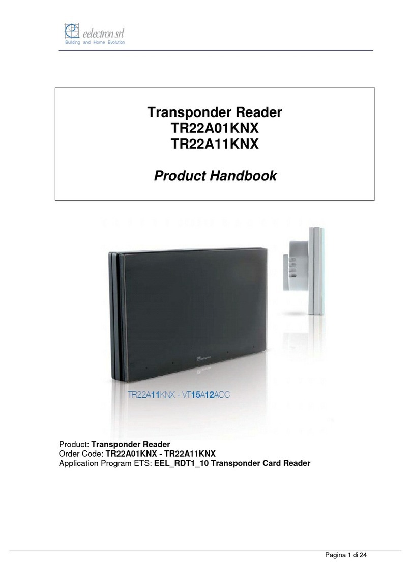
Eelectron TR22A01KNX User manual

TR22A01KNXFI04020001
Lettore Transponder
TR22A0xKNX –Grigio Chiaro
TR22A1xKNX –Antracite
TR22A2xKNX –Bianco
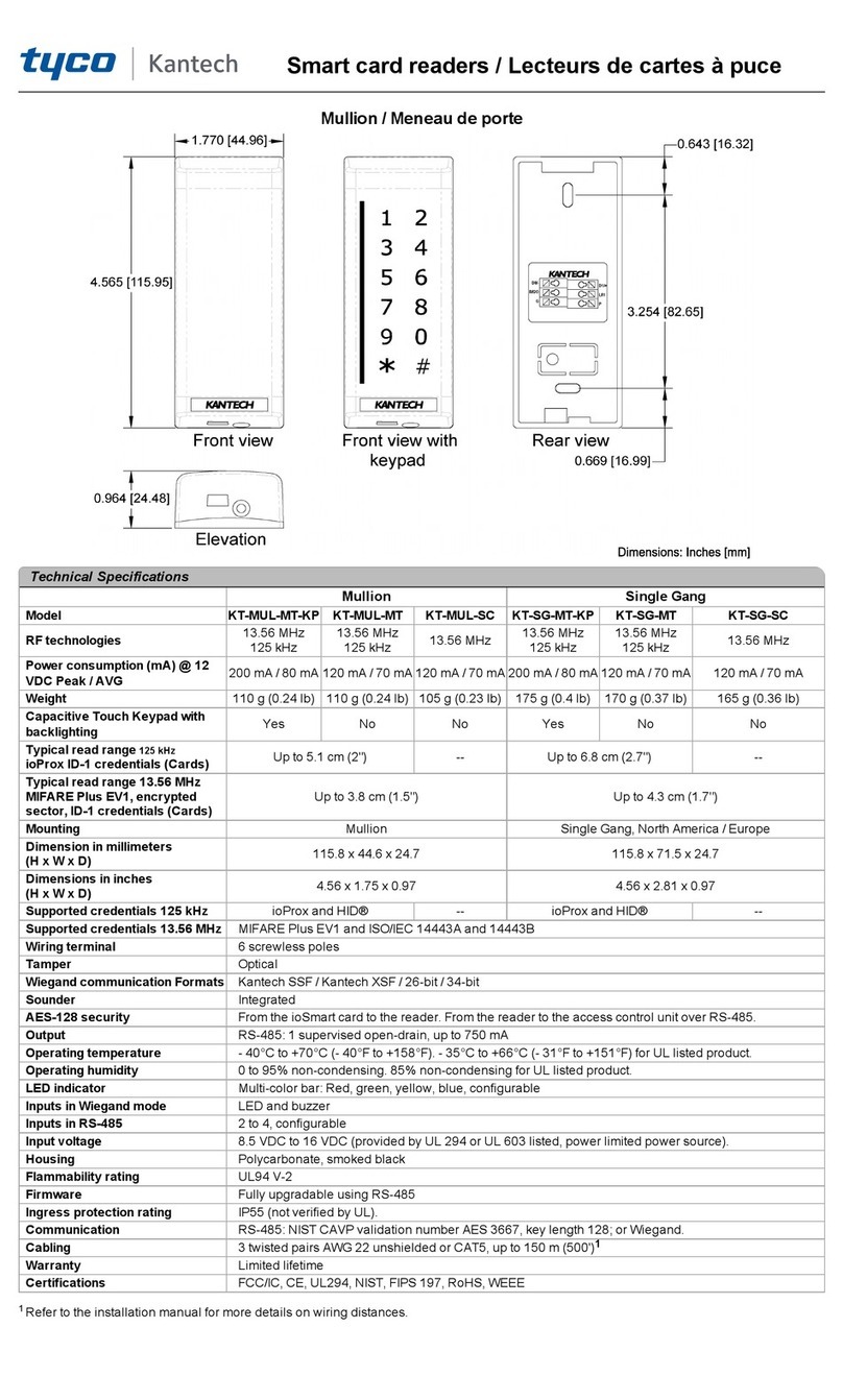
Descrizione del prodotto e suo funzionamento
Il lettore di transponder TR22AxxKNX è un apparecchio
EIB/KNX in esecuzione per montaggio ad incasso dedicato al
controllo accessi con tessera transponder; personalizzabile,
versatile e modulare si adatta a qualsiasi applicazione (acces-
so ad uffici, camere d’ospedale, di hotel, impianti sportivi, spazi
riservati, parcheggi, ecc.).
Non installare in bagni, piscine o ambienti simili.
L’apparecchio è dotato di due ingressi fisici ON/OFF disponibili
per il controllo del contatto porta aperta/chiusa o di altri segnali
(contatto finestra, tirante allarme bagno ecc.).
Sul dispositivo sono presenti due relè per la gestione della ser-
ratura e per il comando della “luce di cortesia” o per altro uso.
Sul frontale del lettore sono segnalate, tramite 4 icone illumina-
te, le seguenti funzioni (in caso di controllo camera Hotel):
“accesso concesso” o “accesso negato”
“richiesta soccorso”
“rifare camera”
“camera occupata” o “non disturbare”
I LED e le icone possono essere configurati per segnalare altri
stati od eventi.
La lettura del transponder avviene posizionando lo stesso di
fronte al lettore, ad una distanza massima di 30 mm.
Il primo dato che viene controllato è il “numero impianto”, se il
codice è coerente, si procede alla verifica del campo “data” (se
abilitato) per verificarne la validità (se scaduta o no). Successi-
vamente controlla la “password” con tutti i codici ad essa asso-
ciati e abilitati (fasce orarie, codice cliente, codice di servizio).
Se tutte le condizioni sono verificate, si procede alla abilitazio-
ne apertura porta e, se impostato , all’accensione delle luce di
cortesia nonché all’invio del risultato della lettura su bus.
La configurazione dell’apparecchio, indirizzo fisico, parametri e
oggetti di comunicazione, avviene mediante il software ETS (
Engineering Tool Software).
Programma applicativo
Scaricabile dal sito eelectron: www.eelectron.com
Dati tecnici
Alimentazione
Alimentazione esterna: 12 /24 V AC/DC (deve essere SELV)
Consumo Massimo : 150mA
Non collegare ingressi/uscite a tensioni diverse da
quelle previste.
Ingressi
2 contatti privi di potenziale
Tensione di scansione Vn = 5 V DC
Corrente scansione In a contatto chiuso = 5mA per canale
Uscite a relè
2 contatti NA 24 V AC/DC, 2A (AC1), 1A (AC3)
Relè 1 (OUT1) comando serratura o uso generico
Relè 2 (OUT2) luce di cortesia o uso generico
Non collegare i relè alla tensione di rete (230V)
Lettore di transponder
Frequenza di lavoro 125 KHz
Indicatori
1 LED rosso (posteriore) per programmazione ETS
1 tasto: per programmazione ETS
1 LED Bicolore (frontale):
- Rosso “Tessera non valida”
- Verde “Accesso Concesso”
- Rosso Lampeggiante “Data scadenza non valida”
- Verde Lampeggiante “Fuori fascia oraria”
- Arancio Lampeggiante “Giorno settimana non valido”
- Arancio Fisso: Codice impianto non valido”
1 LED rosso (frontale): Segnalazione impostabile
1 LED ambra (frontale): Segnalazione impostabile
1 LED verde (frontale): Segnalazione impostabile
Collegamenti
Linea bus:
Terminale di connessione bus, conduttore max 0,8mm Ø
Alimentazione 12/24 VAC/DC (SELV):
Morsetti a vite, conduttore sezione max. 1.0 mm2
Uscite ON/OFF
Morsetti a vite, conduttore sezione max. 1.0 mm2
Ingressi ON/OFF prive di potenziale
Morsetti a vite, conduttore sezione max. 1.0 mm2
Lunghezza massima cavi in ingresso: 10 metri
Schema di Connessione
Dati meccanici e Dimensioni d’ingombro
Custodia: in materiale plastico
Colore: Grigio Chiaro Verniciato (TR22A0xKNX)
Antracite (TR22A1xKNX)
Bianco (TR22A2xKNX)
Dimensioni: (alt. x larg. x prof.): 78 x 110 x 37.1 mm
Peso: ca. 120 g.
Montaggio: In scatola da incasso rettangolare da 2 o 3 unità
modulari o in scatola tonda Ø60mm.
Sicurezza elettrica
Conforme alla Direttiva Bassa Tensione 2014/35/UE
Grado di inquinamento (secondo EN 60664-1): 2
Grado di protezione (secondo EN 60529): IP 20
Classe di protezione (secondo EN 61140): III
Classe di sovratensione (secondo EN 60664-1): III
Bus: tensione di sicurezza SELV DC 24 V
Soddisfa EN 50491-3 e EN60950
Requisiti EMC
Conforme alla Direttiva EMC 2014/30/UE
Rispettati EN 50491-5 e EN301489
Condizioni di impiego
Secondo norma EN50491-2
Temperatura ambiente durante il funzionamento: 0°C + 45°C
Temperatura di stoccaggio: - 20 + 55 C
Umidità relativa: max 90 % non condensante
Omologazione
Omologato KNX/EIB
Marcatura CE
Conforme alle direttive EMC, RED e LVD
Posizione indicatori ed elementi di comando
1234
5
6
7
8
KNX 9
10
(11)
12
13
14
15
VISTA FRONTALE CON VETRO INSERITO
Connessioni:
1 alimentazione 12/24 V AC/DC (deve essere SELV) SELV)
2 alimentazione 12/24 V AC/DC (deve essere SELV)
3 contatto NA relè 1 (OUT1) (deve essere SELV)
4 contatto NA relè 2 (OUT2) (deve essere SELV)
5 comune relè OUT1 + OUT2 (deve essere SELV)
6 ingresso 1 privo di potenziale (IN1)
7 ingresso 2 privo di potenziale (IN2)
8 comune IN1+IN2
11 terminale di connessione bus:
- polo negativo NERO
+ polo positivo ROSSO
Indicatori ed elementi di comando:
9 LED di programmazione ETS
10 Tasto di programmazione ETS
12 Led 4
13 Led 3
14 Led 2
15 Led bicolore rosso / verde
Avvertenze per l‘installazione
L’apparecchio deve essere impiegato per installazione fissa
in ambienti chiusi, spazi asciutti, incassato in custodie.
IMPORTANTE
Il dispositivo non deve essere connesso a linee di
tensione 230 VAC.
Utilizzare per l’alimentazione ausiliaria una sorgente di a-
limentazione SELV diversa da quella del bus KNX non
essendo questa compatibile con dispositivi come elettro-
serrature, interruttori, etc..
Se il dispositivo viene installato in una scatola assie-
me ad altri apparecchi questi devono essere SELV.
Rispettare le prescrizioni di sicurezza elettrica.
L’apparecchio deve essere installato e messo in servizio
da un installatore abilitato.
Devono essere osservate le norme in vigore in materia di
sicurezza e prevenzione antinfortunistica.
L’apparecchio non deve essere aperto. Eventuali appa-
recchi difettosi devono essere fatti pervenire alla sede
competente.
L’installazione deve rispettare le normative e gli standard
vigenti del paese relativo.
Montaggio e collegamento
Descrizione generale
Per effettuare la messa in servizio occorre poter accedere al
tasto di programmazione (10) che si trova sul lato posteriore
della custodia. In fase di installazione prevedere lunghezze
di collegamento dei cavi che permettano l’estrazione
dell’insieme apparecchio/telaio di montaggio dalla scatola da
incasso.
Collegamento del lettore di transponder alla linea bus
Inserire il terminale di connessione al bus KNX/EIB (11),
precedentemente collegato al cavo bus, nella fessura
guida del morsetto bus integrato che si trova sul lato po-
steriore del dispositivo.
Far scorrere il morsetto bus fino all’arresto.
Montaggio nella scatola da incasso
Per il montaggio del dispositivo nella scatola da incasso
utilizzare esclusivamente le viti in dotazione con
l’apparecchio.
Per altre informazioni visitate il sito www.eelectron.com
eelectron spa
Via Monteverdi 6
I-20025 Legnano (MI) - Italia

TR22A01KNXFI04020001
Transponder Reader
TR22A0xKNX–Light Grey
TR22A1xKNX–Anthracite
TR22A2xKNX–White
Product and Applications description
The Transponder Reader TR22AxxKNX is an EIB/KNX wall
mounting device suitable to access control application.
This device can be used in any kind of building (Hotel, Hospi-
tal, Offices, Parking, etc..) where the access control application
is required.
Do not install in bathrooms, swimming
pools and similar environments.
The device is equipped with two binary inputs (potential free
contacts) that can be used, for instance, to control whether the
door lock has been opened or closed or other signals coming
from external switches/contacts (i.e. windows, bathroom emer-
gency alarms, etc..).
The transponder reader is equipped also with two output relays
which can be used for any purposes, typically to open the door
or turning on the courtesy light inside the room.
The product provides on the front side four LEDs in order to
enlighten 4 icons to display the following states (e.g. in case of
Hotel management):
Access Allowed/Not Allowed
SOS request
Service Call (clean room, etc..)
Client status (“Busy room” or “Do not Disturb”)
The LEDs and icons can be configured in associaton with other
alarms or events.
The transponder reader can reads cards or keys at a maximum
distance of 30mm from the front side.
The access control follows a sequence where the “build num-
ber” has been checked at first, then the “data” to check if it has
been elapsed or not, next the password ID for cli-
ent/guest/service identification, then the enabled entrance tim-
ing window. In case card reading pass all checks the door is
opened and, if set, the courtesy light inside is switched on. At
the same time the Transponder Holder can send the reading
response to the bus.
The device configuration for commissioning in terms of physi-
cal address, group addresses and parameters is done with
ETS ( Engineering Tool Software) through a download of the
Application Program.
Application Program
Downloadable from eelectron website: www.eelectron.com
Technical Specifications
Power Supply
External Aux. Voltage: 12/24 V AC/DC (must be SELV)
Maximum current : 150mA
Do not connect input/output with voltages different than
specified
Inputs
2 potential free contacts
Input signal voltage Vn = 5 V DC
Input signal current at close contact = 5mA per channel
Outputs
2 relays NO 24 V AC/DC, 2 A (AC1), 1A (AC3)
Relay 1 (OUT1) door lock or general purpose
Relay 2 (OUT2) courtesy light or general purpose
Do not connect relays to mains (230V)
Transponder Reader features
Operating Frequency 125 KHz
Display and Control Elements
1 LED red for ETS programming
1 programming push button
1 LED red/green (front):
- Red: “Access Not Allowed”
- Green: “Access Allowed”
- Red Blinking: “Grant Date not valid”
- Orange: “Build Number not valid”
- Orange Blinking: “Day of week not valid”
- Green Blinking: “Hour Renge not valid”
1 LED red (front): free signalling
1 LED amber (front): free signalling
1 LED verde (front): free signalling
Connections
Bus line:
bus terminal connector block, single core max 0,8mm Ø
External Power Supply 12/24 VAC/DC (SELV):
Screw terminal block
Conductor cross section max.1.0 mm2
Output relays
Screw terminal block
Conductor cross section max.1.0 mm2
Inputs signals (potential free)
Screw terminal block
Conductor cross section max.1.0 mm2
Max cable length: 10 meters
Wiring Diagram
Physical specifications and Dimensions
Housing: plastic
Colours: Light Grey Varnished (TR22A02KNX),
Anthracite (TR22A12KNX)
White (TR22A22KNX)
Dimensions: (W x H x D): 110 x 78 x 37.1 mm
Weight: approx. 120 g.
Installation: Flash mounting in 2 or 3 modules or wall round box
Ø60mm, 40mm deep
Electrical Safety
Compliant with LV Directive 2014/35/UE
Pollution degree : 2 (according to EN 60664-1)
Protection class IP20 (according to EN 60529)
Safety class: III (according to EN 61140)
Overvoltage category: III (according to EN 60664-1)
Bus: safety extra low voltage SELV DC 24 V
Device complies with EN 50491-3 e EN60950
Electromagnetic compatibility
Complies with EMC Directive 2014/30/UE
Complies with EN 50491-5 and EN301489
Environmental specifications
Climatic conditions: complies with EN50491-2
Ambient operating temperature: 0°C + 45°C
Storage temperature: - 20 + 55 C
Relative humidity: max 90 % without condensation
Certification
KNX/EIB certificate
CE Mark
According with EMC, RED and Low Voltage Directives
Location and Function of operating and display elements
1234
5
6
7
8
KNX 9
10
(11)
Terminals and Operating Elements:
1 Power Supply 12/24 V AC/DC (must be SELV) (SELV)
2 Power Supply 12/24 V AC/DC (must be SELV)
3 OUT 1 terminal relay 1 (NO) (must be SELV)
4 OUT2 terminal relay2 (NO) (must be SELV)
5 COM Outputs
7 IN 1 (potential free)
8 IN 2 (potential free)
8 COM Inputs
9 Programming LED
10 Programming push button
11 Bus Connection Terminal:
Black = bus polarity (-) bus NERO
Red = bus polarity (+)
12 Led 4
13 Led 3
14 Led 2
15 Led red/green
Installation Instructions
The device may be used for permanent indoor installations in
dry locations within wall boxes.
WARNING
The device must not be connected to 230V AC ca-
bles.
Do not use KNX bus to feed the auxiliary power supply;
this source is not compatible with electric door lock, and
other non KNX equipments, use a SELV power supply
Device must be installed in a single box; any other
device in the same box must be SELV.
The prevailing safety rules must be heeded.
The device must be mounted and commissioned by an
authorised installer.
The applicable safety and accident prevention regula-
tions must be observed.
The device must not be opened. Any faulty devices
should be returned to manufacturer.
For planning and construction of electric installations,
the relevant guidelines, regulations and standards of
the respective country are to be considered.
Mounting and Wiring hints
General Description
The device configuration (KNX physical address assignment)
is done by pressing the programming push button (10) lo-
cated in the back side of the housing. Please take care dur-
ing installation to leave connection wires long enough in or-
der to remove the device easily from the wall box for com-
missioning.
Connecting bus cables
Connect each single KNX/EIB bus core inside the ter-
minal block (11) observing bus polarity .
Slip the bus connection block (11) into the guide slot
placed on the back side of this device and press the
block down to the stop.
Wall box mounting
Use for mounting only screws included.
For further information please visit www.eelectron.com
eelectron spa
Via Monteverdi 6
I-20025 Legnano (MI) - Italia
Web: www.eelectron.com
Other manuals for TR22A01KNX
1
This manual suits for next models
1
Table of contents
Languages:
Other Eelectron Card Reader manuals
