STYL SR272B Instructions for use

Document Title
Revision: B
SR272A; SR272B Hardware User Manual
DAR/T272D/DES/2032
Hardware User Manual
SIRIUS Contactless Transit Reader
(Configuration A/B)
Model No: SR272A; SR272B

Document Title
Revision: B
SR272A; SR272B Hardware User Manual
DAR/T272D/DES/2032
Revision History
Date
Revision
Description
Author
21 Dec 2016
A
First Release
Vincent Tay
28 Sept 2017
B
Add Configuration B
Vincent Tay

Document Title
Revision: B
SR272A; SR272B Hardware User Manual
DAR/T272D/DES/2032
Table of Contents
1. Introduction ....................................................................................................................................1
1.1. About the Reader.................................................................................................................... 1
1.2. Terminology, Abbreviations and Notations............................................................................1
2. Reader Specification ....................................................................................................................... 2
3. Board type and stack up ................................................................................................................. 3
3.1. Main Board.............................................................................................................................. 3
3.2. SAM Board ..............................................................................................................................4
3.3. Antenna Board ........................................................................................................................5
3.3.1. (Configuration A)................................................................................................................. 5
3.3.2. (Configuration B)................................................................................................................. 6
3.4. Assembly Diagram...................................................................................................................7
4. Reader Connection.......................................................................................................................... 8
5. Operational Precautions ...............................................................................................................10
5.1. General Safety Instructions................................................................................................... 10
5.2. Installation ............................................................................................................................10
5.3. Reader Status Indicators.......................................................................................................10
5.4. Battery Safety Information ...................................................................................................11
5.5. Fuse Information...................................................................................................................11
6. FCC Compliance Statement...........................................................................................................12

Document Title
Revision: B
SR272A; SR272B Hardware User Manual
DAR/T272D/DES/2032
1 of 12
1. Introduction
This document aims to describe how to operate the SR272A; SR272B hardware, and the
connectivity of the reader to the host.
1.1. About the Reader
The SR272A; SR272B reader is NFC reader with support for SIM-sized smartcards.
•Supports up to 8 ISO7816 Class A, B and C (5 V, 3 V, and 1.8 V) SIM-sized smartcards.
•Supports ISO14443 microprocessor cards with T=0 or T=1 protocol with PPS, and
ISO14443 memory cards.
•User-controllable RGB status LED.
•User-controllable buzzer.
•Driver-free PC/SC operating mode.
The reader complies with FCC/CE regulations, TUV shock-and vibration tests for use in transit
environments.
1.2. Terminology, Abbreviations and Notations
B2B
Board-to-Board
CCID
Chip card interface device.
DPC
Dynamic Power control
EEPROM
Electrically Erasable Programmable Read-Only
Memory
Host
Host device refers to the controlling device
operating the reader.
LED
Light-Emitting Diode
PCSC
Personal Computer/Smart Card specification
RF
Radio frequency
RGB
Red, Green, Blue
SAM
Secure Access Module
UART
Universal Asynchronous Receiver/Transmitter
USB
Universal Serial Bus

Document Title
Revision: B
SR272A; SR272B Hardware User Manual
DAR/T272D/DES/2032
2 of 12
2. Reader Specification
Physical
Dimensions
104 × 67 × 41(mm)
(Config B Antenna size is 195 x 135 x 1 (mm))
Weight
160g
Technical
Operating System
Linux
Processor
Application: Freescale IMX6 ARM 9 Cortex
RF: Maxim M3 Secure Cortex
Memory
2GB DDR RAM and 2GB NAND Flash
Power Supply
DC12V via 10pin connector
DC5V via USB
Current Consumption
270mA (Typical)
NFC Features
Transmit Frequency
13.56 MHz
Protocols supported
ISO/IEC 14443-1 to 14443-4 A/B, ISO/IEC15693, Sony
Felica™, ECMA-340, ECMA-352 and ISO18092
Read Range
Memory based Card: up to 10cm, CPU based Card: up to 8.5cm
Cards supported
All ISO14443-X contactless cards
Interface Features
Alerts
Buzzer
LED Indicators
Power LED (X2), RGB status LED
Data Communication
USB Interface
USB Type C
Serial Interface
RS-232, RS-485
Environmental
Operating Temperature
-10°C ~ 70°C
Storage Temperature
-20°C ~ 85°C
Humidity
0% to 95%
Shock
Acceleration: 20g, Pulse duration: 11ms, Direction: 3
perpendicular axes, No of shocks: 5 per axes
Vibration
IEC-68 part 2-31 and DIN EN 60721-3-5 class 5M2
Anti-Corrosion
Conformal coated
Document Title
Revision: B
SR272A; SR272B Hardware User Manual
DAR/T272D/DES/2032
3 of 12
3. Board type and stack up
Three PCB assemblies make up the SR272A and SR272B Reader.
•Main Board –Application controller of SR272A; SR272B Reader
•SAM Board –RF controller of SR272A; SR272B Reader
•Antenna Board assembly –Antenna of SR272A Reader and Antenna of SR272B
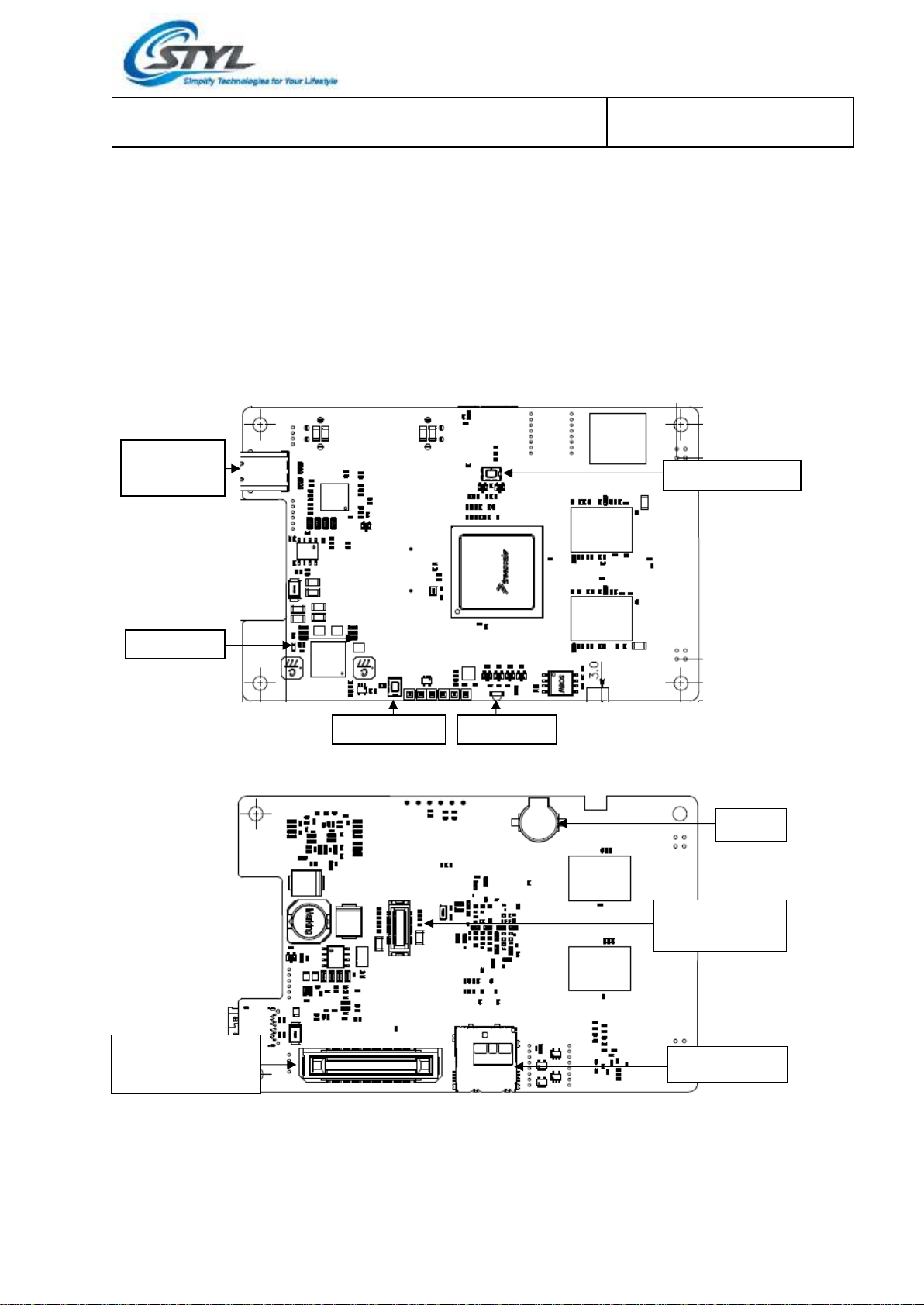
3.1. Main Board
Figure 1: Main Board (Top)
Figure 2: Main Board (Bottom)
Power LED
Reset Switch
Status LED
Program Switch
USB-C1
Connector
Connectivity
Board Connector
Buzzer
Micro SD Slot
Main to SAM
B2B Connector

Document Title
Revision: B
SR272A; SR272B Hardware User Manual
DAR/T272D/DES/2032
4 of 12
3.2. SAM Board
Figure 3: SAM Board (Top)
Figure 4: SAM Board (Bottom)
HOST 10-pin
Connector
Main to SAM
Board Connector
Local Antenna
Connector
Remote Antenna
Connector
PCSC/CCID
USB-C2
Connector
SAM
Power LED
SAM Slots
SAM Expander
connector
2
3
1
4
RTC Battery
Holder
Document Title
Revision: B
SR272A; SR272B Hardware User Manual
DAR/T272D/DES/2032
5 of 12
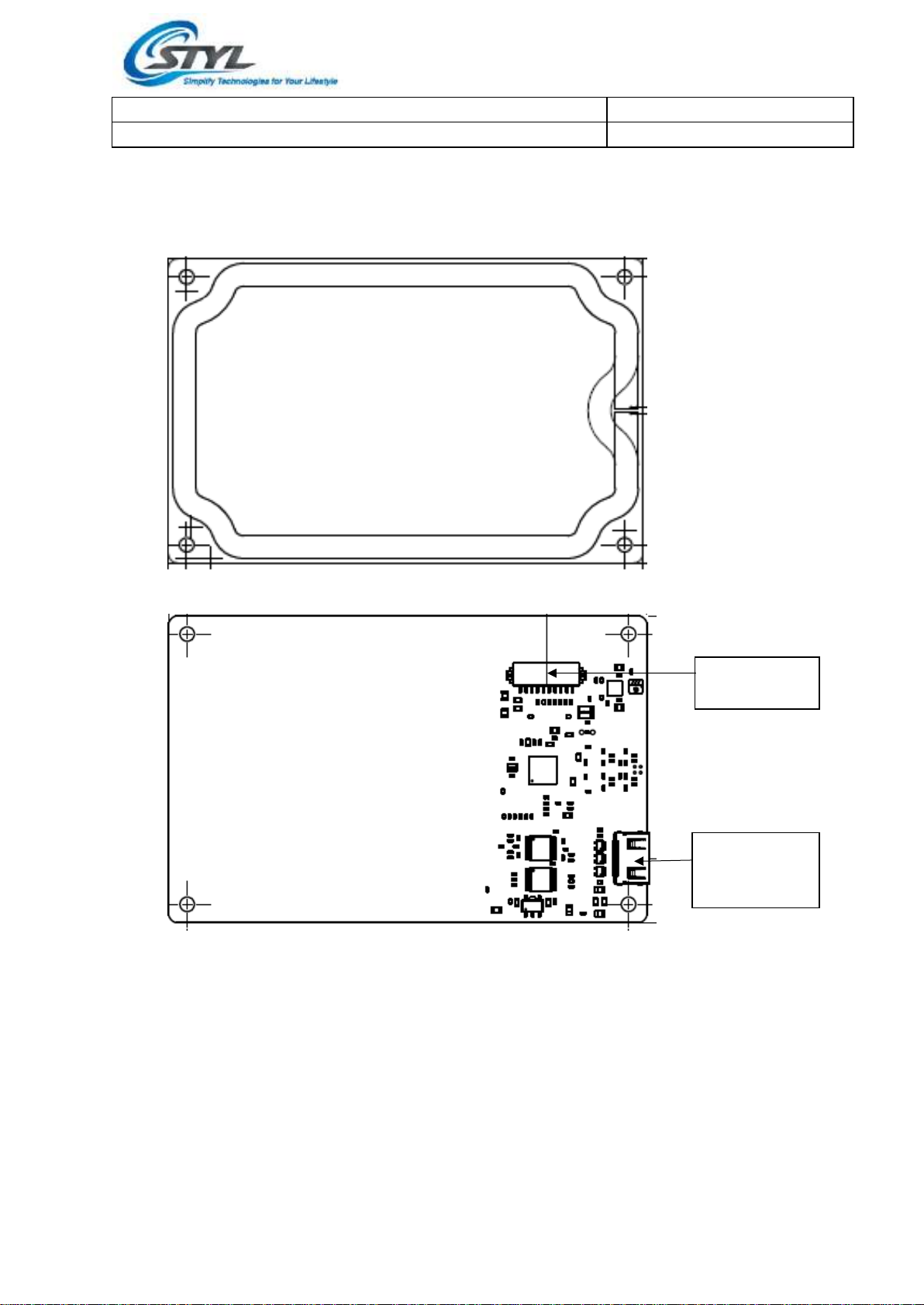
3.3. Antenna Board
3.3.1. (Configuration A)
Figure 5: Antenna Board (Top)
Figure 6: Antenna Board (Bottom)
Local Antenna
Connector
Remote
Antenna
Connector

Document Title
Revision: B
SR272A; SR272B Hardware User Manual
DAR/T272D/DES/2032
6 of 12
3.3.2. (Configuration B)
Figure 7: Antenna Board
Local Antenna
Connector
Remote Antenna
Connector
Document Title
Revision: B
SR272A; SR272B Hardware User Manual
DAR/T272D/DES/2032
7 of 12
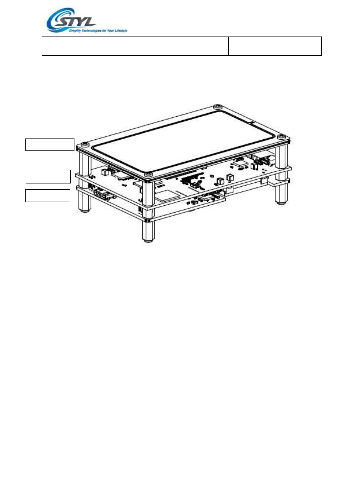
3.4. Assembly Diagram
The assembled reader stack-up diagram is shown below.
Figure 8: Assembled SR272A Reader
Antenna Board
Main Board
SAM Board
This manual suits for next models
1
Table of contents
Other STYL Card Reader manuals


