Effekta KS5 Series User manual

Grid-Connected Inverter
Installation and Operation Manual
KS5-Series
3000ST / 5000DT
202111 Ver:1.0

User Manual
2
Contents
1.Introduction ....................................................................................................................3
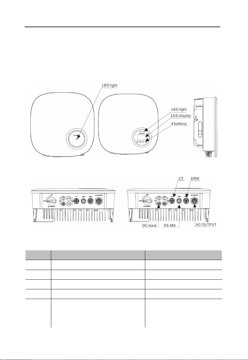
1.1 Product Description .....................................................................................3
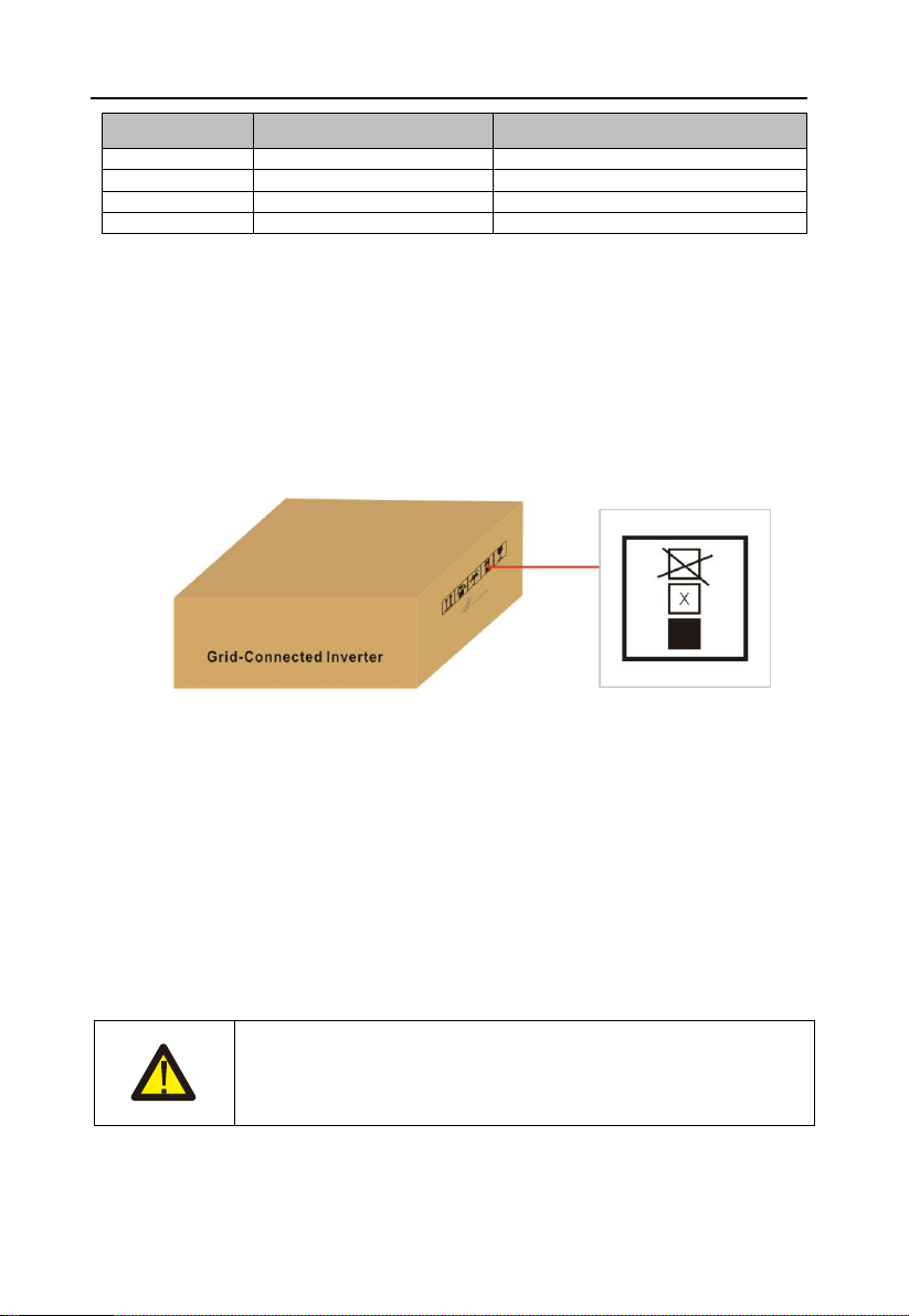
1.2 Packaging ...................................................................................................4
1.3 Optional Packaging .....................................................................................4
1.4 Inverter Storage...........................................................................................5
2. Safety Instructions ...........................................................................................................5
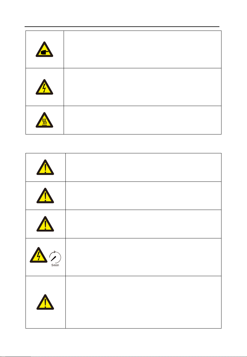
2.1 Safety Symbols.......................................................................................................5
2.2 General Safety Instructions.....................................................................................6
2.3 Notice for Use.........................................................................................................7
3. Overview .........................................................................................................................8
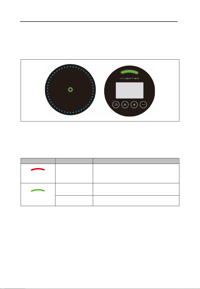
3.1 Front Panel Display ................................................................................................8
3.2 LED Status Indicator Light ......................................................................................8
3.3 Keypad (Optional)...................................................................................................8
3.4 LCD (Optional)........................................................................................................9
4. Installation .....................................................................................................................10
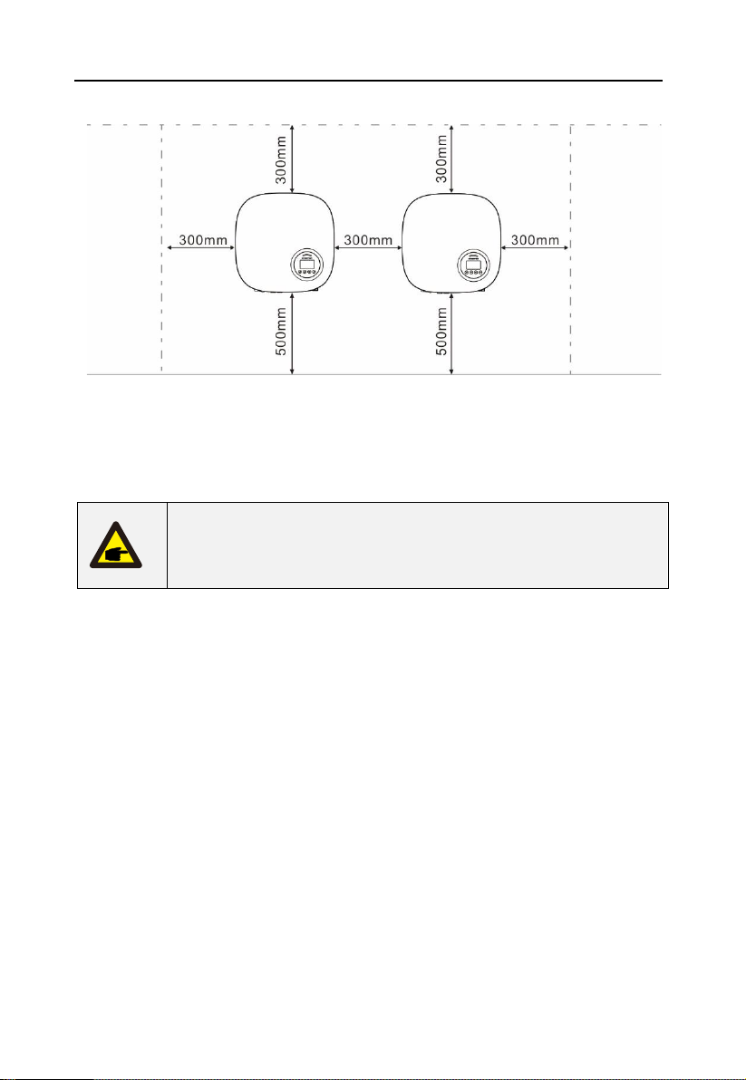
4.1 Select a Location for the Inverter ..........................................................................10
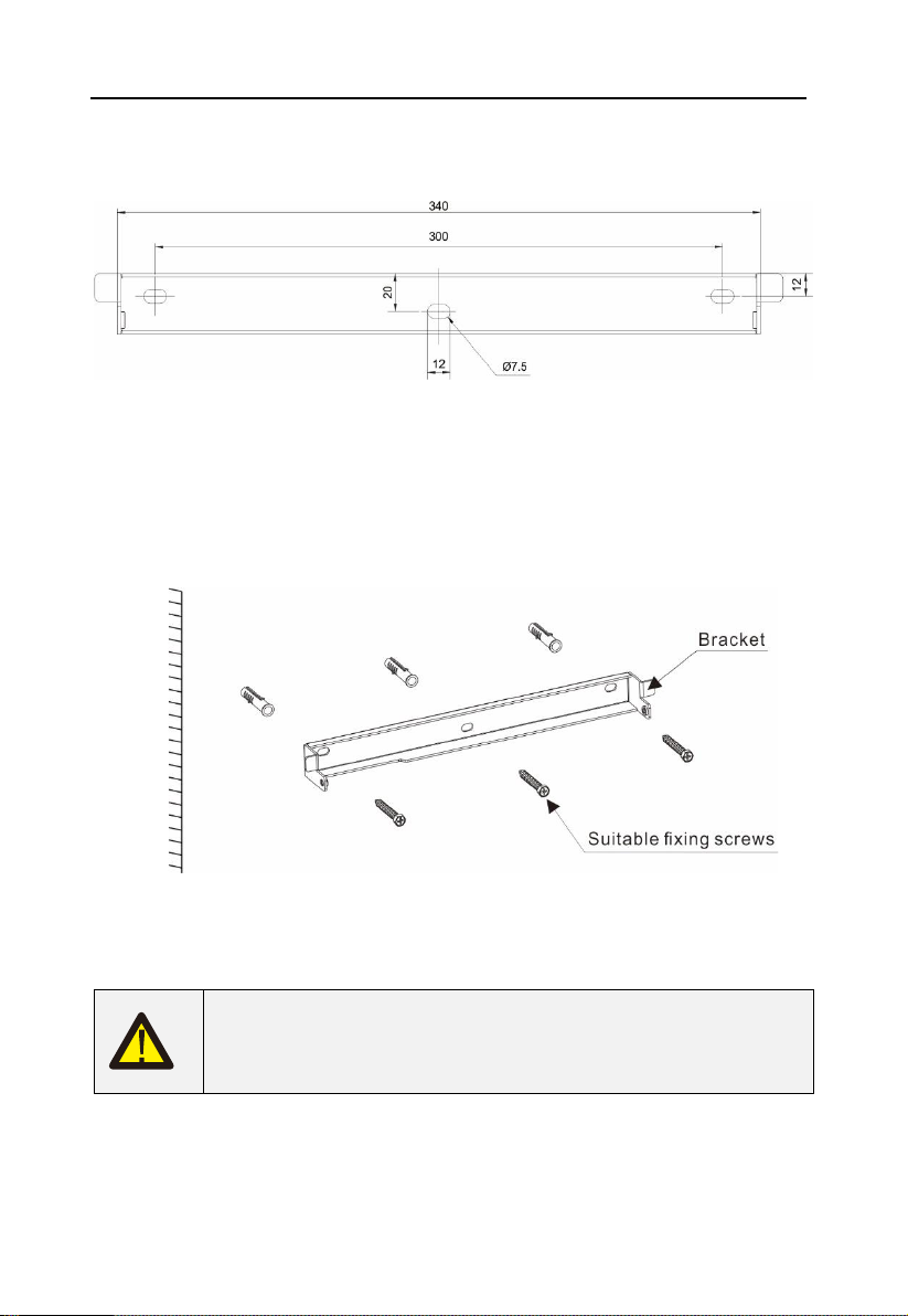
4.2 Mounting the Inverter............................................................................................12
4.3 Electrical Connections ..........................................................................................14
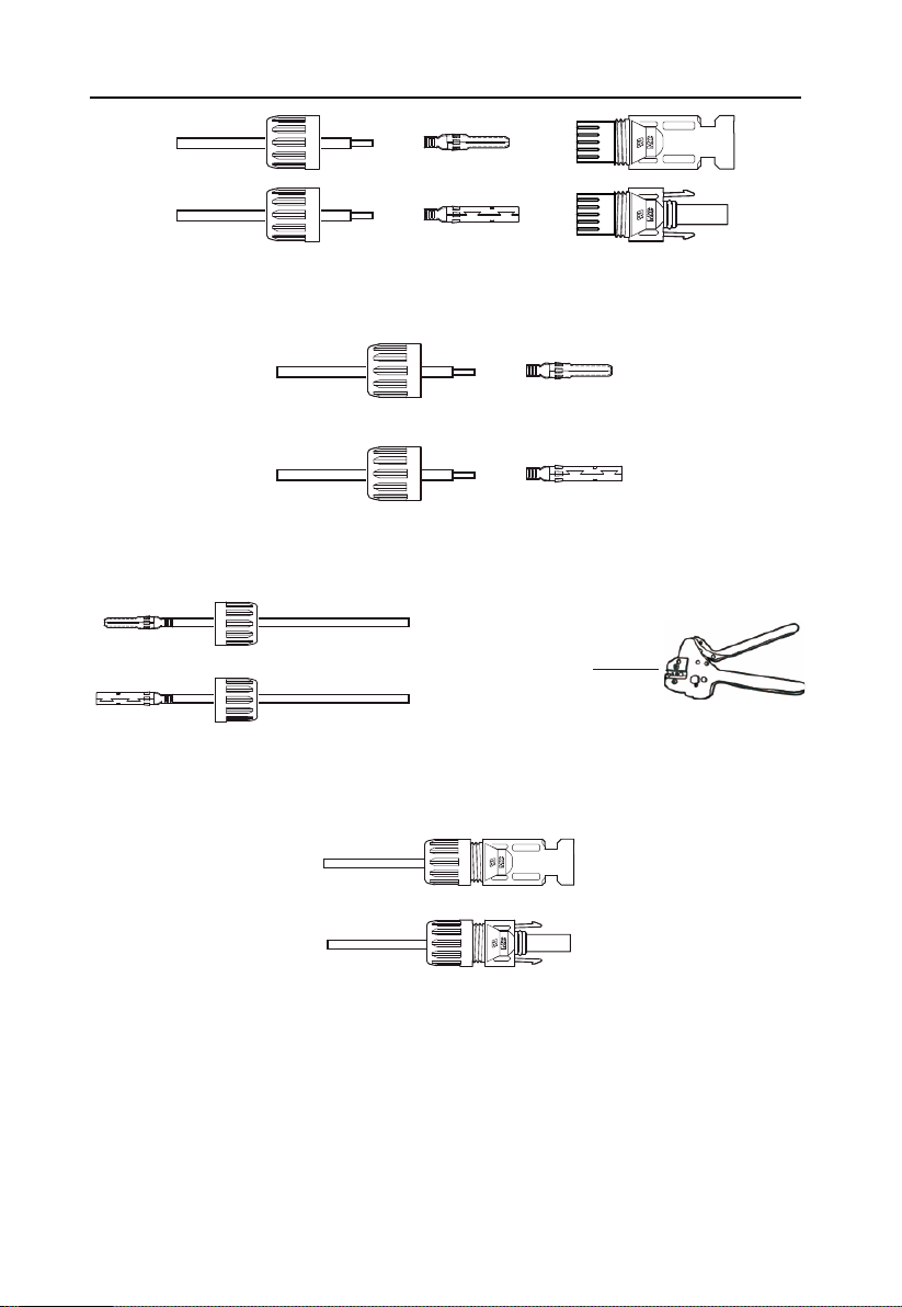
4.3.1 Connect PV side of inverter ........................................................................14
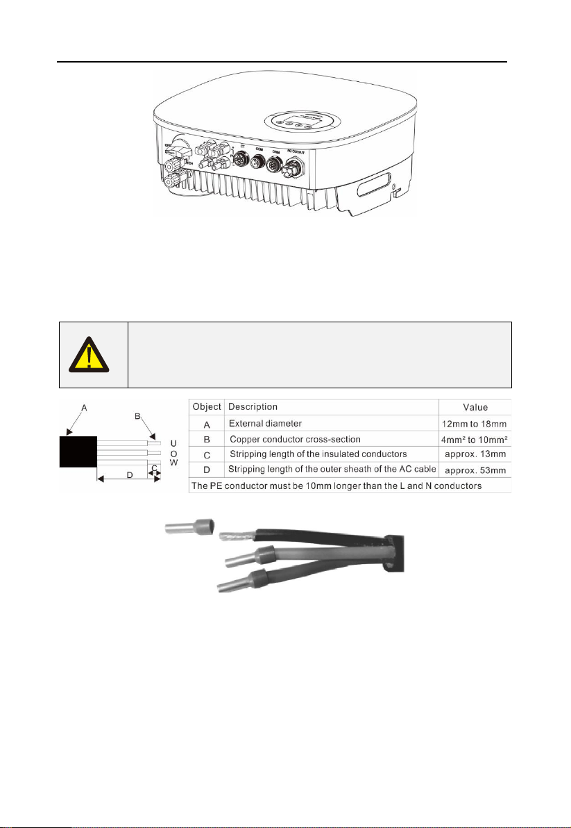
4.3.2 Connection of AC output.............................................................................17
4.3.3 External ground connection ........................................................................19
4.3.4 Max, over current protection device (OCPD)...............................................20
4.3.5 Inverter monitoring connection....................................................................21
4.3.6 CT connections (optional) ...........................................................................22
4.3.7 DRED port connections (optional)...............................................................23
5. Start & Stop...................................................................................................................24
5.1 Start the Inverter...................................................................................................24
5.2 Stop the Inverter ...................................................................................................24
6.Operation........................................................................................................................25
6.1 Setup-Technicians Only ........................................................................................26
6.1.1 Set Date/Time.............................................................................................27
6.2 Inquire ..................................................................................................................27
6.3 Statistics...............................................................................................................27
7. Maintenance..................................................................................................................28
8.Trouble shooting.............................................................................................................29
9. Specifications ................................................................................................................32
Inverter Technical Parameter Table -1.........................................................................32
Inverter Technical Parameter Table -2.........................................................................33
10. Quality Assurance........................................................................................................34

User Manual
3
1.Introduction
1.1 Product Description
KS5 series single phase inverters integrate DRM and backflow power control function, that
could suitable for smart grid requirement.
LCD display is Optional
Figure 1.2a Bottom side view Figure 1.2b Bottom side view (others)
Object
Description
DVC class
1
PV1, PV2
DVC C
2
AC OUTPUT
DVC C
3
DRM
DVC A
4
CT
DVC A
5
COM
DVC A

User Manual
4
1.2 Packaging
When you receive the inverter, ensure that all the parts listed below are included:
Object
Description
Model
Number
1
PV grid tie inverter
1
2
Wall/pole bracket
3
Locking screws
2
4
DC connector
1 pair for KS5 3000ST,
2 pairs for others
5
AC connector
1
6
Manual
1
7
OT terminal
6
8
Explpsion-proof screws
3/3
1.3 Optional Packaging

User Manual
5
Object
Description
Number
1
DRM connector
1
2
CT connector
1
3
WiFi/GPRS Stick
1
4
1xCT and com cable
1
1.4 Inverter Storage
Proper storage is required if the inverter is not installed immediately.
• Store the inverter in the original packing case.
• The storage temperature must be always between -40° C and +70° C, and the storage
relative humidity must be always between 0 and 95%, non-condensing.
• In case of stacking storage, the number of stacking layers should never exceed the limit
marked on the outer side of the packing case.
• The packing case should be upright.
• If the inverter has been stored more than half a year, the qualified personnel should
thoroughly check and test it before using.
2. Safety Instructions
Improper use may result in potential electric shock hazards or burns. This manual contains
important instructions that should be followed during installation and maintenance. Please
read these instructions carefully before use and keep them for future reference.
Contact the nearest hazardous waste disposal station when the products or components are
discarded.
2.1 Safety Symbols
Safety symbols used in this manual, which highlight potential safety risks and important safety
information, are listed as follows:
WARNING:
WARNING symbol indicates important safety instructions, which if not
correctly followed, could result in serious injury or death.

User Manual
6
NOTE:
NOTE symbol indicates important safety instructions, which if not
correctly followed, could result in some damage or the destruction of
the inverter.
CAUTION:
CAUTION, RISK OF ELECTRIC SHOCK symbol indicates important
safety instructions, which if not correctly followed, could result in
electric shock.
CAUTION:
CAUTION, HOT SURFACE symbol indicates safety instructions, which
if not correctly followed, could result in burns.
2.2 General Safety Instructions
WARNING:
Only devices in compliance with SELV (EN 69050) may be connected
to the RS485 and USB interfaces.
WARNING:
Please don't connect PV array positive(+) or negative(-) to ground, it
could cause serious damage to the inverter.
WARNING:
Electrical installations must be done in accordance with the local and
national electrical safety standards.
WARNING:
Do not touch any inner live parts until 5 minutes after disconnection
from the utility grid and the PV input.
WARNING:
To reduce the risk of fire, over-current protective devices (OCPD) are
required for circuits connected to the Inverter.
The DC OCPD shall be installed per local requirements. All
photovoltaic source and output circuit conductors shall have
disconnects that comply with the NEC Article 690, Part II.

User Manual
7
CAUTION:
Risk of electric shock. Do not remove cover. There is no user
serviceable parts inside. Refer servicing to qualified and accredited
service technicians.
CAUTION:
The PV array (Solar panels) supplies a DC voltage when they are
exposed to sunlight.
PV module used with inverter must have an IEC 61730 Class A rating.
2.3 Notice for Use
The inverter has been constructed according to the applicable safety and technical guidelines.
Use the inverter in installations that meet the following specifications ONLY:
1. Permanent installation is required.
2. The electrical installation must meet all the applicable regulations and standards.
3. The inverter must be installed according to the instructions stated in this manual.
4. The inverter must be installed according to the correct technical specifications.
5. To startup the inverter, the Grid Supply Main Switch (AC) must be switched on, before the
solar panel's DC isolator shall be switched on. To stop the inverter, the Grid Supply Main
Switch (AC) must be switched off before the solar panel's DC isolator shall be switched off.

User Manual
8
3. Overview
3.1 Front Panel Display
LCD display is Optional.
Figure 3.1 Front Panel Display
3.2 LED Status Indicator Light
The LED status indicator can display red and green. When the indicator light is on, it indicates
that there is power. When the indicator light is red, it indicates the alarm state; when the
indicator light is green, it indicates the operation state.
Light
Status
Description
ALARM
ON
Alarm or fault condition is detected.
OPERATION
ON
The inverter is operating properly.
FLASHING
Grid Connected countdown
Table 3.1 Status Indicator Light
3.3 Keypad (Optional)
There are four keys in the front panel of the Inverter from left to right: ESC, UP, DOWN and
ENTER keys. The keypad is used for:
• Scrolling through the displayed options (the UP and DOWN keys);

User Manual
9
• Access to modify the adjustable settings (the ESC and ENTER keys).
3.4 LCD (Optional)
The four-line Liquid Crystal Display (LCD) is located on the front panel of the Inverter, which
shows the following information:
• Inverter operation status and data;
• Service messages for operator;
• Alarm messages and fault indications.
You can also get information via WiFi / GPRS.

User Manual
10
4. Installation
4.1 Select a Location for the Inverter
To selects location for the inverter, the following criteria should be considered:
• Do not install in small closed spaces where air can not circulate freely. To avoid
overheating , always make sure the flow of air around the inverter is not blocked.
• Exposure to direct sunlight will increase the operational temperature of the inverter and
may cause output power limiting. EFFEKTA recommends inverter installed to avoid direct
sunlight or raining.
• To avoid overheating ambient air temperature must be considered when choosing the
inverter installation location. EFFEKTA recommends using a sun shade minimizing direct
sunlight when the ambient air temperature around the unit exceeds 104°F/40°C.
Figure4.1 Recommended Installation locations
• Install on a wall or strong structure capable of bearing the weight.
• Install vertically with a maximum incline of +/-5° . If the mounted inverter is tilted to an
angle greater than the maximum noted, heat dissipation can be inhibited, and may result in
less than expected output power.
• When 1 or more inverters are installed in one location, a minimum 300mm clearance should
be kept between each inverter or other object(if a canopy is added, a distance of 50cm must

User Manual
11
also be kept). The bottom of the inverter should be 500mm clearance to the ground.
Figure 4.2 Inverter Mounting clearance
• Visibility of the LED status indicator lights and the LCD located at the front panel of the
inverter should be considered.
• Adequate ventilation must be provided if the inverter is to be installed in a confined space.
NOTE:
Nothing should be stored on or placed against the inverter.

User Manual
12
4.2 Mounting the Inverter
Dimensions of wall bracket:
Figure 4.3 Inverter wall mounting
Please see Figure 4.4 and Figure 4.5 for instruction on mounting the inverter.
The inverter shall be mounted vertically. The steps to mount the inverter are listed below:
1. According to the figure 4.2, select the mounting height of the bracket and mark the
mounting holes. For brick walls, the position of the holes should be suitable for the
expansion bolts.
Figure 4.4 Inverter wall mounting
2. Make sure the bracket is horizontal and the mounting holes (in Figure 4.4 ) are marked
correctly. Drill the holes into the wall or pillar at your marks.
3. Use the suitable screws to fix the bracket to the wall.
WARNING:
The inverter must be mounted vertically.
4.Lift up the inverter (be careful to avoid body strain), and align the back bracket on the
inverter with the convex section of the mounting bracket. Hang the inverter on the mounting
bracket and make sure the inverter is secure (see Figure 4.5).

User Manual
13
Figure 4.5 Wall Mount Bracket
5. Use M5*16 screws in accessory to lock the inverter to the mount bracket.

User Manual
14
4.3 Electrical Connections
4.3.1 Connect PV side of inverter
The electrical connection of the inverter must follow the steps listed below:
1. Switch the Grid Supply Main Switch (AC) OFF.
2. Switch the DC Isolator OFF.
3. Assemble PV input connector to the Inverter.
Check whether the polarity of the connecting cable of the photovoltaic
string is correct, and ensure that the open circuit voltage under any
condition does not exceed the upper limit of the inverter input value of
600V.
Please don't connect PV array positive or negative pole to the ground, it
could cause serious damages to the inverter.
Before connection, please make sure the polarity of the output voltage of
PV array matches the "DC+" and "DC-" symbols.
Figure 4.6 DC+ Connector Figure 4.7 DC- Connector

User Manual
15
Check the positive and negative polarity of the PV strings, and connect the PV connectors
to the right terminals. Serious damages to the inverter and connector over temperature may
occur.
Please use approved DC cable for PV system.
Cable type
Cross section(mm²)
Range
Recommended
value
Industry generic PV
cable(model:PV1-F)
4.0-6.0 (12-10AWG)
4.0 (12AWG)
The steps to assemble the DC connectors are listed as follows:
1.Strip off the DC wire for about 7mm, Disassemble the connector cap nut.

User Manual
16
Figure 4.8 Disassemble the Connector Cap nut
2. Insert the wire into the connector cap nutand contact pin.
Figure 4.9 Insert the Wire into the Connector Cap nut and contact pin
3. Crimp the contact pin to the wire using a proper wire crimper.
Figure 4.10 Crimp the contact pin to the wire
4. Insert the contact pin to the top part of the connector and screw up the cap nut to the top
part of the connector.
Figure 4.11 Connector with Cap nut Screwed on
5. Then connect the DC connectors to the inverter. Small click will confirm connection.
Сrim ping plier

User Manual
17
Figure 4.12 Connect the DC Connectors to the Inverter
4.3.2 Connection of AC output
For all AC connections, 4-10mm² 105 XJ cable is required to be used. Please make sure the
resistance of cable is lower than 1 ohm. If the wire is longer than 20m, it's recommended to
use 10mm² cable.
WARNING:
There are"L ","N'','' PE'' symbols marked inside the connector, the Line
wire of grid must be connected to "L " terminal; the Neutral wire of grid must
be connected to "N" terminal; the Earth of grid must be connected to "PE" .
b. Insert the conductor into the suitable ferrule acc. to DIN 46228-4 and crimp the contact.
c. Unscrew the swivel nut from the threaded sleeve and thread the swivel nut and threaded
sleeve over the AC cable.

User Manual
18
d. Insert the crimped conductors L, N and PE into the corresponding terminals and tighten
the screw with a hex key wrench screwdriver(size:2.5, 1.2-2.0N·m). Ensure that all conductors
are securely in place in the screw terminals on the bush insert.
e. Screw the swivel nut onto the threaded sleeve. This seals the AC connector and provides
strain relief for the AC cable. When doing so, hold the bush insert firmly by the locking cap.
This ensures that the swivel nut can be screwed firmly onto the threaded sleeve.
f. Assembly the plug shell ,adapter as below picture, Push the adapter and Shell by hand
until a “Click” is heard or felt.
g. Plug the AC connector into the jack for the AC connection by hand until a “Click” is

User Manual
19
heard or felt.
Figure 4.13 Connect the AC Connector to the Inverter
Note: Connection for Split phase grid.
When connect to 208/220/240V split phase, please connect L1 to "L"
terminal, L2 to "N" terminal. Also connect earth to ground terminal.
4.3.3 External ground connection
An external ground connection is provided at the right side of inverter.
Prepare OT terminals. Use proper tooling to crimp the lug to the terminal.
Figure4.13 Connect the external grounding conductor
Note: When earth fault occurs,the machine cannot be connected to the
grid, the LED red light is on, and the LCD displays the fault code F07 until
the fault is resolved.

User Manual
20
4.3.4 Max, over current protection device (OCPD)
To protect the inverter's PV and AC grid connection conductors, EFFEKTA recommends
installing breakers that will protect against overcurrent. The following table defines OCPD
ratings for the KS5 single phase inverters.
Inverter
Rated
output
voltage(V)
Rated output
current (A)
Current for protection
device (A)
KS5-3000ST
230
13
20
KS5-5000DT
230
21.7
40
Table 4.3 OCPD level of power grid
Inverter
Rated input
voltage(V)
Max. input
current (A)
Current for protection
device (A)
KS5-3000ST
600
15
20
KS5-5000DT
600
15
40
Table 4.4 PV OCPD ratings
This manual suits for next models
2
Table of contents
Other Effekta Inverter manuals
Popular Inverter manuals by other brands

Santerno
Santerno SUNWAY TG610 1000V TE OD installation guide

BorMann
BorMann BIW4005 owner's manual

gefran
gefran SIEIDrive ADL300 Functions description and parameters list

2hp
2hp Brst manual

Power Science
Power Science CF-1500-12 Series user manual

SolarTorrent
SolarTorrent 1000W Grid Tie Power Inverter user guide

TECO-Westinghouse Motor
TECO-Westinghouse Motor GA7200 Operation manual

Mastervolt
Mastervolt MASS SINE 400 Series quick start guide

Agilent Technologies
Agilent Technologies 8648A Operating and service manual

GMDE
GMDE GEatom 306KTL Insallation Instructions

Moso
Moso ST5KTL manual

Aaronia
Aaronia BPSG 4 manual