Predator 59188 User manual
SUPER QUIET
INVERTER
GENERATOR
7600 RUNNING WATTS
9500 MAX STARTING WATTS
Owner’s Manual & Safety Instructions
Save This Manual Keep this manual for the safety warnings and precautions, assembly,
operating, inspection, maintenance and cleaning procedures. Write the product’s serial number in the
back of the manual (or month and year of purchase if product has no number). Keep this manual and the
receipt in a safe and dry place for future reference. 23a
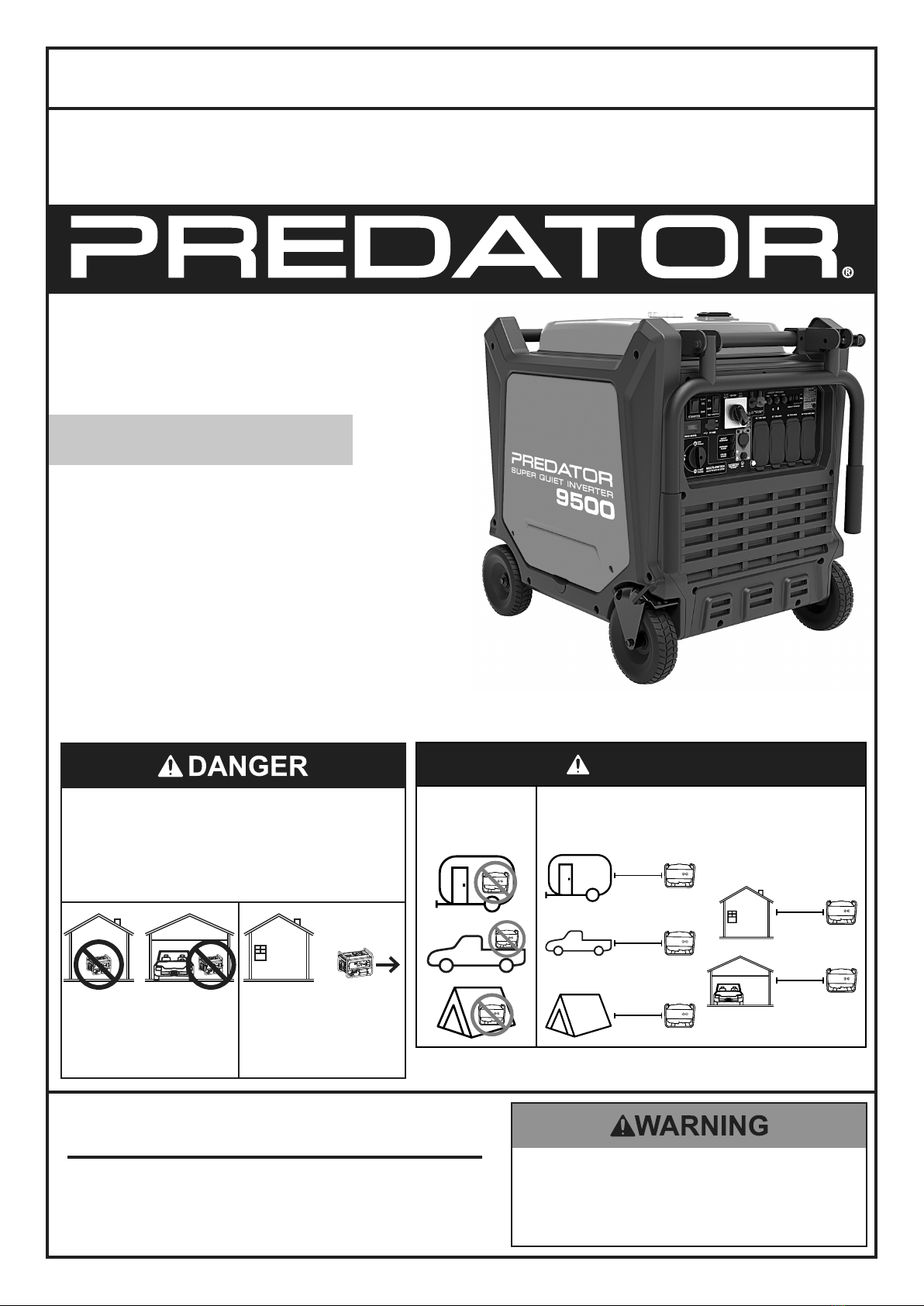
Using a generator indoors CAN
KILL YOU IN MINUTES.
Generator exhaust contains
carbon monoxide. This is a poison
you cannot see or smell.
NEVER use inside
a home or garage,
EVEN IF doors and
windows are open.
Only use OUTSIDE
and far away from
windows, doors,
and vents.
When unpacking, make sure that the product is intact
and undamaged. If any parts are missing or broken,
please call 1-888-866-5797 as soon as possible.
Copyright©2022 by Harbor Freight Tools®. All rights reserved.
No portion of this manual or any artwork contained herein may be reproduced in
any shape or form without the express written consent of Harbor Freight Tools.
Diagrams within this manual may not be drawn proportionally. Due to continuing
improvements, actual product may differ slightly from the product described herein.
Tools required for assembly and service may not be included.
Read this material before using this product.
Failure to do so can result in serious injury.
SAVE THIS MANUAL.
DANGER
Do not use in
trailers, truck
beds, or tents.
Use at least 20 feet away from
people, animals, and structures
with exhaust pointed away.
20′
20′
20′
20′
20′
Visit our website at: http://www.harborfreight.com
Page 2 For technical questions, please call 1-888-866-5797. ITEM 59188
Table of Contents
Specifications ............................................................... 2
Safety ...........................................................................3
Setup ............................................................................8
Operation.....................................................................10
Maintenance................................................................ 18
Troubleshooting........................................................... 22
Parts List and Diagram................................................ 26
Warranties ................................................................... 30
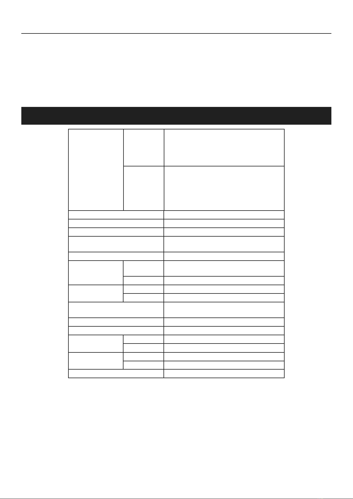
Specifications
Generator
Output
120/240 VAC, 60 Hz, 63.3 / 31.7 A, 1 Phase
12 VDC, 8 A (nominal)
5V USB, 3.1A
7600 Running Watts
9500 Maximum Starting Watts
Receptacles
2 x GFCI NEMA #5-20R (3-prong, 120 VAC)
1 x NEMA #L5-30R (3-prong, 120 VAC)
1x NEMA #L14-30R (4-prong, 120/240 VAC)
1 x 12 VDC Two Pin Outlet
2 x USB-A Outlets
Parallel Kit Terminals
Displacement 459 cc
Compression Ratio 8.5:1
Battery for Electric Start 12V, 12Ah Lead Acid
Engine Type Horizontal Single Cylinder
4-stroke, OHV
Cooling System Forced air cooled
Fuel Type 87+ octane, stabilizer-treated
unleaded gasoline
Capacity 6.60 Gallon / 25.00 Liter
Engine Oil Type SAE 10W-30
Capacity 37 fl. oz.
Run Time @ 25% Load
with full tank 18.5 hr.
Sound Level at 23 feet, 25% load 67 dB(A)
Bore x Stroke 92mm x 69mm
Spark Plug Type BPR6ES (NGK) or equivalent
Gap 0.027"– 0.031"
Valve Clearance Intake 0.0039"– 0.0059"
Exhaust 0.0059"– 0.0078"
Engine Speed 2560 - 3410 RPM
The emissions control system for this Engine is warranted for standards set by the
U.S. Environmental Protection Agency and by the California Air Resources Board (also known as CARB).
For warranty information, refer to the last pages of this manual.

Page 3
For technical questions, please call 1-888-866-5797.
ITEM 59188
SAFETYOPERATIONMAINTENANCE SETUP
WARNING SYMBOLS AND DEFINITIONS
This is the safety alert symbol. It is used to alert you to potential
personal injury hazards. Obey all safety messages that
follow this symbol to avoid possible injury or death.
Indicates a hazardous situation which, if not avoided,
will result in death or serious injury.
Indicates a hazardous situation which, if not avoided,
could result in death or serious injury.
Indicates a hazardous situation which, if not avoided,
could result in minor or moderate injury.
Addresses practices not related to personal injury.
Symbol Definitions
Symbol Property or Statement
RPM Revolutions Per Minute
HP Horsepower
AWG American Wire Gauge
WARNING marking concerning
Risk of Eye Injury. Wear ANSI-approved
safety goggles with side shields.
Read the manual before
set-up and/or use.
Symbol Property or Statement
WARNING marking concerning
Risk of Hearing Loss.
Wear hearing protection.
WARNING marking concerning
Risk of Respiratory Injury.
Operate engine OUTSIDE and far away
from windows, doors, and vents.
WARNING marking concerning
Risk of Fire while handling fuel.
Do not smoke while handling fuel.
WARNING marking concerning
Risk of Fire. Do not refuel while
operating. Keep flammable
objects away from engine.
IMPORTANT SAFETY INSTRUCTIONS
WARNING! Read all instructions.
Failure to follow all instructions listed below may result in fire, serious injury and/or DEATH.
The warnings and precautions discussed in this manual cannot cover all possible conditions and
situations that may occur. It must be understood by the operator that common sense and caution
are factors which cannot be built into this product, but must be supplied by the operator.
SAVE THESE INSTRUCTIONS
Page 4 For technical questions, please call 1-888-866-5797. ITEM 59188
SAFETY OPERATION MAINTENANCESETUP
Setup Precautions
1. Gasoline fuel and fumes are flammable, and
potentially explosive. Use proper fuel storage
and handling procedures. Do not store fuel
or other flammable materials nearby.
2. Have multiple ABC class fire extinguishers nearby.
3. Operation of this equipment may create sparks that
can start fires around dry vegetation.
A spark arrestor may be required. The operator
should contact local fire agencies for laws or
regulations relating to fire prevention requirements.
4. Set up and use only on a flat, level,
well-ventilated surface.
5. All connections and conduits from the Generator
to the load must only be installed by trained and
licensed electricians, and in compliance with all
relevant local, state, and federal electrical codes and
standards, and other regulations where applicable.
6. Connections for standby power to a building
electrical system must be made by a qualified
electrician. The connection must isolate the
Generator power from utility power, and must
comply with all applicable laws and electrical codes.
7.7. A transfer switch should be installed by aA transfer switch should be installed by a
licensed electrician in compliance with alllicensed electrician in compliance with all
applicable laws and electrical codes.applicable laws and electrical codes.
8. Wear ANSI-approved safety goggles, heavy-duty
work gloves, and dust mask/respirator during set up.
9. Use only lubricants and fuel recommended
in the Specifications chart of this manual.
10. Improper connections to a building electrical system
can allow electrical current from the Generator
to backfeed into the utility lines. Such backfeed
may electrocute utility company workers or others
who contact the lines during a power outage,
and the Generator may explode, burn, or cause
fires when utility power is restored. Consult
the utility company and a qualified electrician if
intending to use the Generator for back up power.
11. Do not operate the Generator before grounding.
The Generator must be earth-grounded
in accordance with all relevant electrical
codes and standards before operation.
12.12. Install carbon monoxide alarm(s) withInstall carbon monoxide alarm(s) with
battery backup in nearby buildings accordingbattery backup in nearby buildings according
to manufacturer’s instructions.to manufacturer’s instructions.
Operating Precautions
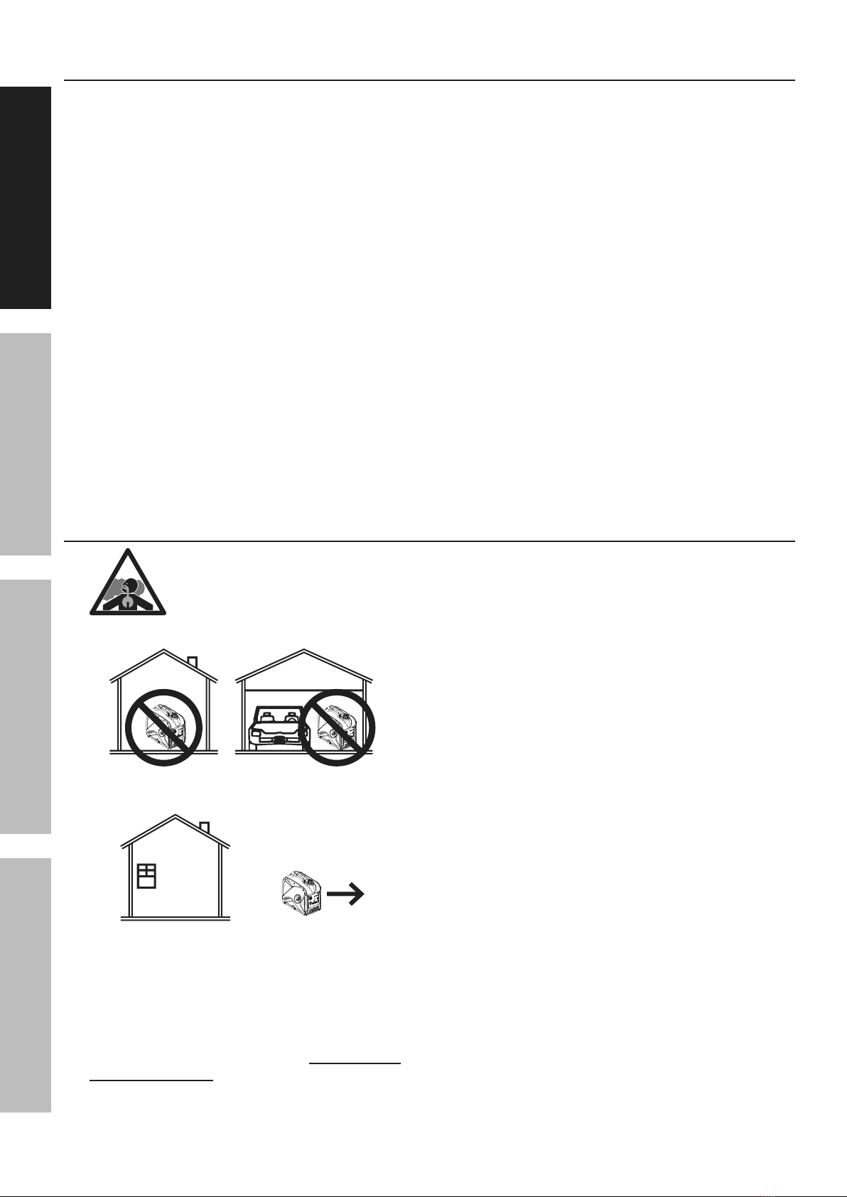
1. CARBON MONOXIDE HAZARD
Using a generator indoors CAN KILL
YOU IN MINUTES.
Generator exhaust contains
carbon monoxide. This is a poison
you cannot see or smell.
OFF
RUN
START
LOWOIL OVERLOADOUTPUT
PARALLELOUTLETS
RESET
AC120V
RESET
DC12V
ESC
THROTTLE
OFF
RUN
START
LOWOIL OVERLOADOUTPUT
PARALLELOUTLETS
RESET
AC120V
RESET
DC12V
ESC
THROTTLE
NEVER use inside a home or garage,
EVEN IF doors and windows are open.
OFF
RUN
START
LOWOIL OVERLOADOUTPUT
PARALLELOUTLETS
RESET
AC120V
RESET
DC12V
ESC
THROTTLE
Only use OUTSIDE and far away from windows,
doors, and vents.
2. CARBON MONOXIDE SHUTOFF
DANGER! TO PREVENT SERIOUS
INJURY AND DEATH FROM
CARBON MONOXIDE INHALATION:
The Carbon Monoxide sensor is an additional
layer of protection only. Do not use the
Generator in any area or situation that will
allow carbon monoxide to accumulate.
• FLASHING RED LIGHT:
Dangerous levels of carbon monoxide gas have
built up and generator will shutoff.
Leave immediately until area has aired
out. Move Generator to well-ventilated
area before operation.
• FLASHING YELLOW LIGHT:
Carbon monoxide sensor malfunction.
Sensor needs service. Do not use the
Generator until the sensor is working
properly. For technical questions, please call
1-888-866-5797.
NOTE: Yellow light flashes onceNOTE: Yellow light flashes once
after starting to indicate passing self-after starting to indicate passing self-
check and is functioning normally.check and is functioning normally.
Carbon Monoxide sensor must only be serviced
by qualified technician to restore it to original
settings. Do not modify or tamper with the
Carbon Monoxide sensor. Not following these
instructions can result in death or serious injury
due to Carbon Monoxide sensor malfunction.
3. Never use a generator indoors, including in
garages, basements, crawl spaces and sheds.
Opening doors and windows or using fans will NOT
prevent carbon monoxide build up in the home.
4. When using generators, keep them outdoors
and far away from open doors, windows,
and vents to avoid toxic levels of carbon
monoxide from building up indoors.

Page 5
For technical questions, please call 1-888-866-5797.
ITEM 59188
SAFETYOPERATIONMAINTENANCE SETUP
5. If you start to feel sick, dizzy, or weak while
using a generator, get to fresh air right away.
The carbon monoxide from generators can
quickly lead to full incapacitation and death.
6. Keep children away from the equipment,
especially while it is operating.
7. Keep all spectators at least six feet
from the engine during operation.
8. Fire Hazard! Do not fill gas tank while engine is
running. Do not operate if gasoline has been spilled.
Clean spilled gasoline before starting engine.
Do not operate near pilot light or open flame.
9. Do not touch engine during use.
Let engine cool down after use.
10. Never store fuel or other flammable
materials near the engine.
11. If the plugged in product operates abnormally
or unusually slow, immediately stop using the
generator as a power source. Read and adhere
to the instruction manual of the product to be
powered to make sure that it can be safely and
efficiently powered by a portable generator.
12. Before connecting an appliance or power cord
to the generator: Make sure that it is in good
working order. Faulty appliances or power cords
can create a potential for electrical shock.
13. Do not exceed the running wattage of the generator.
Make sure that the total electrical rating of the
all of the tools or appliances plugged into the
generator at the same time does not exceed that
of the generator. Check that the startup surge
will not be beyond the limit of the generator.
14. Avoid substantially overloading which will trip
the circuit breaker. Slightly overloading the
generator may not trip the circuit breaker,
but will lead to premature generator failure.
15. Do not attempt to connect or disconnect
load connections while standing in water,
or on wet or soggy ground.
16. Do not touch electrically energized parts of
the generator and interconnecting cables or
conductors with any part of the body, or with
any non-insulated conductive object.
17. Connect the generator only to a load that is
compatible with the electrical characteristics
and running wattage of the generator.
18. Insulate all connections and disconnected wires.
19. Guard against electric shock.
Prevent body contact with grounded surfaces such
as pipes, radiators, ranges, and refrigerators.
20. Only use a suitable means of transport and
lifting devices with sufficient weight bearing
capacity when transporting the generator.
21. Secure the generator on transport vehicles to
prevent it from rolling, slipping, and tilting.
22. Industrial applications must follow
OSHA requirements.
23. Do not leave the generator unattended when it is
running. Turn off the generator (and remove safety
keys, if available) before leaving the work area.
24. The generator can produce high noise levels.
Prolonged exposure to noise levels
above 85 dBA is hazardous to hearing.
Wear ear protection when operating the generator
or when working nearby while it is operating.
25. Keep access doors on enclosures locked.
26. Wear ANSI-approved safety glasses
and hearing protection during use.
27. People with pacemakers should consult their
physician(s) before use. Electromagnetic fields in
close proximity to a heart pacemaker could cause
pacemaker interference or pacemaker failure.
Caution is necessary when near the
engine’s magneto or recoil starter.
28. Use only accessories that are recommended
by Harbor Freight Tools for your model.
Accessories that may be suitable for one
piece of equipment may become hazardous
when used on another piece of equipment.
29. Do not operate in explosive atmospheres,
such as in the presence of flammable
liquids, gases, or dust. Gasoline-powered
engines may ignite the dust or fumes.
30. Stay alert, watch what you are doing and
use common sense when operating this
generator. Do not use while tired or under the
influence of drugs, alcohol or medication.
31. Dress properly. Do not wear loose clothing or
jewelry. Keep hair, clothing and gloves away
from moving parts. Loose clothes, jewelry or
long hair can be caught in moving parts.
32. Parts, especially exhaust system components,
get very hot during use. Stay clear of hot parts.
33. Do not cover the generator during operation.
34. Keep the generator and surrounding area
clean at all times. Keep generator at least
5 feet from combustible objects.
35. Do not smoke, or allow sparks, flames,
or other sources of ignition around the
equipment, especially when refuelling.
36. Use the equipment, accessories, etc.,
in accordance with these instructions and in
the manner intended for the particular type of
equipment, taking into account the working
conditions and the work to be performed.
Use of the equipment for operations different from
those intended could result in a hazardous situation.
37. Do not operate the equipment with known
leaks in the engine’s fuel system.
Operating Precautions (continued)
Page 6 For technical questions, please call 1-888-866-5797. ITEM 59188
SAFETY OPERATION MAINTENANCESETUP
38. When spills of fuel or oil occur, they must be
cleaned up immediately. Dispose of fluids and
cleaning materials as per any local, state, or
federal codes and regulations. Store oil rags in
a bottom-ventilated, covered, metal container.
39. Keep hands and feet away from moving parts.
Do not reach over or across
equipment while operating.
40. Before use, check for misalignment or binding of
moving parts, breakage of parts, and any other
condition that may affect the equipment’s operation.
If damaged, have the equipment serviced
before using. Many accidents are caused
by poorly maintained equipment.
41. Use the correct equipment for the application.
Do not modify the equipment and do not use the
equipment for a purpose for which it is not intended.
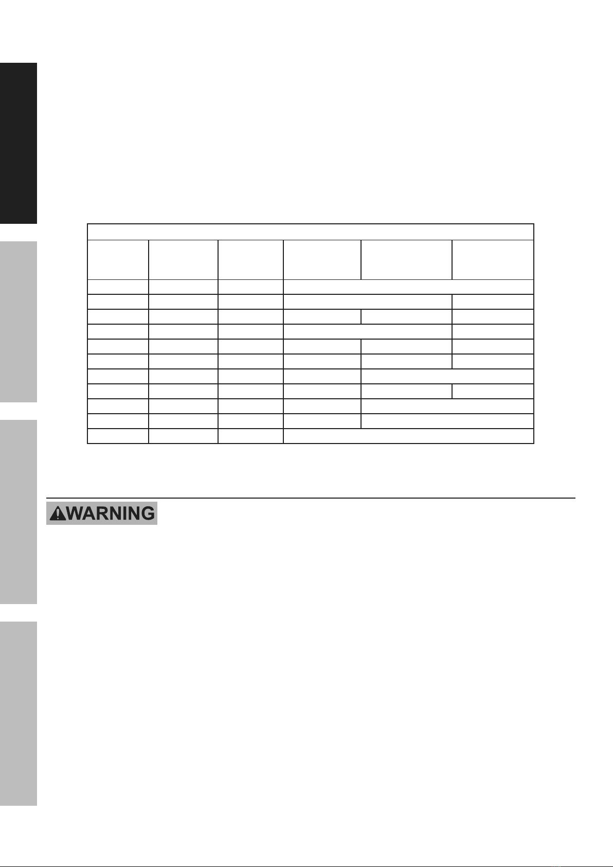
42.42. Extension Cord - Make sure your extension cord isExtension Cord - Make sure your extension cord is
in good condition. When using an extension cord, bein good condition. When using an extension cord, be
sure to use one heavy enough to carry the currentsure to use one heavy enough to carry the current
your product will draw. An undersized extensionyour product will draw. An undersized extension
cord will cause a drop in line voltage resulting in losscord will cause a drop in line voltage resulting in loss
of power and overheating.of power and overheating.
The table below shows the correct cord size to useThe table below shows the correct cord size to use
depending on cord length and nameplate amperedepending on cord length and nameplate ampere
rating. If in doubt, use the next heavier gauge.rating. If in doubt, use the next heavier gauge.
The smaller the gauge number, the heavier the cord.The smaller the gauge number, the heavier the cord.
RECOMMENDED MINIMUM WIRE GAUGE FOR EXTENSION CORDS
CURRENT
(AMPS)
Load @
120V
(WATTS)
Load @
240V
(WATTS)
0 ~ 50 ft 50 ~ 75 ft 75 ~ 100 ft
2 240 480 18 AWG
4 480 960 18 AWG 16 AWG
6 720 1440 18 AWG 16 AWG 14 AWG
8 960 1920 16 AWG 12 AWG
10 1200 2400 16 AWG 14 AWG 12 AWG
15 1800 3600 14 AWG 12 AWG 10 AWG
20 2400 4800 12 AWG 10 AWG
25 3000 6000 12 AWG 10 AWG 8 AWG
30 3600 7200 10 AWG 8 AWG
35 4200 8400 8 AWG 6 AWG
40 4800 9600 6 AWG
Parallel Kit Precautions
TO PREVENT SERIOUS INJURY, DEATH, AND GENERATOR AND/OR EQUIPMENT
DAMAGE FROM ELECTRIC SHOCK AND FIRE:
1. Follow Parallel Kit instructions provided with
Kit for connection and use of a Parallel Kit.
2. Only connect two identical Inverter Generators
together using a Parallel Kit.
3. Connect Parallel Kit only to terminals marked
“Parallel Outlets” on the front of the Generator.
4. Do not remove or connect a Parallel Kit
while the Generator is running.
5. Do not use a Parallel Kit that is
attached to only one Generator.

Page 7
For technical questions, please call 1-888-866-5797.
ITEM 59188
SAFETYOPERATIONMAINTENANCE SETUP
Service Precautions
1. Before service, maintenance, or cleaning:
a. Unplug all devices from the generator.
b. Turn the Combination Switch
to its “OFF” position.
c. Disconnect the negative battery terminal.
d. Allow the engine to completely cool.
e. Then, remove the spark plug cap
from the spark plug.
2. Keep all safety guards in place and in
proper working order. Safety guards include
muffler, air cleaner, mechanical guards,
and heat shields, among other guards.
3. Keep all electrical equipment clean and dry.
Replace any wiring where the insulation is
cracked, cut, abraded, or otherwise degraded.
Replace terminals that are worn, discolored, or
corroded. Keep terminals clean and tight.
4. Do not alter or adjust any part of the
equipment or its engine that is sealed by the
manufacturer or distributor. Only a qualified
service technician may adjust parts that may
increase or decrease governed engine speed.
5. Wear ANSI-approved safety goggles,
heavy-duty work gloves, and
dust mask/respirator during service.
6. Maintain labels and nameplates on the equipment.
These carry important information.
If unreadable or missing, contact
Harbor Freight Tools for a replacement.
7. Have the equipment serviced by a qualified repair
person using only identical replacement parts.
This will ensure that the safety of the equipment
is maintained. Do not attempt any service or
maintenance procedures not explained in this
manual or any procedures that you are uncertain
about your ability to perform safely or correctly.
8. Store equipment out of the reach of children.
9. Follow scheduled engine and
equipment maintenance.
Refueling:
1. Do not refill the fuel tank while the
engine is running or hot.
2. Do not smoke, or allow sparks, flames,
or other sources of ignition around the
equipment, especially when refuelling.
3. Do not fill fuel tank to the top.
Leave a little room for the fuel to expand as needed.
4. Refuel in a well-ventilated area only.
5. Wipe up any spilled fuel and allow excess
to evaporate before starting engine.
To prevent FIRE, do not start the engine
while the smell of fuel hangs in the air.
SAVE THESE INSTRUCTIONS.

Page 8 For technical questions, please call 1-888-866-5797. ITEM 59188
SAFETY OPERATION MAINTENANCESETUP
Set Up
Read the ENTIRE IMPORTANT SAFETY INFORMATION section at the beginning of this manual
including all text under subheadings therein before set up or use of this product.
TO PREVENT SERIOUS INJURY AND FIRE: Operate only with proper spark arrestor installed.
Operation of this equipment may create sparks that can start fires around dry vegetation.
A spark arrestor may be required.
The operator should contact local fire agencies for laws or regulations relating to fire
prevention requirements.
At high altitudes, the engine’s carburetor, governor, and any other parts that control the fuel-air ratio
will need to be adjusted by a qualified mechanic to allow efficient high-altitude use and
to prevent damage to the engine and any other devices used with this product.
Grounding
The Generator must be properly grounded in
accordance with all relevant electrical codes and
standards before operation. In many locations, local
code will not require this generator to be grounded
when used with cord and plug equipment plugged
directly into the receptacles on the generator. However,
your local regulations may require the generator to be
grounded. Contact a licensed electrician or consult
local authorities regarding local grounding requirements.
If grounding is required, have the unit grounded by a
qualified electrician if you are not qualified to do so.
General grounding instructions are as follows:
Use one of the following as the grounding electrode:
Pipe or conduit, minimum ¾ in. diameter, minimum
8 ft. long. If steel, it must have anti-corrosion coating.
Rod, stainless steel or copper- or zinc-coated steel,
minimum 5/8 in. diameter, minimum 8 ft. long.
1. Drive electrode at least 8 ft vertically into the ground.
a. If rock layer prevents vertical entry, drive at an
angle not exceeding 45 degrees from vertical.
b. If rock layer prevents angle entry, bury
electrode in horizontal trench at least 30 in. deep.
2. The upper end of electrode must be
protected if above ground level.
3. Connect a #6 AWG grounding wire (not included)
from the Grounding Terminal on the Generator
Control Panel to the buried electrode.
For additional information on grounding methods,
please see the National Electrical Code.
Note: There is a permanent conductor between
the portable generator inverter module
(Neutral Conductor) and the frame.
Electric Starter Battery Connection
For the electric start function, the included 12 VDC
Battery must be connected before first use.
1. Remove the Battery Access Panel.
2. Make sure the black strap stretches over the top of
the Battery and hooks into the Battery Platform.
3. Remove the covers from the Battery Terminals.
4. Locate the black and red battery cables.
5. Connect the red cable to the positive battery
terminal first. Then connect the black
cable to the negative battery terminal.
6. Replace the Battery Access Panel.
Note: This generator is equipped with a battery charging
circuit specific to the installed battery type that will
charge the battery when the Generator is running.
If battery needs charging during storage, make sure
to use a proper lead acid charger (not provided).
Unplug charger when battery is fully charged.

Page 9
For technical questions, please call 1-888-866-5797.
ITEM 59188
SAFETYOPERATIONMAINTENANCE SETUP
Components and Controls
OFF OFF
Engine
Switch
Economy
(ESC) Switch Voltage
Selector
CO Alarm
Light
Output
Overload
Low Oil
Combination
Switch
12VDC Receptacle
12VDC Breaker
Reset Button Ground
Terminal
120VAC 30A
L5-30R
120VAC
20A GFCI
120/240VAC 30A
L14-30R
Circuit
Breaker
120VAC
Breaker Resets
Parallel Kit
Terminals
Hour Meter
5V USB-A
Figure A: Control Panel
Recoil
Handle
Muffler
Wheel
Lock
Fuel Tank Cap Fuel Gauge
Control
Panel
Air Filter/Spark Plug/
Battery Access Panel
Combination
Switch
Oil Fill
Access
Door
Figure B: Generator Components
WARNING! TO PREVENT SERIOUS INJURY: Follow Parallel Kit instructions for
connection and use of a Parallel Kit (Parallel Kit and instructions sold separately).
Generator must be in 120V/240V mode for parallel function.

Page 10 For technical questions, please call 1-888-866-5797. ITEM 59188
SAFETY OPERATION MAINTENANCESETUP
Operation
Read the ENTIRE IMPORTANT SAFETY INFORMATION section at the beginning of this manual
including all text under subheadings therein before set up or use of this product.
Pre-Start Checks
Inspect Engine and Generator looking for damaged, loose, and missing parts before set up and starting.
If any problems are found, do not use equipment until fixed properly.
Checking and Filling Engine Oil
NOTICE: Generator is shipped without engine
oil. Engine’s crankcase MUST be filled with
oil before first use. Your Warranty is VOID if
the Engine’s crankcase is not properly filled
with oil before first use and before each use
thereafter. Before each use, check the oil level.
Engine will not start with low or no engine oil.
1. Make sure the Engine is stopped and is level.
2. On the left side of the Generator, loosen
the Screw and remove the Oil Fill
Access Door, as shown to the right.
3. Clean the top of the Oil Fill Cap / Dipstick
and the area around it. Remove the
Cap / Dipstick, turning it counterclockwise.
4. Check the oil level. The oil level should be
up to the edge of the hole as shown.
5. As needed, add the appropriate type of
oil until the oil level is at the proper level.
SAE 10W-30 oil is recommended for general use.
6. Thread the Oil Fill Cap / Dipstick back in clockwise
and replace the Oil Fill Access Door.
NOTICE: Do not run the engine with too little oil.
Engine will shut off if engine oil level is too low.
Oil Fill
Access
Door
Full Level
xxx x x x x
Oil Fill
Cap/Dipstick
Checking and Filling Fuel
WARNING! TO PREVENT SERIOUS
INJURY FROM FIRE:
Fill the fuel tank in a well-ventilated area
away from ignition sources. If the Engine
is hot from use, shut the Engine off and
wait for it to cool before adding fuel. Do not smoke.
1. Clean the Fuel Cap and the area around it.
2. Unscrew and remove the Fuel Cap.
3. Remove the Strainer and remove any dirt
and debris. Then replace the Strainer.
Note: Do not use gasoline containing more than
10% ethanol (E10). Do not use E85 ethanol. Add fuel
stabilizer to the gasoline or the Warranty is VOID.
tNote: Do not use gasoline that has been stored in a
metal fuel container or a dirty fuel container. It can
cause particles to enter the carburetor, affecting
Engine performance and/or causing damage.
4. If needed, fill the Fuel Tank to about 1 inch under
the fill neck of the Fuel Tank with 87 octane or
higher unleaded gasoline that has been treated
with a fuel stabilizer additive. Follow fuel stabilizer
manufacturer’s recommendations for use.
5. Replace the Fuel Cap.
6. Wipe up any spilled fuel and allow excess
to evaporate before starting engine.
To prevent FIRE, do not start the engine
while the smell of fuel hangs in the air.
Page 11
For technical questions, please call 1-888-866-5797.
ITEM 59188
SAFETYOPERATIONMAINTENANCE SETUP
Starting the Engine
Before Starting the Engine
a. Inspect the generator and engine.
b. Disconnect all electrical loads from the generator.
c. Fill the engine with the proper amount and type of
both stabilizer-treated unleaded gasoline and oil.
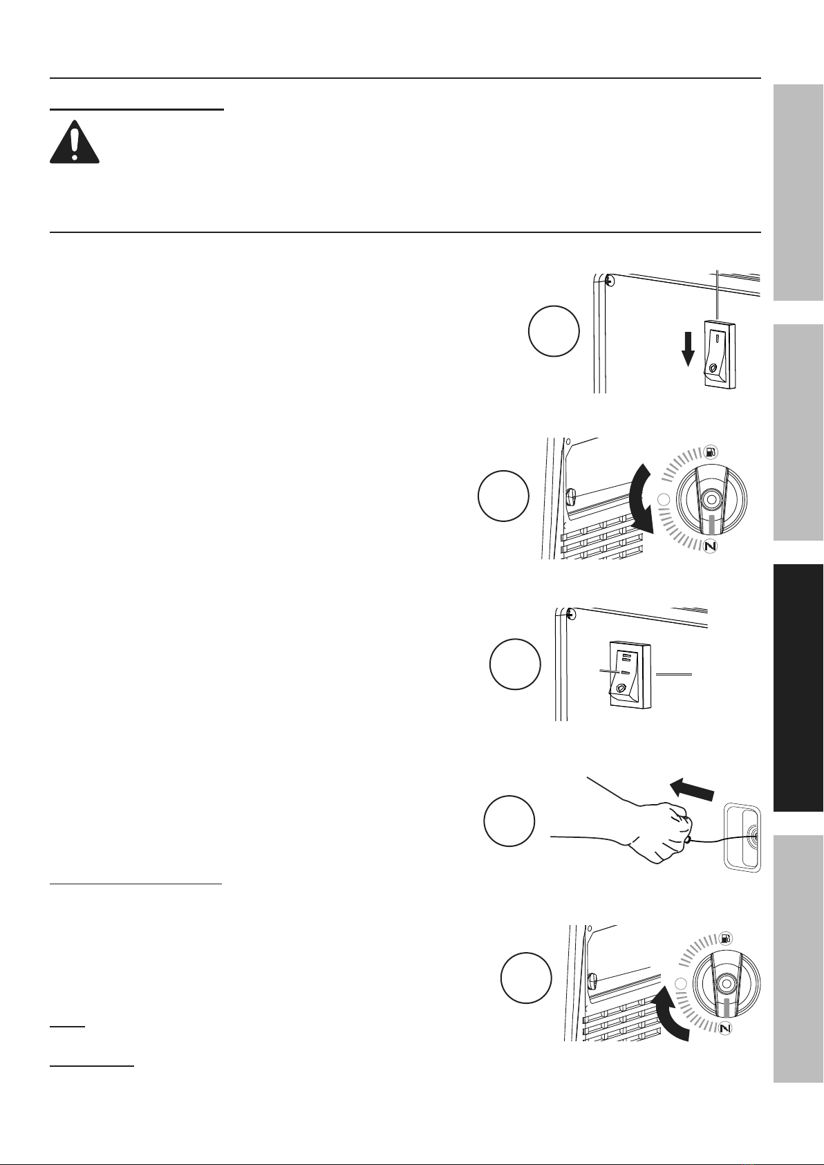
Manual Start
1. Turn the Economy Switch
to the OFF position.
2. Turn the Combination Switch
to the START position.
3. Turn the Engine Switch to the ON position.
4. Grip the Starter Handle of the Engine loosely and
pull it slowly several times to allow the gasoline to flow
into the Engine’s carburetor. Then pull the Starter
Handle gently until resistance is felt. Allow Cable to
retract fully and then pull it quickly. Repeat until the
Engine starts. Do not let the Starter Handle snap back
against the housing. Hold it as it recoils so it doesn't
hit the housing.
5. After the engine starts, allow to run for
20 seconds then turn the Combination
Switch to the RUN position.
If engine does not start:
• Check engine oil level.
Engine will not start with low or no engine oil.
• Check spark arrestor cleanliness.
Engine will not start if spark arrestor is clogged.
• For warm engine – turn Combination Switch
to RUN before trying to start it again.
Note: Moving the Combination Switch
too fast could stall the Engine.
IMPORTANT: Allow the Engine to run at no load for five minutes
after each start-up so that the Engine can stabilize.
ON
OFF
ON
START
OFF
OFF
STORAGE
RUN
START
CHOKE
ON
START
OFF
1
ECONOMY
SWITCH
2
LOW IDLE MODE
ON
OFF
ENGINE SW.
ON
START
OFF
OFF
STORAGE
RUN
START
CHOKE
ENGINE SW.
ON
START
OFF
LOW IDLE MODE
ON
OFF
ON
START
OFF
OFF
STORAGE
RUN
START
CHOKE
ON
START
OFF
3ENGINE
SWITCH
4
OFF
STORAGE
RUN
START
CHOKE
5

Page 12 For technical questions, please call 1-888-866-5797. ITEM 59188
SAFETY OPERATION MAINTENANCESETUP
Electric Start
1. Turn the Economy Switch
to the OFF position.
2. Turn the Combination Switch to the
START position.
3. Turn the Engine Switch to START
position to start the Engine. If Engine
does not start within 3 seconds,
release Starter Button. Wait at
least 10 seconds, then try again.
4. After the engine starts, allow to run for
20 seconds then turn the Combination
Switch to the RUN position.
Note: If engine does not start, check
engine oil level. Engine will not
start with low or no engine oil.
Note: If warm engine does not start,
turn Combination Switch to RUN
before trying to start it again.
Note: Moving the Combination
Switch too fast could stall the Engine.
IMPORTANT: Allow the Engine to run
at no load for five minutes after each
start-up so that the Engine can stabilize.
CARBON MONOXIDE SHUTOFF
DANGER! TO PREVENT SERIOUS INJURY AND DEATH FROM CARBON MONOXIDE INHALATION:
The Carbon Monoxide sensor is an additional layer of protection only. Do not use the
Generator in any area or situation that will allow carbon monoxide to accumulate.
• FLASHING RED LIGHT:
Dangerous levels of carbon monoxide gas
have built up. Leave immediately until
area has aired out. Move Generator to
well-ventilated area before operation.
• FLASHING YELLOW LIGHT:
Carbon monoxide sensor malfunction.
Sensor needs service. Call 1-888-866-5797 as
soon as possible. Do not use the Generator until
the sensor is working properly.
NOTE: Yellow light flashes onceNOTE: Yellow light flashes once
after starting to indicate passing self-after starting to indicate passing self-
check and is functioning normally.check and is functioning normally.
Carbon Monoxide sensor must only be serviced by qualified technician to restore it to original
settings. Do not modify or tamper with the Carbon Monoxide sensor. Not following these
instructions can result in death or serious injury due to Carbon Monoxide sensor malfunction.
ON
OFF
ON
START
OFF
OFF
STORAGE
RUN
START
CHOKE
ON
START
OFF
1
ECONOMY
SWITCH
2
LOW IDLE MODE
ON
OFF
ENGINE SW.
ON
START
OFF
OFF
STORAGE
RUN
START
CHOKE
ENGINE SW.
ON
START
OFF
LOW IDLE MODE
ON
OFF
ON
START
OFF
OFF
STORAGE
RUN
START
CHOKE
ON
START
OFF
ENGINE
SWITCH
3

Page 13
For technical questions, please call 1-888-866-5797.
ITEM 59188
SAFETYOPERATIONMAINTENANCE SETUP
Break-in Period
a. Breaking-in the Engine will help to ensure proper equipment and Engine operation.
b. The break-in period will last about 30 hours of use.
DO NOT exceed 75% of the Generator’s running wattage during this period.
• Change the engine oil after this period.
Under normal operating conditions subsequent maintenance follows
the schedule explained in the MAINTENANCE section.
Nominal 12VDC Output
1. Move the Economy (ESC) Switch to the OFF position.
2. Only use the 12 VDC receptacle to charge a 12 volt lead-acid type battery using an appropriate
charge controller. (Battery and controller not included.) The 12 VDC output is not regulated.
3. Do not connect any device to the 12 VDC terminal that draws more than 8 amps.
4. If this 12 VDC circuit protection is tripped, reduce the load, and press the Reset Button next to the outlet.
Note: Do not allow the Generator to completely run out of fuel with devices attached. A Generator’s
output may sharply spike as it runs out of fuel, causing damage to attached devices.
Connecting Electrical Loads
Familiarize yourself with the engine controls, power panel and how to start the engine
before using the Generator. Calculate the wattage of the products you will use with
the Generator and verify that the Generator can handle the total load.
WARNING! Connect only properly wired plugs to the Generator.
A plug that is spliced onto a different cord may be hazardous.
Only a qualified electrician should wire a plug onto a cord.
WARNING! Never exceed the rated capacity for this Generator,
as serious damage to the Generator and/or appliances, tools, and
equipment could result from an overload. Starting and running
wattage requirements should always be calculated when matching
this Generator’s wattage capacity to the appliance, tool, or
equipment.
Use the DC12 V Receptacle to power 12 VDC equipment.
WARNING! TO PREVENT SERIOUS INJURY: Do not charge batteries
without a proper charge controller. Do not overcharge.
a. Connect the items that require the most wattage first.
b. Connect “inductive” load appliances, tools, and equipment next. Inductive
loads are small hand tools and some small appliances.
c. Connect any lights next.
d. Voltage sensitive appliances, tools, and equipment should be the last to be connected to the Generator.
Plug voltage sensitive items such as TVs, DVD players, microwaves, and cordless telephones into a UL®
Listed voltage surge protector (not included). Then, connect the surge protector into the Generator.
IMPORTANT! Failure to connect and operate appliances, tools, and equipment in this sequence can cause
damage to the Generator, appliances, tools, and equipment and will void the Warranty of this Generator.
lSt
1,
000
400
200
1,200
Total RunningWatts
(must belessthan4,200
LargestAdditional Start-upWatts 1,200
artupWatts neededfor all loads
(must belessthan5,400
Must be
Less than
Must be
Less than

Page 14 For technical questions, please call 1-888-866-5797. ITEM 59188
SAFETY OPERATION MAINTENANCESETUP
Evenly distributed
over outlets:
IF ANY CIRCUIT BREAKERS TRIP CHECK THE FOLLOWING:
1. Make sure that ALL circuit breakers are reset
before starting the Generator again.
2. Adjust the plugs so the loads are
shared across outlet circuits.
To achieve rated output from the Generator,
distribute loads over outlets.
The generator uses a 2-circuit system to supply power to the receptacles. The loads must
be evenly distributed across receptacles to prevent overload on a single circuit. If the loads
being drawn are below the max rated wattage of the generator, yet the overload light begins
blinking or the generator shuts off, try redistributing plugs across receptacles.
120V Only (3-wire) Adaptor Cord Connected to L14-30 Receptacle:
If the overload light begins blinking or the Generator shuts off, too much wattage is being drawn from one
circuit even though the rated wattage of the Generator has not been reached. If an additional plug is connected
to one of the duplex receptacles, move the plug to the other duplex receptacle. Restart the Generator.
Note: Only half the Generator’s rated wattage, or 3800W, will be delivered through
a 120V (3-wire) adaptor cord. Exceeding this may cause overload.
240V Cord Connected to L14-30 Receptacle:
The 240V cord will draw full wattage from both circuits. If further loads
are possible, distribute them across receptacles.
Page 15
For technical questions, please call 1-888-866-5797.
ITEM 59188
SAFETYOPERATIONMAINTENANCE SETUP
Before using the Generator, check that the products
you want to plug into the unit are below the rated and
maximum wattage ratings of the Generator. Use the
Wattage Calculation Table below, and the watts listed
on your products, to help calculate multiple
wattage totals.
To use the table:
1. Add up the Running Watts for all items you
would like to use at any given time.
2. Make sure that this total is under the 7,600
running wattage of the Generator.
3. Find the single highest starting watts for
the selected items and add to the total.
4. Make sure that this total is under the 9,500
max. starting wattage of the Generator.
5. Plug in and turn on products from largest wattage
to smallest.
Example
Equipment Running
Watts
Electric Water Heater (2,000 + 0) 2,000
Television (400 + 0) 400
Lawn Mower (1,200 + 1,200) 1,200
Hand Drill (600 + 600) 600
Total Running Watts
(must be less than 7,600) 4,200
Largest Additional Start-up Watts 1,200
Total Startup Watts needed for all loads
(must be less than 9,500) 5,400
Wattage Calculation Table
Equipment Running
Watts
Total Running Watts
(must be less than 7,600)
Largest Additional Start-up Watts
Total Startup Watts needed for all loads
(must be less than 9,500)
A generator that is rated more than the minimum
required max. starting watts will last much longer than
a generator that only supplies the exact watts needed.
To Calculate Wattage
Volts and amps can be multiplied together to get watts
(volts x amps = watts).
To Calculate Additional Start-Up Watts
(If They Are Not Listed)
For equipment with a motor: Use the rated watts
amount as an estimate of additional Start-up Watts.
For most lights or heaters:
there are no additional start-up watts.
Calculating Total Wattage of Devices Used with the Generator
JOB SITE
Device Running
Watts
Additional
Start-up
Watts
Air Compressor - 1/2 HP 1000 1000
Table Saw - 10" 1700 1300
Belt Sander - 3" 1200 1200
Hand Drill - 1/2" 600 600
Halogen Work Light 1000 0
Recipricating Saw 900 900
HOUSEHOLD
Device Running
Watts
Additional
Start-up
Watts
Computer w/ Monitor 800 0
Electric Clothes Dryer 5500 500
Electric Range 2100 0
Electric Water Heater 2000 0
Light Bulb - 100 watts 100 0
Microwave - 1000 watts 1000 200
Sump Pump - 1/2 HP 1000 1100
Television 400 0
Washing Machine 1100 1100
Well Pump - 1/2 HP 1000 1000
RECREATION
Device Running
Watts
Additional
Start-up
Watts
AM/FM Radio 100 0
Electric Grill 1700 0
Inflator Pump 50 100
CD/DVD Player 100 0
Box Fan - 20" 200 200
Coffee Maker 600 0
LAWN & GARDEN
Device Running
Watts
Additional
Start-up
Watts
Hedge Trimmer 400 400
Pressure Washer 1200 1200
Lawn Mower 1200 1200
Edger 1000 1000
HEATING & COOLING
Device Running
Watts
Additional
Start-up
Watts
Central AC - 10,000 BTU 1500 1500
Furnace Fan - 1/2 HP 900 1400
Space Heater 1800 0
Window AC - 10,000 BTU 1200 600
EMERGENCY
Device Running
Watts
Additional
Start-up
Watts
Refrigerator/Freezer 700 1500
Radio 100 0
Wattage Estimate Charts
Note: Wattages listed below are estimates for that type of
equipment only. Check nameplate wattages on all loads
before connecting to Generator.

Page 16 For technical questions, please call 1-888-866-5797. ITEM 59188
SAFETY OPERATION MAINTENANCESETUP
Overload Indicator
Note: The OVERLOAD light may turn on for a few seconds as a large device starts up.
This is normal for loads approaching the capacity of this Generator.
1. The total combined load through the outlets on the Generator must not exceed the running power of the unit.
2. The OVERLOAD light will begin blinking if the generator is approaching overload limit. If the OVERLOAD light
stays on and the Generator stops producing power, the generator has been overloaded.
3. Turn off and disconnect all electrical devices and stop the Engine. Compare device
requirements to Generator rating and reduce the total wattage of connected devices if
necessary. Move anything that may be limiting Generator ventilation away.
4. Check if any circuit breakers have tripped and make sure that ALL circuit
breakers are reset before starting the Generator again.
5. Restart the Engine and reconnect devices while being careful to not overload Generator.
6. Distribute loads evenly across receptacles to achieve rated output.
Low Oil Indicator
1. If the Engine oil level is too low, the LOW OIL light turns on and the Engine will automatically shut off.
2. The Engine cannot be restarted until the proper amount of oil has been added. Add the appropriate
type of oil until the oil level is at the proper level. SAE 10W-30 oil is recommended for general use.
NOTICE: Do not run the engine with too little oil. Engine will shut off if engine oil level is too low.
Note: The LOW OIL light will blink if the Generator stops due to CO sensor shutoff. This does
not indicate low oil. Follow all instructions under Carbon Monoxide Shutoff on page 12.
Economy (ESC) Switch
1. Turn the Economy (ESC) Switch ON to limit noise and fuel consumption for lighter generator loads.
2. Turn the Economy (ESC) Switch OFF to operate engine at full speed:
a. when starting
b. when a heavy load is applied
c. when using the 12 VDC output
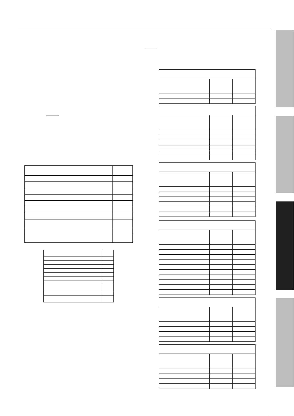
Hour Meter
The Hour Meter shows cumulative run time in hours.
Voltage Selector
The Voltage Selector allows more current to be available at 120V outlets if 240V output is not required:
• Place switch at 120V only - only 120V outlets can be used.
• Place switch at 120/240V: Both 120V and 240V outlets can be used.
NOTE: Do not change the switch while under load.
For parallel function, Switch position must be at 120/240V.
Circuit Breakers
The circuit breaker protects the Generator from overloading. The rating of the breaker and the load it protects are
marked near the breaker. Should any of the Circuit Breakers trip, the Generator will stop the electricity output. If
this happens, unplug all loads from the Generator. Then, turn the tripped Circuit Breaker to ON and re-attach
loads gradually. Note: For push-type Circuit Breakers allow a few minutes for cool-down before restarting.
ON
OFF
Page 17
For technical questions, please call 1-888-866-5797.
ITEM 59188
SAFETYOPERATIONMAINTENANCE SETUP
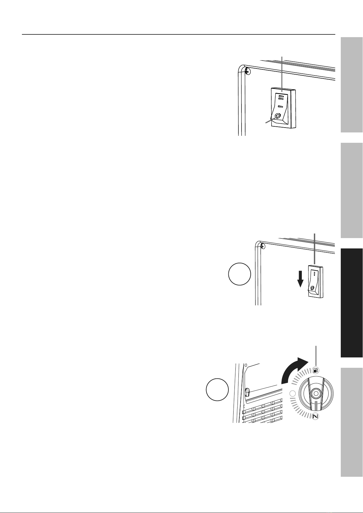
Stopping the Engine
To stop the Engine in an emergency,
turn the Engine Switch OFF.
Under normal conditions, use the following procedure to shut off the Generator:
1. Turn all electrical load devices off and unplug them from the
Generator. If the Economy Switch is ON, turn it to the OFF position.
2. Turn the Combination Switch OFF.
3. After engine stops, turn
Engine Switch to OFF.
LOW IDLE MODE
ON
OFF
ON
START
OFF
OFF
STORAGE
RUN
START
CHOKE
ON
START
OFF
ENGINE
SWITCH
ON
OFF
ON
START
OFF
OFF
STORAGE
RUN
START
CHOKE
ON
START
OFF
1
ECONOMY
SWITCH
OFF
STORAGE
RUN
START
CHOKE
Combination
Switch
2

Page 18 For technical questions, please call 1-888-866-5797. ITEM 59188
SAFETY OPERATION MAINTENANCESETUP
Maintenance
WARNING
TO PREVENT SERIOUS INJURY FROM ACCIDENTAL STARTING:
Turn the Combination Switch of the equipment to its “OFF” position, wait for the engine to cool, and
disconnect the spark plug cap before performing any inspection, maintenance, or cleaning procedures.
TO PREVENT SERIOUS INJURY FROM EQUIPMENT FAILURE:
Do not use damaged equipment. If abnormal noise, vibration, or
excess smoking occurs, have the problem corrected before further use.
Follow all service instructions in this manual. The engine may fail critically if not serviced properly.
Many maintenance procedures, including any not detailed in this manual, will need to be performed
by a qualified technician for safety. If you have any doubts about your ability to safely service the
equipment or engine, have a qualified technician service the equipment instead.
Cleaning, Maintenance, and Lubrication Schedule
Note: This maintenance schedule is intended solely as a general guide. If performance decreases or if
equipment operates unusually, check systems immediately. The maintenance needs of each piece of equipment
will differ depending on factors such as duty cycle, temperature, air quality, fuel quality, and other factors.
Note: The following procedures are in addition to the regular checks and maintenance
explained as part of the regular operation of the engine and equipment.
Procedure Before
Each Use
Monthly or
every 8 hr.
of use
Every 3 mo.
or 50 hr.
of use
Every 6 mo.
or 100 hr.
of use
Yearly or
every 300 hr.
of use
Every
2 Years Page
1. Brush off outside of engine
2. Check engine oil level
3. Check air filter
Change engine oil 19
Clean/replace air cleaner *20
1. Check and clean spark plug
2. Check and clean spark arrestor 20
1. Check/adjust idle speed
2. Check/adjust valve clearance
3. Clean fuel tank, strainer
and carburetor
4. Clean carbon build-up from
combustion chamber
** –
Replace fuel line if necessary ** –
*Service more frequently when used in dusty areas.
**These items should be serviced by a qualified technician.

Page 19
For technical questions, please call 1-888-866-5797.
ITEM 59188
SAFETYOPERATIONMAINTENANCE SETUP
Checking and Filling Fuel
WARNING! TO PREVENT SERIOUS
INJURY FROM FIRE:
Fill the fuel tank in a well-ventilated area
away from ignition sources. If the engine is
hot from use, shut the engine off and wait
for it to cool before adding fuel. Do not smoke.
1. Clean the Fuel Cap and the area around it.
2. Unscrew and remove the Fuel Cap.
3. Remove the Strainer and remove any dirt
and debris. Then replace the Strainer.
Note: Do not use gasoline containing more than
10% ethanol (E10). Do not use E85 ethanol. Add fuel
stabilizer to the gasoline or the Warranty is VOID.
Note: Do not use gasoline that has been stored in a
metal fuel container or a dirty fuel container. It can
cause particles to enter the carburetor, affecting
engine performance and/or causing damage.
4. If needed, fill the Fuel Tank to about 1 inch under
the fill neck of the Fuel Tank with 87 octane or
higher unleaded gasoline that has been treated
with a fuel stabilizer additive. Follow fuel stabilizer
manufacturer’s recommendations for use.
5. Replace the Fuel Cap.
6. Wipe up any spilled fuel and allow excess
to evaporate before starting engine.
To prevent FIRE, do not start the engine
while the smell of fuel hangs in the air.
Engine Oil Change
CAUTION! Oil is very hot during operation and can cause burns. Wait for engine to cool before changing oil.
1. Make sure the Engine is stopped and is level.
2. On the right side of the Generator, loosen
the Screws and remove the Oil Fill
Access Door, as shown to the right.
3. Remove the lower Rubber Seal from
underneath the Generator. See below.
Lower
Seal
Oil Drain
Plug
Upper
Seal
4. Place an oil drain pan under the Generator
and center under the Oil Drain Hose opening.
Remove the Oil Drain Cap, tilt the Generator
slightly to facilitate drainage and wait for oil
to drain completely. Recycle used oil.
5. Clean the top of the Oil Fill Cap / Dipstick
and the area around it. Remove the
Cap / Dipstick, turning it counterclockwise.
6. Remove the upper Rubber Seal from
just below the Oil Drain Plug.
7. Use a wrench (sold separately) to remove the Oil
Drain Plug and allow the oil to drain completely.
8. Replace the Oil Drain Cap. Put the Oil
Drain Hose back into the Generator.
9. Add the appropriate type of oil until
the oil level is at the proper level.
SAE 10W-30 oil is recommended for general use.
Note: Make sure Generator is level when adding oil to
prevent overfilling which could cause engine damage.
10. Check the oil level. The oil level should be
up to the edge of the hole as shown.
11. Thread the Oil Fill Cap / Dipstick back in clockwise
and replace the Oil Fill Access Door.
NOTICE: Do not run the engine with too little oil.
Engine will not start with low or no engine oil.
Oil Fill
Access
Door
Oil Fill Access
Door

Page 20 For technical questions, please call 1-888-866-5797. ITEM 59188
SAFETY OPERATION MAINTENANCESETUP
Air Filter Element Maintenance
1. Loosen screws and remove the Air Filter Access
Panel on the left side of the Generator.
Access
Panel
2. Unsnap the Air Filter Cover Clip and remove
Air Filter Cover. See figure below.
3. Remove Air Filter.
Air Filter
Cover
Air Filter
Housing
Clip (not shown)
4. Cleaning:
• For “paper” filter elements:
To prevent injury from dust and debris,
wear ANSI-approved safety goggles,
NIOSH-approved dust mask/respirator, and
heavy-duty work gloves. In a well-ventilated
area away from bystanders, use pressurized
air to blow dust out of the air filter.
• For foam filter elements:
Wash the element in warm water and
mild detergent several times. Rinse.
Squeeze out excess water and allow it to dry
completely. Soak the filter in lightweight oil
briefly, then squeeze out the excess oil.
5. Install the cleaned filter.
6. Secure the Air Filter Cover and replace the
Access Panel before use.
Spark Arrestor Maintenance
TO PREVENT SERIOUS INJURY AND FIRE: Operate only with proper spark arrestor installed.
Operation of this equipment may create sparks that can start fires around dry vegetation.
A spark arrestor may be required. The operator should contact local fire agencies for laws or
regulations relating to fire prevention requirements.
1. Allow the Generator to cool completely.
2. Remove the Screws from the back of the Generator.
3. Remove the Tail Pipe and Spark Arrestor.
4. Clean the Spark Arrestor using a wire brush
(sold separately). Replace arrestor if damaged.
5. WARNING! TO PREVENT SERIOUS INJURY
FROM ACCIDENTAL BRUSH FIRE, secure
Spark Arrestor back in place immediately
after cleaning and before further operation.
Spark Plug Maintenance
1. Loosen two screws and remove the Access
Panel on the left side of the Generator.
Access
Panel
2. Disconnect Spark Plug Cap from end of plug.
Clean out debris from around Spark Plug.
0.7 - 0.8 mm
0.028- 0.031 in.
Spark
Plug
Spark
Plug
Cap
Table of contents
Other Predator Inverter manuals


