Effekta 10A/WRSL-12-3000 User manual

PURE SINE WAVE
INVERTER
12V / 24V / 48V
3000 Watt
Instruction Manual
Item number: 10A/WRSL-12-3000, 10A/WRSL-24-3000, 10A/WRSL-48-3000
Version 1.0 / March 2020

SINE WAVE INVERTER WRSL-xx-3000 Manual
WRSL series
page 2 of 32
Content
1Introduction 4
2Presentation 5
3Warranty conditions 6
3.1 Limitation of liability 7
4Safety 8
4.1 General safety instruction 8
4.2 Transport ans storage 8
4.3 Placement 8
4.4 Connection 9
4.5 Operation 10
4.6 Handling batteries 10
4.7 Maintenance, servicing and faults 11
5System description 12
5.1 Display and handling elements on the front side 12
5.1.1 Handling elements of the inverter 12
5.1.2 Display elements of the inverter 13
5.2 Elements on the back side 14
5.3 Elements on the side panel 15
6Storage and unpacking 16
6.1 Storage of the inverter 16
6.2 Unpacking the equipment 16
7Installation and connecting of the inverter 17
a) WRSL-0xx-1500/2000 18
7.1 Connecting the inverter 19
7.2 Connection sequence 22
8Operating and controlling the equipment 23
8.1 Basic settings 23
8.1.1 LED`s 24
8.1.2 Messages 24
8.2 Instructions for using of the inverter 25
8.2.1 Switching- on and starting the inverter 25
8.2.2 Switching-off and shutdown of the inverter 25
8.2.3 LED´s 25
9Setting-up of the inverter 26
10 Troubleshooting 27


SINE WAVE INVERTER WRSL-xx-3000 Manual
WRSL series
page 4 of 32
1 Introduction
This manual is intended to provide basic information about the inverter
equipment, namely the functional principle, use of the various functions and
the procedure to follow in the event of faults. In addition, this manual contains
information on transportation and storage as well as handling and installation
of the equipment.
The planning guidelines in this manual relate only to the specific requirements
for inverter. The national and local regulations for electrical installations must
be followed without fail during installation.
The contents of the description for this equipment may change as a result of
technological developments. Though we have endeavoured to make these
contents as accurate and clear as possible, we would be grateful for
information on any errors which are noted.
We accept no liability for errors in this description or their consequences.
The inverter is converting DC voltage to AC voltage.
The inverter has following characteristics:
•pure sinewave power output (THD < 3%) R charge
•output frequency: 50 / 60Hz switch
•RS –232C interface / remote control, connected control
•thermostatic regulated colling fan
•extended microprocessor
•protection:input –voltage control
overload
short-circuit
warning message low battery
overheat

SINE WAVE INVERTER WRSL-xx-3000 Manual
WRSL series
page 5 of 32
2 Presentation
In this instruction manual, the abbreviation SI stands for SINE INVERTER.
The following pictograms are used in this manual:
Denotes information which, if disregarded, poses a risk
to health, functionality or safety.
Warning about the handling of batteries.
Warning about dangerous electrical voltage.
Denotes additional information and tips.
Recycling symbol.
Denotes components that are governed by the
electronic scrap ordinance.
Denotes components or parts that must be disposed of
in a specific manner. Never throw these components
into the regular refuse.
Copyright © 2020
All rights reserved.
This instruction manual is protected by copyright law.
The copyright owner is EFFEKTA Regeltechnik GmbH.
Trademarks:
All trademarks used are the property of their respective owners.
EFFEKTA®is a registered trademark of EFFEKTA Regeltechnik GmbH.
We reserve the right to make technical and visual changes, and we are not liable for typographical
errors (E&OE).

SINE WAVE INVERTER WRSL-xx-3000 Manual
WRSL series
page 6 of 32
3 Warranty conditions
The delivery receipt is considered to be the initial proof of purchase and should
be stored carefully. It is required for all warranty claims. If the product is
transferred to another user, then the latter is entitled to claim under the
warranty for the remainder of the warranty period. The purchase receipt and
this declaration should be transferred to the possession of the new owner.
We guarantee that this equipment is in a functional state and corresponds in
technical terms to the descriptions in the enclosed documentation.
The warranty period for special equipment corresponds to the minimum period
prescribed by legislation.
This warranty is not valid for the following cases:
Defects due to: damage during transportation, accidents, natural disasters, misuse,
vandalism, inappropriate use, maintenance errors or incorrect repairs by third parties.
Modifications, unauthorised tampering, incorrect operation, another device or accessory,
incorrect installation, or any modification not approved by us.
Inappropriate use, e.g. connecting the equipment with improper energy sources,
attempts to overload the SI, use in improper environment etc.
Disregard for the instructions in the supplied documentation.
Incompatibility of the product as a result of technical innovations or regulations that may
come into effect after the purchase.
Incompatibility or malfunction caused by product components not used by us.
Appearances associated with normal ageing of the product (wearing parts).
Defects caused by external appliances.
The warranty period for parts replaced and/or repaired within the scope of this
warranty expires with the original warranty for the product.
Equipment sent in without accessories will be replaced without accessories.
Equipment returned will only be accepted if it is returned in the original
packaging.
Incidental transportation costs are generally excluded from the provisions of
the warranty.
Repair and exchange will be charged on you and the company is not liable for
damages, neither direct, unintended, special nor any consequential damages,
also if they have been caused by carelessness or other faults.
EFFEKTA GmbH does not give any express or implied warranties in relation to
this equipment and its quality, performance, merchantability or suitability for a
specific purpose. In some countries, the exclusion of implied warranties is not

SINE WAVE INVERTER WRSL-xx-3000 Manual
WRSL series
page 7 of 32
permitted by law. In this case, the validity of all express and implied warranties
is restricted to the warranty period. When this period expires, all warranties
cease to be valid. In some countries, a limitation of the validity period of
implied warranties is not permitted by law, in which case the above restriction
is not effective.
3.1 Limitation of liability
Compensation claims are excluded unless they are based on deliberate acts
or gross negligence of EFFEKTA GmbH or its employees. Liability under the
Product Liability Act remains unaffected. Under no circumstances will we be
held liable for:
Claims for losses or damage made by third parties against you.
Loss of or damage to your records or data or the cost of their recovery.
Financial consequential damage (including loss of earnings or savings) or incidental
damage, even in the event that we were informed of the possibility of such damage.
Under no circumstances whatsoever will EFFEKTA GmbH be held responsible
for any coincidental, indirect, special, consequential or other damage of any
kind (including, without limitation, damage relating to loss of profit,
discontinuation of business, loss of business information or any other loss)
arising from use of the equipment or in any connection with the equipment,
whether based on a contract, compensation, negligence, strict liability, or other
claims, even if EFFEKTA GmbH was informed in advance about the possibility
of such damage. This exclusion also applies for any liability arising from claims
of third parties against the initial purchaser.
In some countries, the exclusion or limitation of coincidental or consequential
damage is not legally permitted, in which case the above declaration is not
effective.
SINE WAVE INVERTER WRSL-xx-3000 Manual
WRSL series
page 8 of 32
4 Safety
4.1 General safety instruction
Read and observe the user manual and safety instructions in this chapter before
taking any further action (transportation, storage, connection, start-up etc.).
Since the SI uses mains voltage and has suitable energy accumulators (high-
capacity batteries) installed either inside or outside the device, the instructions in
this chapter are very important for all users and personnel. For this reason,
appropriate safety instructions on the topic of batteries and battery packs are
also dealt with here. When using external battery packs, you must also follow the
safety instructions in the accompanying instruction manual.
Work on the SI equipment may only be performed by authorised technical
personnel.
4.2 Transport ans storage
SI has to be transported with its original packaging. It also has to be used in
case of removals or returns.
The packing has not a fall protection, therefore all falled down equipments
have to be checked by EFFEKTA bevore installation.
4.3 Placement
Do not install the SI where is burning damp, e.g. fuel stock or motor
rooms, etc.
The SI is intended for use in ventilated rooms with an environmental
temperature of 0° - 40°C.
There is a risk of condensation where the SI is exposed to extreme and rapid
temperature changes. Before taking any further steps, the equipment should
be allowed to acclimatise for at least 2 hours.
Never set up or operate the equipment in a damp environment.
Keep fluids away from the equipment.
The SI must not be set up near heat sources.
Ensure that the SI is placed horizontally.
SINE WAVE INVERTER WRSL-xx-3000 Manual
WRSL series
page 9 of 32
Keep a minimum distance of 10cm from the vents of the front side and back
side of the equipment to other objects, to avoid an air blockage and an
overheat. Ensure that the vents of the equipment are not blocked, e.g by
absorbed paper, tissue, etc.
4.4 Connection
Always compare bevore connecting, the indicated voltage of the inverter
and the battery.
Those figures have to accord with each other.
E.g. do not connect the 12 V type with a 24 V battery, because then the
equipment will be destroyed imediatelly.
Faulty poled connectionscause blowing of the fuse in the inverter and candestroy
it forever.
Damages which are caused by faulty poled connections are not covered by our
warranty..
When connecting the battery cables you can will note a spark, because there is
flowing a high current for an instant to load up the condensators in the inverter.
To avoid explosion or fire do not connect the equipments in case of existing
burning dump.
Ensure that all DC connectings are fixed, because not fixed connectings
overheat and produce a potential danger.
Using the inverter without a correct PE can lead to safety danger.
The regulations for earthing depend on country and application. All installations
have to comply with the national regulations.
To connect the SI with the batteries, only use suitable electrical cables (e.g.
cable cross-section, isolation, VDE-tested and CE-labelled cables).
To connect the consumer loads to the SI, only use VDE-tested and CE-
labelled cables with corresponding cable cross-section.
The fuse protection for the consumer loads must always be installed directly in
front of it, and never centrally in front of the SI.
Do not operate any household appliances and power tools, e.g. fan heaters,
vacuum cleaners, drills, hairdryers, toasters etc., via the SI.
Do not connect consumer loads to the SI, which could overload it (e.g. laser
printer).
SINE WAVE INVERTER WRSL-xx-3000 Manual
WRSL series
page 10 of 32
The sum of the earth fault currents of all consumer loads connected to the SI
must not exceed 3.5mA.
Keep the connecting cables as short as possible and always lay these
correctly. Avoid the dangers of laying connecting cables in locations where
they may be tripped over, crushed or torn open etc.
4.5 Operation
Already when feeding the battery voltage, the SI is in backup-mode.
The inverter is switched-on or –off by pushing the power switch.
By pushing the function switch, several status figures on the display can be
chosen.
4.6 Handling batteries
Warning –danger of electric shocks and burns.
Batteries can cause electric shocks and are capable of producing high short-
circuit currents which can also inflict burns.
Unauthorised persons must be kept away from batteries.
Do not place batteries against heat sources and do not throw them into a fire as
they might explode!
Do not open or destroy batteries. The electrolyte thereby released is extremely
dangerous to persons and to the environment (danger of chemical burns to skin
and eyes, toxic).
Defective batteries must be disposed of in an environmentally-friendly manner
Never throw batteries into the regular refuse.
The local waste disposal regulations must be observed.
SINE WAVE INVERTER WRSL-xx-3000 Manual
WRSL series
page 11 of 32
4.7 Maintenance, servicing and faults
Warning –danger of electric shocks.
Even after pushing the Power switch or after disconnecting the battery supply,
parts of the inverter can have dangerous voltage potential.
Work on batteries may only be performed and monitored by personnel with
appropriate technical knowledge about the required precautions.
Unauthorised persons must be kept away from batteries.
When working on the SI, the following precautions must be taken:
Remove wristwatches, rings and other metallic objects
Only use electrically-insulated tools
Protective equipment has to be worn (protective goggles, gloves, face mask, etc.);
The inverter must not be deconstructed.
SINE WAVE INVERTER WRSL-xx-3000 Manual
WRSL series
page 12 of 32
5 System description
In this chapter you will be confronted with the corresponding equipment
elements and get instructions for the handling and get information concerning
the connecting of the equipment.
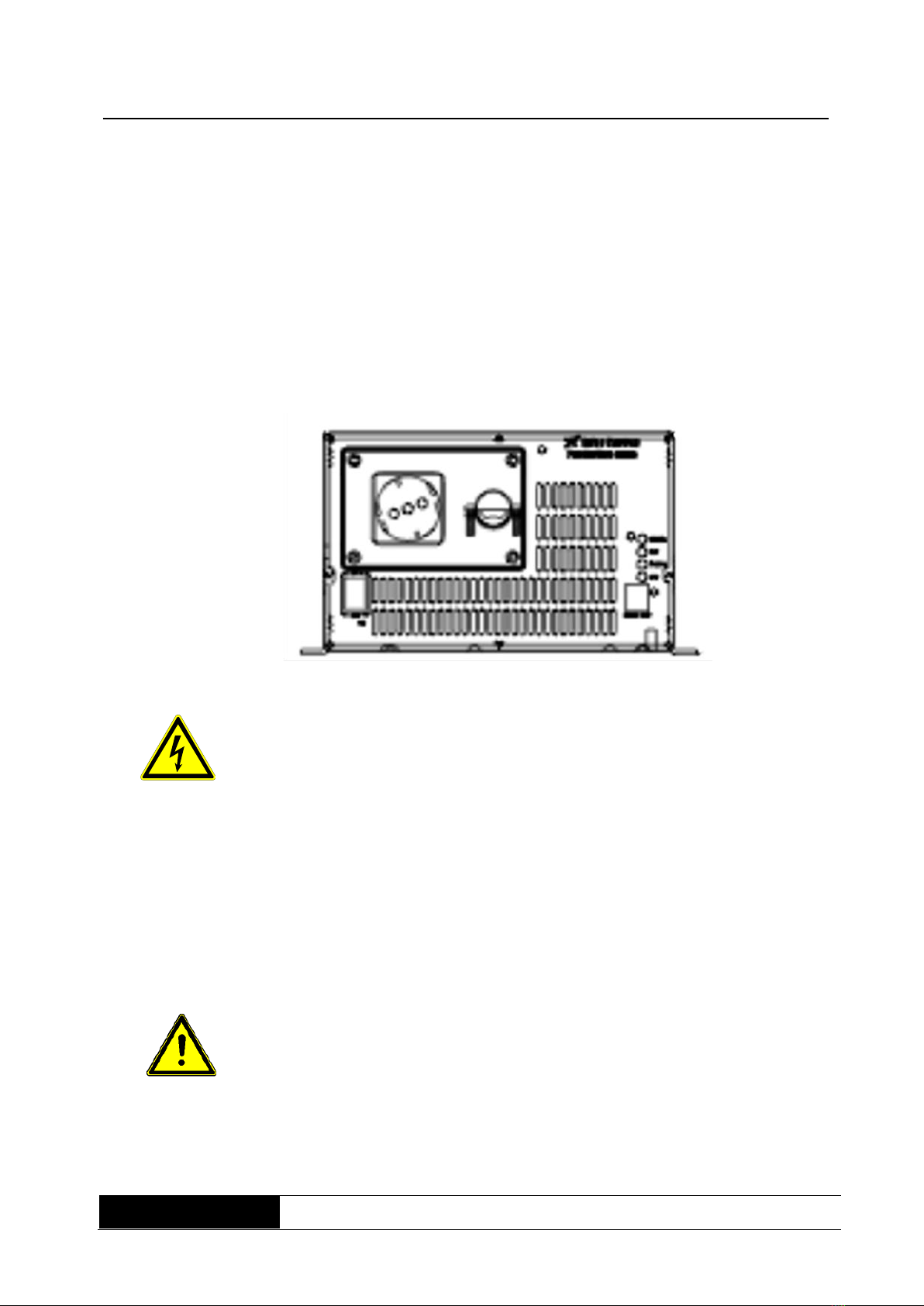
5.1 Display and handling elements on the front side
All handling and display elements, which are necessary for normal service, are
on the front side.
Fig. 1:
front side view WRSL
3000
Danger !
On the output socket is dangerous voltage.
Danger !
The terminal cover may only be opened when the battery connection is
disconnected. The connection to the terminal strip must only be carried out
by authorised specialist personnel.
5.1.1 Handling elements of the inverter
ON / OFF switch:
POWER-switch ON/OFF is switching-on or switching-off the control circuit.
During installation let the switch OFF.
DIP switch:
By the DIP switch, you can select the output frequency 50Hz or 60Hz.
Never change the settings during operation.

SINE WAVE INVERTER WRSL-xx-3000 Manual
WRSL series
page 13 of 32
5.1.2 Display elements of the inverter
Generally the display elements are first active, when the inverter is
switched-on (ON).
Status - LED:
The Status –LED´s indicated the condition from Inverter.
RJ45 socket (REMOTE PORT)
On remote control (additional accessory) to query the operating status or to
control it with the remote control.
Usage of the optional remote control:
A: LOCK
B: UNLOCK
C: POWER ON INDICATOR
D: ON/OFF BUTTON
E: REMOTE OPERATION SOCKET
(connection socket for the cable)
SINE WAVE INVERTER WRSL-xx-3000 Manual
WRSL series
page 14 of 32
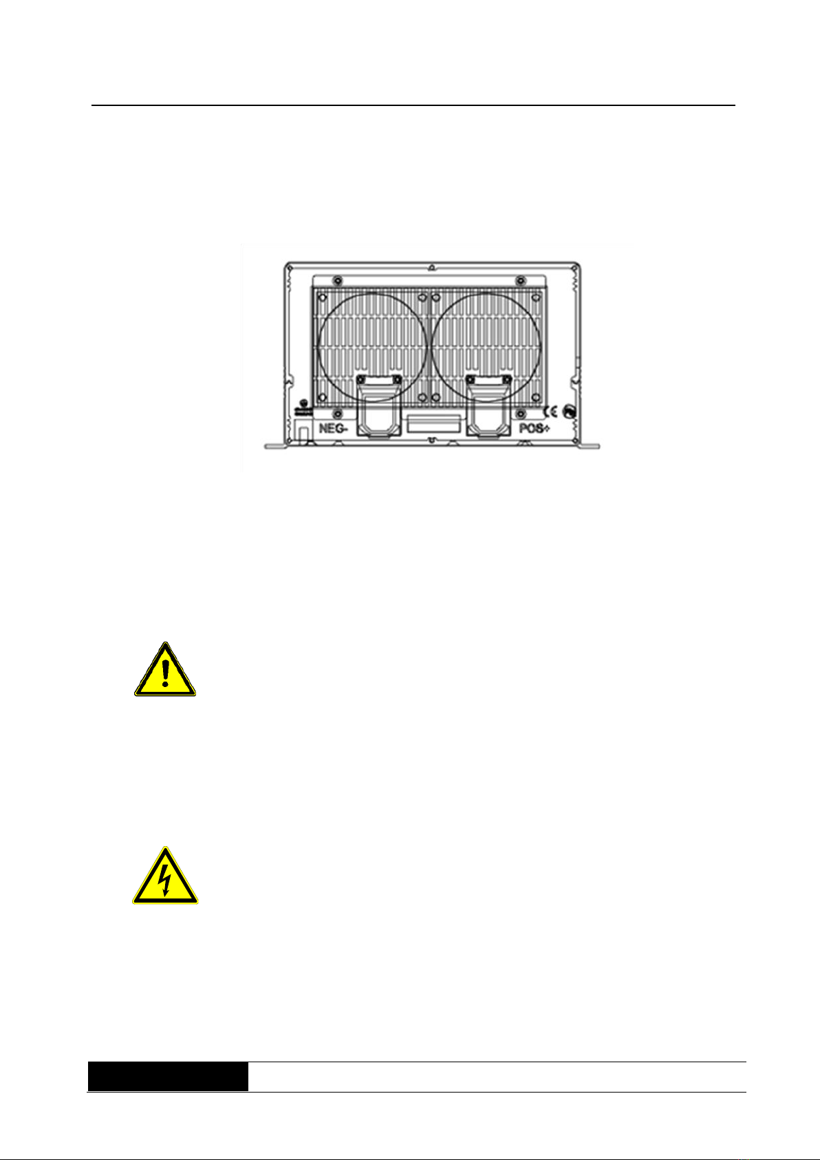
5.2 Elements on the back side
Fig.. 2:
back side view WRSL
3000
Battery terminal
blocks:
Connect 12V / 24V / 48V batteries, or others, with 12V / 24V / 48V
energy sources.
+ is positive,- is negative. When wiring the internal fuse will blow and
can damage the inverter forever.
Always compare, bevore connecting, the indicated voltages of
the inverters and the battery.
The figures have to agree with each other.
E.g. do not connect the 12 V model to a 24 V battery, because then
the equipment will be destroyed immediately.
PE-connection:
Connect the PE-connection of the inverter with the grounding
point of the place of installation with an insolatied cable with a
minimum cross-section of 4mm2.
Do not use the inverter without a PE.
Then there is danger of electric shocks.

SINE WAVE INVERTER WRSL-xx-3000 Manual
WRSL series
page 15 of 32
Ventilation opening:
Keep a minimum distance of 10cm from the vents of the front side and
back side of the equipment to other objects, to avoid an air blockage
and an overheat. Ensure that the vents of the equipment are not
blocked, e.g by absorbed paper, tissue, etc.
5.3 Elements on the side panel
Identification label
on the bottom of the
inverter:
The identification label contains information about:
# manufacturer
# equipment model and power class
# equipment input values
# equipment output values
# CE- and barcode- designation
DIP switches: When the inverter is switched off, the basic parameters of the
inverter can be set.

SINE WAVE INVERTER WRSL-xx-3000 Manual
WRSL series
page 16 of 32
6 Storage and unpacking
6.1 Storage of the inverter
If the equipment is not installed immediately, the following should be observed:
The equipment and accessories must always be left and stored in the original packaging.
The recommended ambient storage temperatures are: +0°C...+40°C.
Protect the equipment and its packaging from moisture.
6.2 Unpacking the equipment
Remove the shipping cartons and packaging material.
Check the shipping note to make sure that the delivery is complete. If the
delivery is incomplete or incorrect, inform the supplier immediately.
You should also check the delivery for transport damage. Any claims for
transport damage must be made immediately:
Retain all shipping cartons and packaging material for verification purposes.
Immediately inform the manufacturer or your supplier.
Immediately inform the shipping company.

SINE WAVE INVERTER WRSL-xx-3000 Manual
WRSL series
page 17 of 32
7 Installation and connecting of the inverter
All requirements in the technical data regarding environmental and operating
conditions must be observed to ensure trouble-free functioning of the UPS.
The following must be observed when setting up / installing the SI:
Avoid extremes of temperature and atmospheric humidity
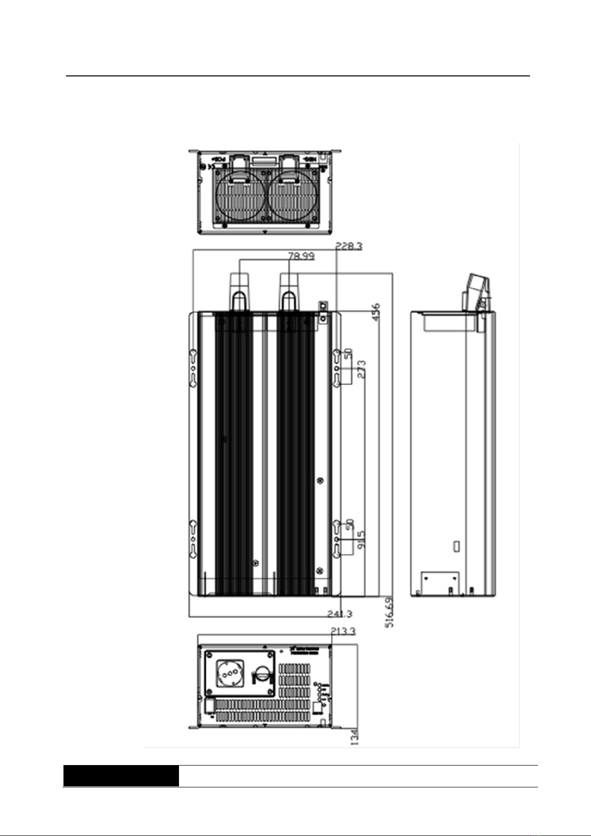
Observe the specified installation location and only mount the equipment using
the screw-in positions (fig. 4).
Make sure that ventilation of the equipment is possible at all times. Ensure an
appropriate flow channel.
Make sure the equipment is arranged correctly. When installed in parent
systems (e.g. machine, control cabinet), it must be ensured that the inverter
operates within the specified temperature range. A sufficient level of forced
ventilation must exist to remove excess heat that builds up in the space where
the SI is installed.
SINE WAVE INVERTER WRSL-xx-3000 Manual
WRSL series
page 18 of 32
a) WRSL-0xx-3000
Fig. 3: screw-in
positions and
external dimension

SINE WAVE INVERTER WRSL-xx-3000 Manual
WRSL series
page 19 of 32
7.1 Connecting the inverter
- Earth connection:
Connect the protective earth conductor PE of the inverter with
the grounding point of the place of installation, by using an
isolated line with a minimum cable cross-section of 10qmm2.
Ensure that the connections are fixed and safe, the lines have
to be laid in one piece and must not be extended!
Depending on place of installation as a precaution the inverter
has to be grounded. In a car this can be the bodywork, in a
boat the grounding system of the boat or in case of a building
the earth electrode of the building. In case of a stationary
installation, e.g. camping ground, the grounding has to be
made by an at least 1.2m earth electrode, which must be in the
ground.
- AC outlet sockets:
The consumer can either be plugged into the earthed socket or
connected directly to the terminal strip (behind the terminal
cover plate Fig.4).
Avoid overload of the inverter.
If you connect more consumer with the inverter, connect them
sequentially after having switched-on the inverter.
Before connecting, compare always the indicated voltage
figures of the consumers with the output voltage of the
inverter. Those figures have to comply.
E.g. do not connect the 115V consumer with a 230V inverter,
because then the equipment will be destroyed immediately.
Danger !
There are dangerously high voltages at the output plug and the
terminal strip.
Earthed socket outlet 16A

SINE WAVE INVERTER WRSL-xx-3000 Manual
WRSL series
page 20 of 32
Fig. 4:
terminal connection
Danger !
The terminal cover may only be opened when the battery connection is
disconnected. The connection to the terminal strip must only be carried out by
authorised specialist personnel.
Work steps for terminal connection:
1. disconnect the battery.
2. unscrew terminal cover (4 screws).
3. lead the cable through the cable gland.
4. screw on the wires with the correct polarity.
5. screw on the strain relief.
6. screw on terminal cover again.
This manual suits for next models
2
Table of contents
Other Effekta Inverter manuals


Popular Inverter manuals by other brands


EURA DRIVES
EURA DRIVES EM30 Series Safety instructions, Installation & operating manual

SolarTorrent
SolarTorrent 1000W Grid Tie Power Inverter user guide

Growatt
Growatt SPI 3000 user manual

CE+T Power
CE+T Power Bravo 10 - 48/230 user manual

Fischer Panda
Fischer Panda Panda AGT/DC 10000 PMS Operation manual

Maxeon
Maxeon Sunpower Important Safety and Installation Instructions