Effort International TX3000 User manual

1
RF SYSTEM(RS009)Manual
TX3000
TUNING GUIDE

2
Contents
Chapter 1 Introduction ...................................................................................................................3
1.1. Basic Description of the Transmitter Electronics...............................................................3
1.1.1. Digital Part ..............................................................................................................7
1.1.2. Analog Part..............................................................................................................7
1.1.3. Power Supply / Filter Part.......................................................................................7
1.2. Receiver Electronics ..........................................................................................................8
Chapter 2 RX3000 Filter Concept..................................................................................................8
Chapter 3 TX3000Cable\Opto Synchronization Setting ................................................................ 9
3.1. TX3000 cable synchronization setting...............................................................................9
3.2. TX3000 Opto Synchronization Setting ............................................................................14
Chapter 4 Tuning..........................................................................................................................19
4.1. One (1) Opto TX Output ..................................................................................................19
4.2. Preparation .......................................................................................................................19
4.3. Power On Adjustments.....................................................................................................20
Chapter 5 Appendix .............................................................................................................22
5.1. TX3000 Board..................................................................................................................22

3
5.2. Socket Specifications .......................................................................................................22
Chapter 1
Introduction
This manual describes the TX3000 as well as the setup and tuning procedures needed to
put the TX3000 and RX3000 electronics into operation. For details on the receiver board,
see the RX 3000 Tuning Guide.
1.1. Basic Description of the Transmitter Electronics
Each transmitter electronic is able to feed one OEA antenna with a swept HF signal of 8.2
MHz. In order to avoid disturbances between the emitted HF signals, synchronization
with other transmitters must be guaranteed.

4
The standard version of the TX3000 board allows the 82Hz sinusoidal modulated 8.2
MHz HF carrier signal to be:
−generated locally (oscillator circuit for master applications), or alternatively.
−to be regenerated from an optically received swept HF signal of another
TX3000 (opto receiver for slave applications).
The bi-opto version of the TX3000 additionally allows the onboard generated (master) or
received-and-then-regenerated- (slave)-swept HF-signal to be converted and optically
transmitted in order to synchronize additional transmitters.
The two opto transmitters used in the bi-opto version allow:
−a master transmitter to synchronize two other optically slaved (and possibly
repeating) transmitters.
−an optically slaved transmitter to be used as repeater to synchronize two other
optically slaved transmitters.
By using 3 bi-opto transmitter boards (TX3000) (one used as synchronization master and
two as synchronization repeaters) and 4 standard TX3000 (as synchronization slaves),
clusters of up to 7 TX3000 may be synchronized. This way up to 7 checkout or 14
exit-gates (in a row) may be configured without need of a master rack.
Since the optically transmitted synchronization signal may be repeated only once, a
master rack still has to be used if more than seven transmitters have to be synchronized.
The cable version of the TX3000 additionally allows the onboard generated (master) or
received-and-then-regenerated- (slave)-swept HF-signal to be converted and optically
transmitted in order to synchronize additional transmitters.
The two cable transmitters used in the cable version allow:
−a master transmitter to synchronize, a other optically slaved (and possibly
repeating) transmitters.
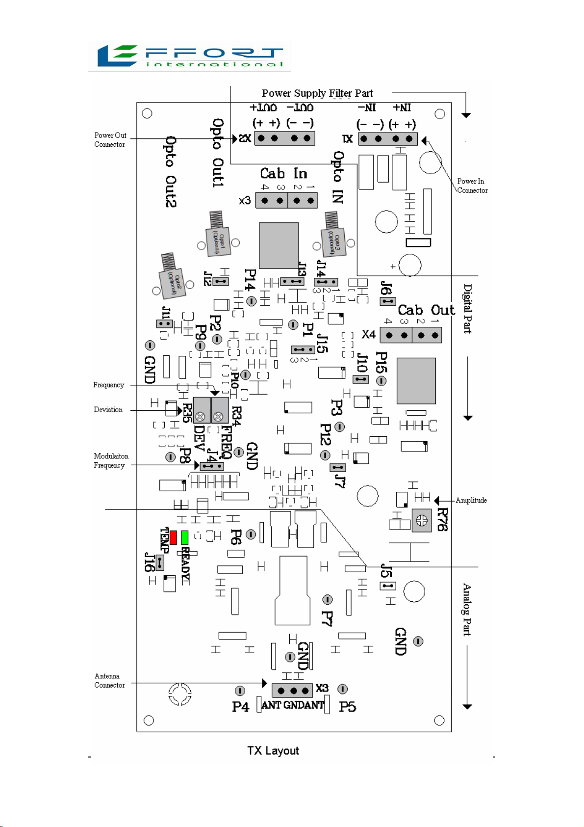
Two block diagrams and layout of the TX3000 board are shown on the next 2 pages.
The board consists of a digital part,an analog part and a power supply/filter part.
The standard version of the TX3000 is fully equipped with the exception of the two
optional opto transmitters. It can be used as a master-TX3000 for small installations
(single or dual gates equipped with one TX3000 only) or as slave-TX3000 for all larger
applications.
The bi-opto version of the TX3000 board is almost identical to the standard version. The
only difference is that the two opto transmitters (IR-LED's) are already mounted. The
bi-opto TX3000 board can be used as a Master-TX3000 in medium installations (2 to 7
TX3000) or as synchronization signal repeating Slave-TX3000 for medium to very large
installations.

5
6

7
1.1.1. Digital Part
In master operation, the 82Hz sinusoidal sweep is fed to the voltage controlled oscillator
(VCO). The VCO generates the swept and digitalized 8.2MHz signal. This frequency
modulated signal is digitally amplified (FET power amplifier), filtered to get a clean
analog output signal and finally radiated by the antenna. If the current exceeds the
allowed limit (short circuits, wrong antenna etc.) the power amplifier will shut slowly
down, because it is temperature controlled. This action is indicated by a red LED
(overloaded = OFF).
In slave operation, the swept HF signal is optically received, converted and regenerated. It
can then be used to directly feed the power amplifier. A set of jumpers (J14 and J15) is
used to switch between master and slave operation. Jumper J4 is used to select the desired
sweep frequency.
If the board is equipped with two opto transmitters (bi-opto TX3000 board), the swept HF
signal will be automatically output (see section 4). This allows the synchronization of two
additional transmitters.
1.1.2. Analog Part
Different antenna types can to be connected to the relevant output circuit (connector X4).
The TX3000-mounted matching circuits and harmonic suppression filters are optimized
for use with 200 Ohm antennas.
The TX3000 is not designed to drive other types of antennas. All equipment
and system guarantees will be lost and all field support will be charged if other types of
antennas are used without our written approval of OEA.
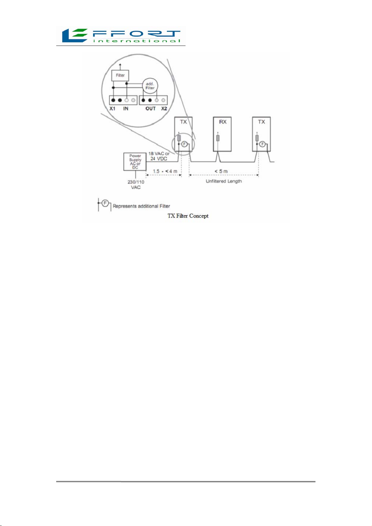
1.1.3. Power Supply / Filter Part
The TX3000 can be powered (connector X1/IN) by DC as well as AC power supplies.
The integrated power line filters:
−suppress noise between the electronics and the power line
−suppress conducted noise on the power line itself.
The filtered power is available at connector X2/OUT and can be used to feed other
equipment(TX3000, RX3000). For additional information, see section 2, TX3000 Filter

8
Concept.
1.2. Receiver Electronics
For detailed information on the receiver, see RX 3000 Tuning Guide.
Chapter 2
RX3000 Filter Concept
False alarms due to conducted noise on the power lines can be avoided if the power lines
are filtered every 4 to 6 meters.
If TX3000’s are used, this is done automatically and the power line between the
transmitters is not longer than 6 (8.2MHz) meters. If the length of the power cable
between the transmitters is longer than 4 to 6 meters, additional filter boards have to be
use. RX3000 boards use the same kind of filter. Due to the limited space available,
however, the RX3000 filter only protects the receiver electronics itself, it doesn't
contribute to the filtering of the power line.
9
Chapter 3
TX3000Cable\Opto Synchronization Setting
3.1. TX3000 cable synchronization setting
On the TX3000 are two optional Wire Cable Sockets,one is Cable In and the other is
Cable Out.
3.1.1. TX3000 cable synchronization output setting (master)
•J15 must be 2-3 IN
•must be connect by twisted-pair
The system can provide two sets of cable out.On the board of TX3000,it is annotated as
X4(Cab Out), N0. 1 and 2 of X4 is the first group ,and N0. 3 and 4 is the second
group.The setting of one group sync output is same to the two groups sync output(refer to
the above).Each cable out should connect to the corresponding sockets. E.g. If you use the
first group of cable ,you should connect to the N0.1 and 2 sockets of X4(refer to the
figure of TX layout 1).

10
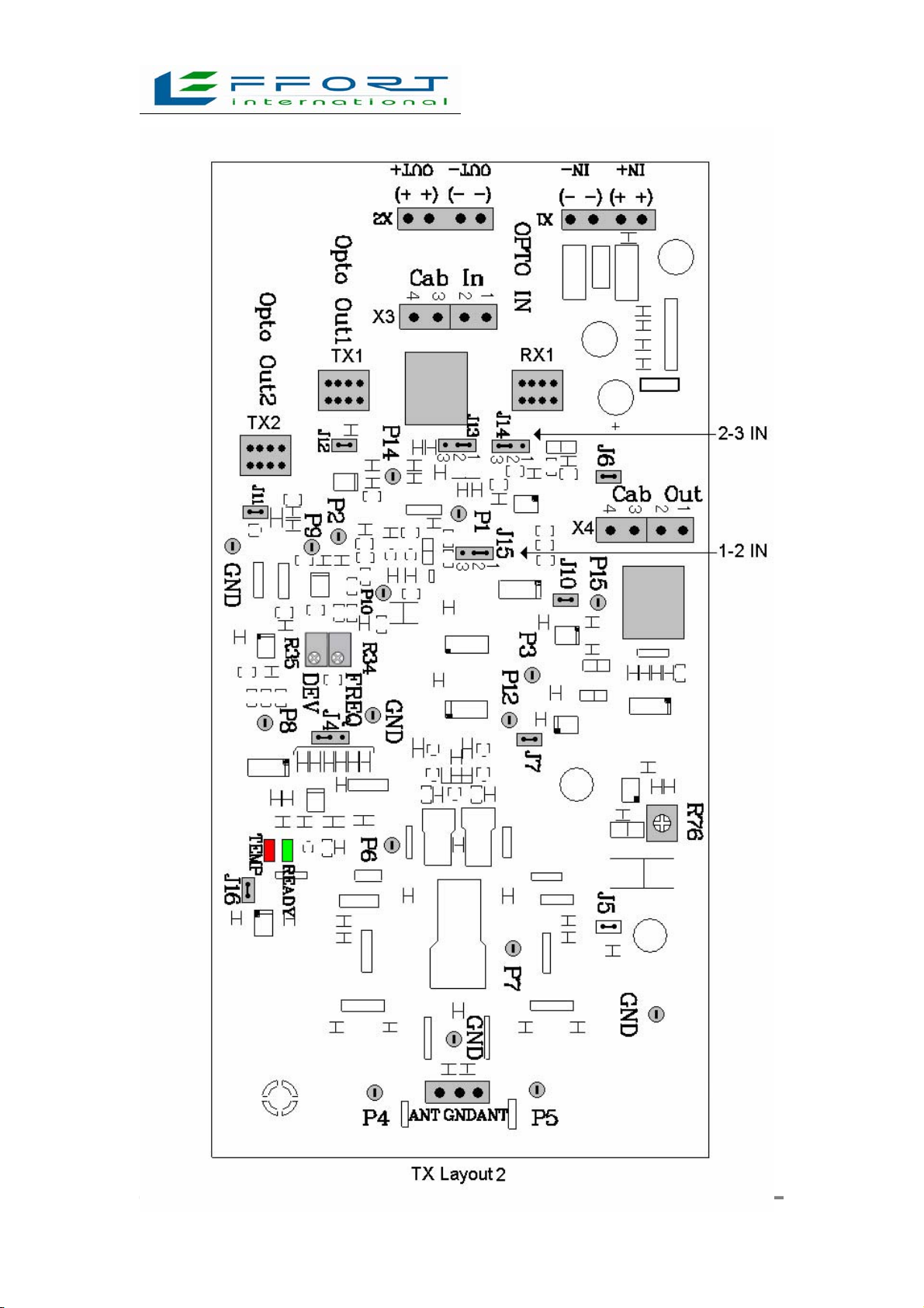
3.1.2. TX3000 Cable Synchronization Input setting (slave)
•J14 must be 2-3 IN
•J15 must be 1-2 IN
•must be connect by twisted-pair
The system can provide two sets of cable in.On the board of TX3000,it is annotated as
X3(Cab In), N0. 1 and 2 of X3 is the first group ,and N0. 3 and 4 is the second group.You
only need one group in actual use.Each cable in should connect to the corresponding
sockets. E.g. If you use the first group of cable, you should connect the N0.1 and 2
sockets of X3(refer to the figure of TX layout 2).

11
12

13
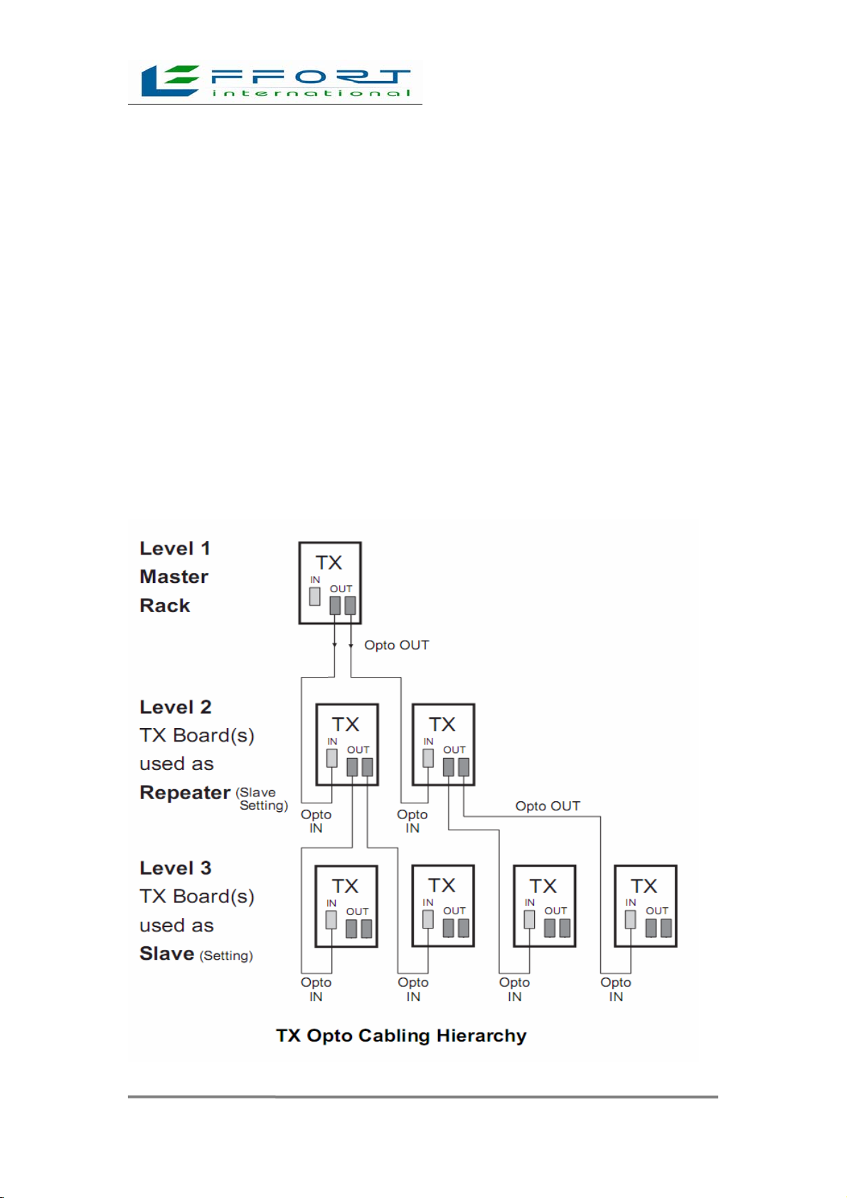
3.1.3. TX3000 Cable Synchronization Setup Rule
Since the TX3000 can be used as a synchronization master, repeater or slave, installations
can be flexibly configured.
The optically transmitted synchronization signal may be repeated only once; therefore no
synchronization repeater should ever feed another repeater if there has no master. The
TX3000 board of level 1 (bi-opto version, configured as master) feeds the
synchronization signal to the two TX3000 boards of level 2 (bi-opto version, configured
as slave). The TX3000 board of level 2 can also feeds the synchronization signal of the
level 1 to the TX3000 boards of level 3.
A basic configuration following this rule is shown below:
If a system consists of more than seven transmitters, a master rack has to be used as a
synchronization source.

14
3.2. TX3000 Opto Synchronization Setting
On the TX3000 board are two Opto synchronization output sockets and one Opto
synchronization input socket.Synchronization output sockets are TX1(Opto Out1) and
TX2(Opto Out2);Synchronization input socket is RX1(Opto In).
3.2.1. TX3000 Opto Synchronization Output Setting (master )
• J15 must be 2-3 IN (refer to the figure of TX Layout3);
• Optical fiber transmitter use HFBR-14X4 series,Optical jumper socket is
ST,and 62.5/125µm multimode fibre;
•The system provide two Opto output,TX1 is the first output socket(Opto Out1),
TX2 is the second output socket(Opto Out2).The connection mode of the Optical fiber
transmitter to socket refers to the figure of TX Layout 1.
•If you use only one Opto synchronization output,you must use TX1output(Opto
Out1),and J11 should be IN.Or it will fail.
•If you use two Opto synchronization outputs,J11 should be OUT. Or it can not
achieve the second synchronization(Opto Out2).
•E.g. If connect TX1 and TX2 refer to the figure TX Layout 1,J11 is OUT and
J15 is 2-3IN,it can achieve two ways Opto synchronization output.
3.2.2. TX3000 Opto synchronization Input Setting (slave)
•J14 must be 1-2 IN
•J15 must be 1-2 IN
•Optical fiber receiver use HFBR-24X6 series,Optical jumper receiver
specification is same to the optiacal fiber transmitter.
The system's optical input is RX1(Opto In),insert optical receiver in RX1,J14 must be 1-2
IN,J15 must be 1-2 IN,so it can achieve Opto synchronization input.
Please refer to figure TX Layout 4:

15

16
17
3.2.3. TX3000 Opto Synchronization Setting rule
Since the TX3000 can be used as a synchronization master, repeater or slave, installations
can be flexibly configured. Basically there exists only one rule that has to be considered:
The optically transmitted synchronization signal may be repeated only once, therefore no
synchronization repeater should ever feed another repeater.
A basic configuration following this rule is shown below. The TX3000 board of level 1
(bi-opto version, configured as master) feeds the synchronization signal to the two
TX3000 boards of level 2 (bi-opto version, configured as slave). These two boards, acting
as synchronization repeaters, in turn each feed their optically transmitted signal to two
following TX3000 boards of level 3 (standard version, configured as slave). This way, a
synchronization cluster of 7 transmitters has been created without use of a master rack. If
a system consists of more than seven transmitters, a master rack has to be used as a
synchronization source.
18
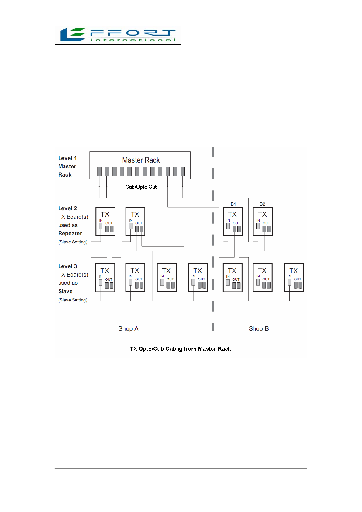
3.3 TX3000 Opto/cab Cablig from Master Rack
If a system consists of more than seven transmitters, a master rack has to be used
as a synchronization source.
A possible configuration using a master rack and TX3000 is shown below.
19
Chapter 4
Tuning
Step-by-step instructions for tuning the TX3000 board follow. For the receiver see
RX 3000 Tuning Guide.
4.1. One (1) Opto TX Output
The following instruments are recommended for tuning:
−Battery powered oscilloscope (two channels, cursor readout function
recommended).
−10: 1 oscilloscope probe.
−Multimeter.
4.2. Preparation
• Power OFF the TX3000 board (remove PWR connector at socket X1).
• Ensure that the antenna is connected to the correct socket (X5) on the TX3000
board.
• Turn the amplitude potentiometer R76 (LVL to almost (7/8) full power clockwise).
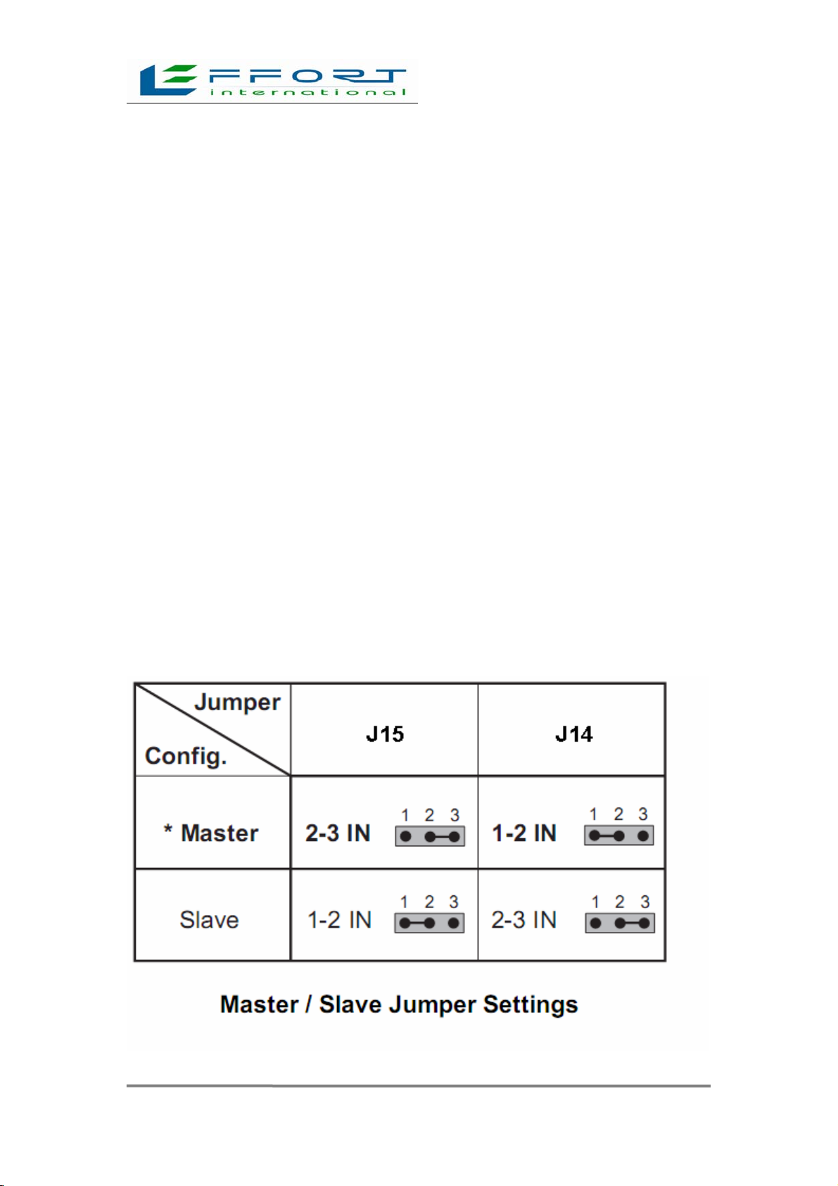
• Check the default setting of jumper J15 to J14 (see following the table).

20
* Factory default setting
4.3. Power On Adjustments
• Power ON the TX3000 board (insert PWR connector at socket X1).
• Check the red Temp-Limit LED is ON: Operation OK.
• If the LED is going OFF and ON:
−reduce the emitted power with the amplitude potentiometer R76.
−exchange TX3000 board.
−check antenna, matching board for short circuit and so on.
• As an option, check the emitted signal at both of the corresponding test points located to
the left and right of the antenna connector (P4/GND and P5/GND; see TX Layout5). The
signal shapes may be varying. A signal breakdown or variation of more than 20% of
average the value indicates a faulty transmitter or antenna.
Remark: The signal on P4 and P5 is usually not identical.
• Proceed with the RX3000cording to the instructions in the RX3000 Tuning Guide.
Hints: If the HF power received at the RX3000 is too high:
−insert the "Narrow" jumper on the RX3000 board.
−reduce the TX3000 power.
This manual suits for next models
1
Table of contents


