Renishaw OMM Setup guide

Repair instructions
H-2000-4042-03-A
OMM and OMME
Fitting a new printed circuit board to a
Renishaw Optical Module Machine

© 1999-2009 Renishaw plc. All rights reserved.
This document may not be copied or reproduced in whole or in part, or
transferred to any other media or language, by any means, without the
prior written permission of Renishaw.
The publication of material within this document does not imply freedom
from the patent rights of Renishaw plc.
Disclaimer
RENISHAW HAS MADE CONSIDERABLE EFFORTS TO ENSURE
THE CONTENT OF THIS DOCUMENT IS CORRECT AT THE DATE OF
PUBLICATION BUT MAKES NO WARRANTIES OR REPRESENTATIONS
REGARDING THE CONTENT. RENISHAW EXCLUDES LIABILITY,
HOWSOEVER ARISING, FOR ANY INACCURACIES IN THIS
DOCUMENT.
Trademarks
RENISHAW® and the probe emblem used in the RENISHAW logo are
registered trademarks of Renishaw plc in the UK and other countries.
apply innovation is a trademark of Renishaw plc.
All other brand names and product names used in this document are
trade names, service marks, trademarks, or registered trademarks of their
respective owners.
Renishaw part no: H-2000-4042-03-A
Issued: 02.2009
1
!
Introduction
The repair instructions contained within this publication provide
detailed, step-by-step instructions for replacing a defective printed
circuit board (PCB) contained within the following range of Renishaw
Optical Module Machines:
Product description Part number
OMM A-2033-0576
OMME A-2033-7268
Prior to carrying out the instructions contained within this publication,
it is important to ensure that you have the correct PCB assembly kit for
your product as listed below:
Product description Part number of PCB assembly kit
OMM A-2031-0043
OMME A-2031-0201
WARNING: Prior to carrying out the procedures detailed in
this publication, it is important to ensure that you switch off the
power to the OMM.

2
Replacing the defective PCB
Removing the window and label from the OMM
CAUTION: The following procedures must be carried out in a
clean environment. Do not allow liquids or solid particles to
enter the OMM body. Never remove the window by twisting or rotating
by hand. Always use the jacking screws provided.
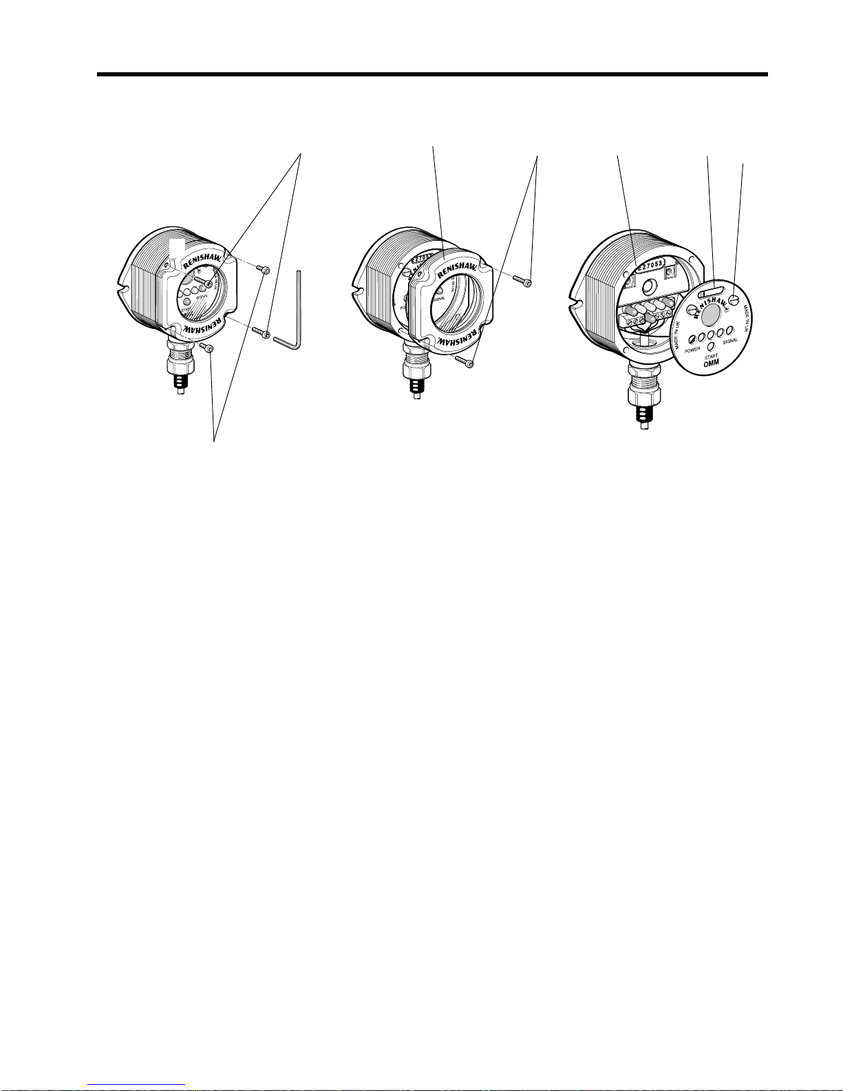
To remove the window and label from the OMM, carry out the following
(see Figure 1):
1. Using a 2.5 mm AF allen key, release and remove the two short
screws [1] and the two long screws [2] securing the window [3]
to the OMM body [4].
2. Re-insert the two long screws [2] into the two threaded holes A.
3. Tighten, in turn, the two long screws [2] to evenly and carefully
jack the window [3] from the OMM body [4]. Gently remove the
window from the OMM body.
4. Release the label [6] from the OMM body [4] by turning the
two quick release screws [5] a quarter turn counterclockwise.
Carefully lift the label from the OMM body to gain access to the
defective PCB.
!
3
1. Screw (short) (2 off)
2. Screw (long) (2 off)
3. Window
4. OMM body
5. Quick release screw (2 off)
6. Label
Figure 1 – Removal of the OMM window and label
2
1
A
B
A
2
3
A
45
6
A
B
4
Replacing the defective PCB within the OMM body
To replace the defective PCB within the OMM body, carry out the
following (see Figures 2 and 3):
1. Disconnect the wires from the terminal block.
2. Pull gently on the wire handle attached to the PCB and carefully
remove the PCB from the OMM body.
3. Referring to Figure 3, note the switch settings of the OMM
range selection switch on the PCB so that these can be
duplicated when fitting the new, replacement PCB.
4. Referring to Figure 2, carefully inspect the PCB supports for
signs of damage; if damage is evident then return the complete
OMM to Renishaw for repair.
5. Obtain the relevant PCB assembly kit for the type of OMM on
which you are carrying out the repair:
Product description Part number of PCB assembly kit
OMM A-2031-0043
OMME A-2031-0201
6. If necessary, adjust the settings of the OMM range selection
switch to those noted during step 3.
7. Carefully assemble the new PCB to the OMM body and,
referring to Figure 2, connect the wires to the terminal block
of the new PCB.Torque-tighten each terminal block screw to
between 0.25 Nm and 0.4 Nm (0.18 lbf.in. and 0.29 lbf.in.).

5
Figure 2 – Replacing the OMM printed circuit board
Figure 3 – OMM range selection switch
Wire handle
PCB
support
On
Off
Screen
Green/yellow
Green
Brown
PCB
White Grey
Yellow

6
Replacing the OMM label and window
To replace the OMM label and window, carry out the following (see
Figure 4):
1. Refer to View A and assemble the new label [1] supplied and
secure with the two quick release screws [2]. Rotate the screws
a quarter turn clockwise to hold the label in place.
2. Remove the existing ‘O’ring [5] and visually examine the OMM
body [3] for damage or scratching to the‘O’ ring location groove
as shown in View A.If no damage is found, then fit the new‘O’
ring supplied.
3. Visually examine the window [4] and‘O’ring [5] for cleanliness
as shown in View B. Also ensure that both the window and ‘O’
ring are undamaged.
4. Refer to View C and insert the two short screws [6] into the two
threaded holes A in the window [4].Tighten the two screws to
0.3 Nm to 0.5 Nm (0.22 lbf.ft to 0.37 lbf.ft).
5. Lightly smear the ‘O’ ring [5] with silicone grease and assemble
the window [4] to the OMM body [3].
6. Insert the two long screws [7] into the two plain holes B.Tighten
each screw a few turns at a time to gradually pull the window
[4] evenly against the OMM body [3].There may be some
resistance due to the compression of air trapped inside the
OMM body.
7. Tighten the screws [7] in turn, to pull the window [4] evenly into
the body of the OMM. Finally tighten the screws to 0.9 Nm to
1.1 Nm (0.66 lbf.ft to 0.81 lbf.ft).

7
1. Label
2. Retaining screw (2 off)
3. OMM body
4. Window
5. ‘O’ring
6. Screw (short) (2 off)
7. Screw (long) (2 off)
Figure 4 – Replacing the OMM label and window
32
1
4
56
7
4
3
A
A
B
B
Ensure that the window
and ‘O’ ring are clean
and undamaged
Inspect the ‘O’ ring
location groove for
damage

Other manuals for OMM
1
This manual suits for next models
1
Table of contents
Other Renishaw Receiver manuals


