EG&G ORTEC 402A Service manual
J
fgAj
n
^Ik}
o%
Models
402A
and
402D
Power
Supplies
Operating
and
Service
Manual

Models
402A
and
402D
Power
Supplies
Operating
and
Service
Manual
This
manual
applies
to
instruments
marked
402A
"Rev
47"
on
rear
panel
402D
"Rev
29"
on
rear
panel
3235
5.0C
0482
Printed
in
U.S.A.
STANDARD
WARRANTY
FOR
EG&G
ORTEC
INSTRUMENTS
EG&G
ORTEC
warrants
that
the
items
will
be
delivered
free
from
defects
in
material
or
workmanship.
EG&G
ORTEC
makes
no
other
warranties,
express
or
implied,
and
specifically
NO
WARRANTY
OF
MERCHANTABILITY
OR
FITNESS
FOR
A
PARTICULAR
PURPOSE.
EG&G
ORTEC's
exclusive
liability
is
limited
to
repairing
or
replacing
at
EG&G
ORTEC's
option,
items
found
by
EG&G
ORTEC
to
be
defective
in
workmanship
or
materials
within
one
year
from
the
date
of
delivery.
EG&G
ORTEC's
liability
on
any
claim
of
any
kind,
including
negligence,
loss
or
damages
arising
out
of,
connected
with,
or
from
the
performance
or
breach
thereof,
or
from
the
manufacture,
sale,
delivery,
resale,
repair,
or
use
of
any
item
or
services
covered
by
this
agree
ment
or
purchase
order,
shall
in
no
case
exceed
the
price
allocable
to
the
item
or
service
furnished
or
any
part
thereof
that
gives
rise
to
the
claim.
In
the
event
EG&G
ORTEC
fails
to
manufacture
or
deliver
items
called
for
in
this
agreement
or
purchase
order,
EG&G
ORTEC's
exclusive
liability
and
buyer's
exclusive
remedy
shall
be
release
of
the
buyer
from
the
obligation
to
pay
the
purchase
price.
In
no
event
shall
EG&G
ORTEC
be
liable
for
special
or
consequential
damages.
QUALITY
CONTROL
Before
being
approved
for
shipment,
each
EG&G
ORTEC
instrument
must
pass
a
stringent
set
of
quality
control
tests
designed
to
expose
any
flaws
in
materials
or
workmanship.
Permanent
records
of
these
tests
are
maintained
for
use
in
warranty
repair
and
as
a
source
of
statistical
information
for
design
improvements.
REPAIR
SERVICE
If
it
becomes
necessary
to
return
this
instrument
for
repair,
it
is
essential
that
Customer
Services
be
contacted
in
advance
of
its
return
so
that
a
Return
Authorization
Number
can
be
assigned
to
the
unit.
Also,
EG&G
ORTEC
must
be
informed,
either
in
writing
or
by
telephone
[(615)
482-4411),
of
the
nature
of
the
fault
of
the
instrument
being
returned
and
of
the
model,
serial,
and
revision
("Rev"
on
rear
panel)
numbers.
Failure
to
do
so
may
cause
unnecessary
delays
in
getting
the
unit
repaired.
The
EG&G
ORTEC
standard
procedure
requires
that
instruments
returned
for
repair
pass
the
same
quality
control
tests
that
are
used
for
new-production
instruments.
Instruments
that
are
returned
should
be
packed
so
that
they
will
withstand
normal
transit
handling
and
must
be
shipped
PREPAID
via
Air
Parcel
Post
or
United
Parcel
Service
to
the
nearest
EG&G
ORTEC
repair
center.
The
address
label
and
the
package
should
include
the
Return
Authorization
Number
assigned.
Instruments
being
returned
that
are
damaged
in
transit
due
to
inadequate
packing
will
be
repaired
at
the
sender's
expense,
and
it
will
be
the
sender's
responsibility
to
make
claim
with
the
shipper.
Instruments
not
in
warranty
will
be
repaired
at
the
standard
charge
unless
they
have
been
grossly
misused
or
mishandled,
in
which
case
the
user
will
be
notified
prior
to
the
repair
being
done.
A
quotation
will
be
sent
with
the
notification.
DAMAGE
IN
TRANSIT
Shipments
should
be
examined
immediately
upon
receipt
for
evidence
of external
or
concealed
damage.
The
carrier
making
delivery
should
be
notified
immediately
of
any
such
damage,
sihce
the
carrier
is
normally
liable
for
damage
in
shipment.
Packing
materials,
waybills,
and
other
such
documentation
should
be
preserved
in
order
to
establish
claims.
After
such
notification
to
the
carrier,
please
notify
EG&G
ORTEC
of
the
circumstances
so
that
assistance
can
be
provided
in
making
damage
claims
and
in
providing
replacement
equipment
if
necessary.
(^"^s^sji^^'^i^Ke*
''■ww
.
,'V'*4'j*
,'T-^yF«''*
,'
iti'f'-'^
sr.s^.
?'.'sE»'W^S^*a«^
'^V!T'tiicSSt!i'9^-fii!if'^^*'\'i>^^'*X''i
4:v4*nf
\4*'V•.•■•■
»,-/i*
»iV-iii^^-txS*.
«*-».
I«*V
j*i'-9<t'%iSr'>
/i*
•.i'"%"9-!4
^'*'7.
^■0,-
:
V,
iliPS^-:-:
-
i;^LS

EG&G
ORTEC
402A
POWER
SUPPLY
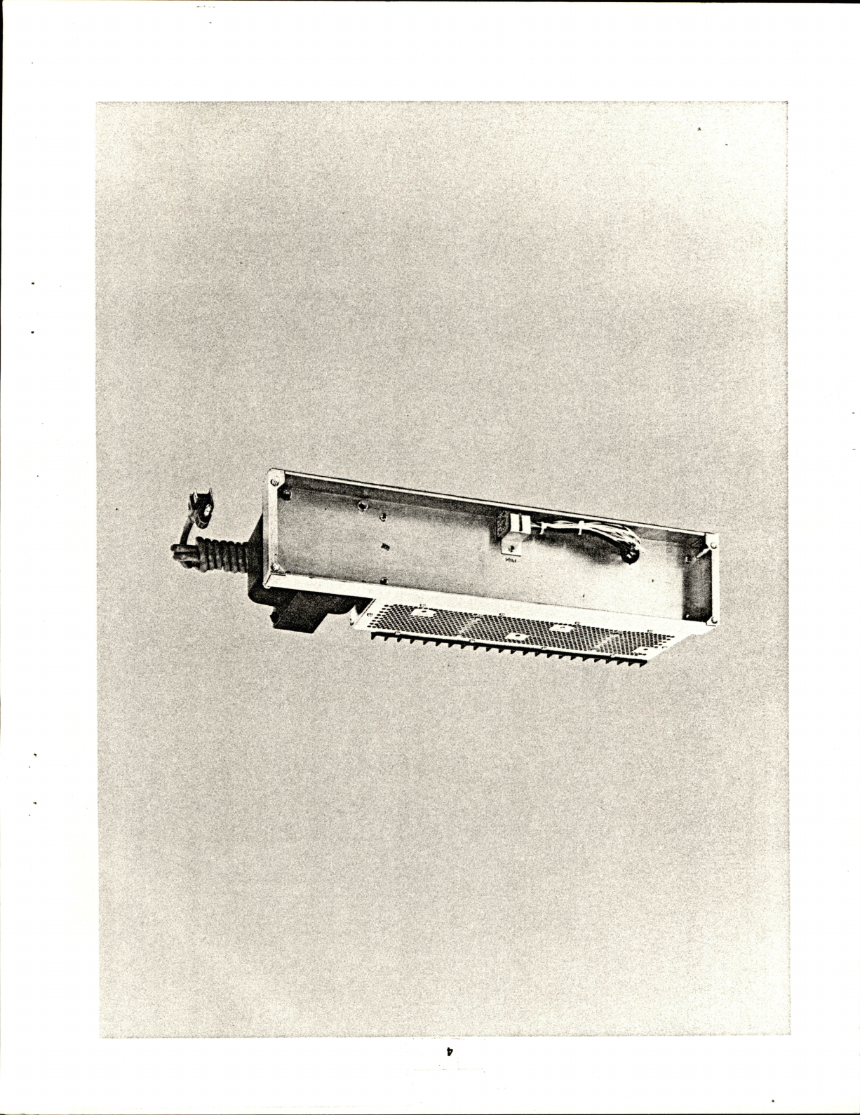
1.
DESCRIPTION
The
EG&G
ORTEC
402A
Power
Supply
is
designed
to
be
mounted
In
the
space
provided
on
the
rear
of
the
4001
A(B)
Modular
System
Bin.
The
Supply
was
designed
to
exceed
the
recommended
power
supply
specifications,
Appendix
A
of
TID-20893
(Rev),
Type
1,
Glass
A,
adopted
by
the
AEG
Committee
on
Nuclear
Instrument
Modules
(adopted
by
DOE).
The
402A
was
designed
for
both
foreign
and
domestic
usage.
Input
voltage
mains
of
117
V
ac
or
230
V
ac,
50-65
Hz,
may
be
used.
A
simple
circuit
modification
permits
operation
on
100-V
or200-V
input
mains
(see
Section
6).
A
convenience
indicating
switch
located
on
the
rear
of
the
Supply
clearly
identifies
the
intended
main
to
use.
The
primary
circuits
are
fused,
and
a
three-conductor
NEMA-standard
power
cord
is
included.
The
Supply
furnishes
four
standard
dc
voltages;
+12
V
at
2
A,
-12
V
at
2
A,
+24
V
at
1
A,
and
-24
V
at
1
A,
with
a
maximum
power
capability
of
72
W
at
50°G.
A
high-
efficiency
heat
sink
allows
additional
power
dissipation
(see
"Specifications").
The
dc
outputs
are
regulated,
short-circuit
protected,
current
limited,
and
thermal
protected.
The
117
V
ac
is
supplied
to
the
Bin
connector
independent
of
input
mains.
The
117-V
ac
power
available
is
limited
only
by
the
Power
Supply
fuse
when
operating
from
117-
V
ac
mains.
When
operating
from
230-V
ac
mains,
the
117-V
ac
is
derived
by
autotransformer
action
and
is
limited
to
50
VA
output
with
a
dc
load
on
the
power
supply
of
72
W.
A
control
panel
is
provided
on
the
4001
A(B)
Bin
for
oper
ating
and
monitoring
the
402A
Power
Supply.
An
On-Off
switch,
power
indicating
lamp,
thermal
warning
lamp,
and
convenience
dc
monitor
jacks
are
provided.
The
ther
mal
warning
lamp
Is
lighted
when
the
internal
tempera
ture
rises
to
within
20°G
of
the
maximum
safe
operating
temperature.
The
Power
Supply
Is
automatically
cut
off
by
an
internal
switch
should
the
temperature
exceed
the
maximum
safe
operating
temperature.
The
Power
Supply
regulator
amplifiers
are
located
on
the
two
identical
plug-in
printed
circuit
boards,
which
may
be
interchanged
for
maintenance
purposes.
Spare
regu
lator
boards
are
available.
The
regulating
transistors
and
current
monitoring
resistors
for
the
current
limiting
are
mounted
on
a
specially
designed
high-efficiency
heat
sink.
The
power
transistors
are
virtually
indestructible
due
to
their
power
handling
capability,
current
limiting,
and
short-circuit
protection.
Ail-silicon
semiconductors,
85°
G
capacitors
with
conservative
working
voltage
ratings,
and
high-quality
carbon
and
metal
film
resistors
are
com
bined
to
produce
this
Power
Supply
which
exceeds
the
TID-20893
(Rev)
requirements.
The
dc
output
voltages
are
adjustable
over
a
±1-V
range
from
their
nominal
ratings
through
holes
in
the
top
of
the
Power
Supply
cover
plate.
The
15-turn
adjustment
poten
tiometers
are
precision
cermet
for
superior
adjustment
resolution
and
resettabiiity
of
the
output
voltages.
2.
SPECIFICATIONS
The
specifications
for
the
402A
Power
Supply
meet
or
exceed
those
set
forth
by
the
AEG
Gommittee
on
Nuclear
Instrument
Modules,
TID-20893
(Rev),
Appendix
A,
Type
1,
Glass
A.
INPUT
103-129
V
ac,
50-65
Hz,
or
210-258
V
ac,
50-65
Hz.
Input
current
at
117
V
is
1.8
A
fora
72-W
dc
output.
DC
OUTPUT
Output
at
the
following
ratings
+12
V
at
2
A,
-12
V
at
2
A,
+24
V
at
1
A,
-24
V
at
1
A,
maximum
output
power
to
50°
G
ambient,
72
VA;
operation
to
60°
G
ambient
with
current
derated
not
more
than
3%/°G.
Under
certain
conditions
the
72-VA
power
limitation
may
be
exceeded
to
a
maximum
of
96
VA
(see
Fig.
2.1).
117
VOLT
AC
OUTPUT
117-V
ac
output
limited
only
by
the
supply
fuse
when
operating
from
117-V
ac
mains.
Output
is
limited
to
50
VA
at
72-VA
dc
load
while
operat
ing
from
230-V
ac
mains.
30*
C
60"
C*
130
260
120/240
>
110/220
100/200
20O464
'Ambient
Temp.
30
40
50
60
Total
dc
Load
(VA)
Fig.
2.1.
Maxltnuin
Sale
Operating
Range.
REGULATIONS
±0.05%
over
the
combined
range
of
zero
to
full
load
and
Input
voltage
of
103-129
V
ac
over
any
24-hr
period
at
a
constant
ambient
temperature
and
rated
line
and
load
after
a
60-mln
warmup.
STABILITY
±0.3%
after
a
24-hr
warmup
of
constant
line,
load,
and
ambient
temperature
over
a
six-month
period.
TEMPERATURE
COEFFICIENT
Less
than
0.01
%/°C
over
a
range
of
O^C
to
60°
C.
THERMAL
PROTECTION
A
thermal
warning
switch
will
be
activated
when
the
ambient
temperature
approaches
within
20°
C
of
the
safe
operating
temperature.
A
thermal
cutout
switch
disables
the
Power
Supply
when
the
tem
perature
exceeds
the
safe
operating
temperature.
NOISE
AND
RIPPLE
The
output
noise
and
ripple
are
less
than
3
mV
peak-to-peak,
as
observed
on
a
50-MHz
bandwidth
oscilloscope.
VOLTAGE
ADJUSTMENT
±0.5%
minimum
range,
reset-
tablllty
±0.05%
minimum
of
supply
voltage:
typical
±1
V
of
specified
voltage.
RECOVERY
TIME
Less
than
50
ns
to
return
to
within
±0.1%
of
rated
voltage
for
any
change
In
Input
voltage
and
load
current
from
10
to
100%
full
load.
CIRCUIT
PROTECTION
The
Input
line
to
the
power
supply
Is
fused.
In
addition,
electronic
circuitry
provides
output
current
limiting,
to
prevent
damage
to
the
supply,
and
provides
automatic
recovery
when
the
demand
Is
removed.
OUTPUT
IMPEDANCE
to
100
kHz.
Less
than
0.30
at
any
frequency
OUTPUT
CONNECTOR
All
power
and
control
circuits
terminate
In
a
connector,
specified
by
TID-20893
(Rev),
which
mates
with
the
Bin
Interface
connector,
complet
ing
the
necessary
control
and
Power
Supply
wiring.
DIMENSIONS
42.74
cm
(16.825
In.)
wide,
8.73
cm
(3.438
In.)
high,
13.97
cm
(
5.500
In.)
deep;
conforms
to
AEG
Drawing
ND515.
WEIGHT
Net
6
kg
(13
lb);
with
4001A(B),
12.5
kg
(27
lb).
Shipping
9
kg
(20
lb);
with
4001A(B),
16
kg
(35
lb).
3.
INSTALLATION
The
402A
Power
Supply
Is
normally
supplied
factory-
connected
to
an
EG&G
ORTEG
4001
A(B)
Modular
Sys
tem
Bin.
However,
the
supply
Is
designed
to
TID-20893
(Rev)
specifications
and
may
be
attached.
In
the
space
provided,
to
any
bin
manufactured
to
TID-20893
(Rev)
specifications.
For
attachment
to
other
than
an
EG&G
ORTEG
4001
A(B)
Bin,
please
refer
to
the
appropriate
Instruction
manual.
The
On-Off
switch
and
other
controls
necessary
to
oper
ate
the
Supply
are
part
of
the
Bin
and
not
furnished
with
the
Power
Supply.
For
attachment
to
a
4001
A(B)
Bin
the
following
steps
are
advised;
1.
Place
the
Bin
on
a
table
with
the
back
part
facing
you.
Place
the
Power
Supply
In
the
proper
mounting
position.
leaving
enough
space
between
the
two
pieces
to
attach
the
Interface
connector.
2.
Mate
the
Interface
connector,
being
careful
to
align
the
polarizing
pins.
Fold
and
form
all
wiring
close
to
the
connector
edges
to
prevent
any
wires
from
being
pinched
and
producing
a
short
circuit
In
succeeding
steps.
3.
Mount
the
Power
Supply
to
the
Bin
by
securely
tight
ening
the
four
10-32
screws,
being
careful
not
to
pinch
any
wires
or
to
use
undue
force
on
any
parts.
When
attaching
the
402A
Power
Supply
to
some
older
401
Bins,
It
Is
necessary
to
first
remove
the
left
and
right
side
covers
and
stand
the
Bin
on
Its
front
face
(handles
down).
From
this
point
on,
assembly
Is
the
same;
upon
comple
tion
the
side
plates
should
be
replaced.
4.
OPERATING
INSTRUCTIONS
The
available
current
from
the
Power
Supply
Is
specified
by
TID-20893
(Rev),
Appendix
A,
Type
1,
Glass
A,
supply.
Under
certain
conditions
these
specifications
may
be
exceeded
(see
Fig.
2.1).
Gare
must
be
used
to
ensure
natural
convection
of
heat
dissipated
by
the
heat
sinks
and
power
transformer.
For
best
results,
when
using
at
maximum
power
loadings
the
Bin
and
Power
Supply
should
be
In
an
open
space,
placed
upon
blocks
at
least
1
In.
off
the
table
mounting
surface
to
allow
maximum
venti
lation.
When
used
In
a
rack,
maximum
attention
should
be
paid
to
placement
of
other
heat-generating
equipment.
Adequate
unobstructed
space
on
all
sides
Is
necessary
for
convection
ventilation
and
cooling.
If
the
Bin
contains
other
heat-generating
equipment,
a
blower
may
be
advis
able
to
remove
the
dissipated
heat.

When
it
is
necessary
to
rack
mount
several
Bins
and
Power
Supplies,
especially
when
other
heat-generating
equipment
is
located
within
the
rack,
the
term
"ambient
temperature"
becomes
less
clearly
defined.
A
better
guide
to
maximum
power
loading
capability
is
to
monitor
the
heat
sink
temperature.
In
no
case
allow
the
heat
sink
temperature
to
continuously
run
above
85°
C.
Although
this
is
not
the
maximum
operation
temperature,
any
addi
tional
temperature
rise
due
to
other
conditions
of
the
sys
tem
may
force
the
Supply
out
of
tolerance
and
may
cause
it
to
automatically
shut
down
operation.
Should
your
operation
produce
a
temperature
of
85°
C,
a
blower
to
remove
the
dissipated
heat
is
recommended.
5.
CIRCUIT
DESCRIPTION
The
402A
Power
Supply
produces
four
dc
output
volt
ages.
A
power
transformer
transforms
the
input
ac
line
voltage
into
four
separate
low-voltage
sources.
The
sources
or
windings
are
full-wave-rectified,
capacitor-
filtered,
and
regulated
by
electronic
series
regulator
cir
cuits.
The
regulator
circuits
provide
short
circuit,
current
limiting,
and
reverse
current
protection.
Each
of
the
four
series
regulator
circuits
is
identical
in
operation:
they
are
physically
different
only
in
component
values
for
each
Supply.
The
regulator
essentially
operates
in
two
modes:
First
and
normal
is
the
voltage
regulation
mode:
second
is
the
constant-current
or
current-limiting
protection
mode.
The
regulation
will
operate
in
the
voltage
regulation
mode
at
any
current
output
up
to
and
including
the
full
rated
output
of
a
particular
supply.
When
current
output
beyond
the
rated
output
is
required,
which
includes
a
direct
short
across
the
output
terminals,
the
regulator
automatically
shifts
into
a
constant-current
mode.
This
provides
current
limiting
and
protection
of
the
regulator's
circuitry
and
components.
When
excessive
current
demands
are
re
moved,
the
regulator
resumes
the
voltage
regulation
mode.
For
operation
of
the
regulator,
please
refer
to
Circuit
Drawing
402A-1100-S1.
For
convenience,
only
the
+24-V
regulator
will
be
discussed,
and
the
following
is
an
explanation
of
the
regulation
in
the
normal
voltage
regu
lation
mode.
Transistors
Q6
and
Q7
operate
as
a
differential
amplifier
pair,
comparing
the
reference
voltage
of
04
at
the
base
of
Q6
with
a
portion
of
the
output
voltage
divided
down
through
R16, R17,
and
R18.
Trim
potentiometer
R17
is
used
to
adjust
the
output
voltage
to
the
specified
level.
A
difference
voltage
at
the
collector
of
Q7
is
dc
amplified
by
Q4
and
Q2.
The
collector
of
Q2
drives
emitter-follower
Q1,
which
supplies
the
necessary
current
to
drive
the
remotely
located
series
power
transistor.
This
transistor
is
heat-sink-mounted
to
dissipate
the
power
consumed
in
the
regulation
process.
In
the
constant-current
or
limiting
mode,
remotely
located
resistor
R1,
in
series
with
the
output,
senses
the
output
current
level
and
produces
a
proportional
voltage
rise.
The
sense
voltage
is
compared
to
the
output
voltage
at
the
base
of
Q5.
For
output
current
levels
less
than
or
equal
to
the
rated
output,
Q5
remains
back-biased
and
will
have
no
effect
on
the
regulator
performance.
How
ever,
when
the
output
current
exceeds
the
rated
output,
Q5
becomes
forward-biased
and
conducts,
causing
Q2
to
conduct
harder,
thereby
reducing
the
available
base
drive
current
to
emitter-follower
Q1
and
the
series
pass
regulator
transistor.
As
a
result,
the
output
voltage
is
reduced
until
the
output
current
is
within
the
required
limits.
Upon
removal
of
the
short
circuit
or
excessive
cur
rent
demand,
the
regulator
resumes
the
normal
voltage
regulation
mode.

6.
MODIFICATION
The
transformer
in
this
EG&G
ORTEC
402A
Power
Supply
has
a
tap
in
each
of
the
primary
windings
to
per
mit
operation
with
a
nominal
100/200
V
ac
input.
The
tap
for
one
primary
is
a
yellow
wire
and
for
the
other
primary
is
a
white
wire.
These
leads
are
covered
with
shrinkable
tubing
over
the
ends
and
are
included
in
the
bundle
of
leads
from
the
transformer.
To
operate
the
402A
Power
Supply
from
either
a
100
or
200
V
ac
power
source,
use
the
following
steps
to
change
the
primary
winding
connections;
1.
Remove
the
top
cover
from
the
402A
Power
Supply.
2.
Remove
the
two
piug-in
regulator
boards.
3.
Locate
the
unused
yellow
and
white
wires
and
remove
the
shrinkable
tubing
from
the
wire
ends.
4.
Disconnect
the
black
wire
from
the
117/230
V
ac
switch
and
connect
the
yellow
wire
to
the
switch
terminal
in
place
of
the
black
wire.
5.
Disconnect
the
black/white
and
red
wires
from
the
117/230
V
ac
switch
and
connect
the
white
wire
to
this
switch
terminal.
6.
Use
shrinkable
tubing
or
electrical
insulation
tape
to
cover
the
bare
end
of
the
black
wire.
7.
Connect
the
black/white
and
red
wires
together
and
wrap
the
ends
with
electrical
insulating
tape.
8.
Return
the
two
plug-in
regulator
boards
and
the
top
cover
to
the
402A
Power
Supply.
The
402A
is
now
wired
for
100/200
V
ac
line
operation
instead
of
117/230
V
ac.
Ensure
that
the
switch
selects
the
proper
range
before
applying
power
to
the
unit.
cz
Cl
+
1
:^tj-V
I''
ie
*
mm^m-^wm--
01.
11
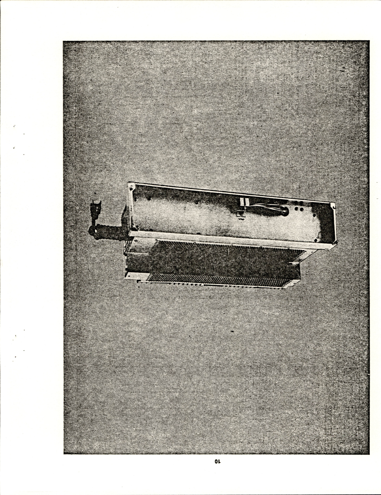
EG&G
ORTEC
402D
POWER
SUPPLY
1.
DESCRIPTION
The
EG&G
ORTEC
402D
Power
Supply
Is
designed
to
be
mounted
in
the
space
provided
on
the
rear
of
the
4001
A(B)
Modular
System
Bin.
The
Supply
was
designed
to
exceed
the
recommended
power
supply
specifica
tions,
Appendix
A
of
TID-20893
(Rev
3),
Type
V-H,
adopted
by
the
AEG
Committee
on
Nuclear
Instrument
Modules
(adopted
by
DOE).
The
402D
was
designed
for
worldwide
usage.
Input
volt
age
mains
of
117
V
ac
or
230
V
ac.
47-63
Hz,
may
be
used.
A
convenience
Indicating
switch
clearly
identifies
the
intended
main
to
use.
The
Supply
furnishes
six
standard
dc
voltages,
+24
V
at
1
A,
-24
V
at
1
A,
+12
V
at
2
A,
-12
V
at
2
A,
+6
V
at
8
A
and
—6
V
at
8
A,
with
a
maximum
power
capability
of
132
W
at
50°C.
The
dc
outputs
are
regulated,
short-circuit
pro
tected,
current
limited,
and
thermal
protected.
The
117
V
ac
is
supplied
to
the
Bin
connector
independ
ent
of
input
mains.
The
117-7
ac
power
available
Is
limited
only
by
the
Power
Supply
fuse
when
operating
from
117-V
ac
mains.
When
operating
from
230-V
ac
mains,
the
117-V
ac
Is
derived
by
autotransformer
action
and
is
limited
to
60
VA
output
with
a
dc
load
on
the
Power
Supply
of
132
W.
A
control
panel
is
provided
on
the
EG&G
ORTEC
4001
A(B)
Bin
for
operating
and
monitoring
the
402D
Power
Supply.
An
On-Off
switch,
a
power
indicating
lamp,
a
thermal
warning
lamp,
and
convenience
dc
moni
tor
jacks
are
provided.
The
thermal
warning
lamp
Is
lighted
when
the
internal
temperature
rises
to
within
20°
C
of
the
maximum
safe
operating
temperature.
The
Power
Supply
Is
automatically
cut
off
by
an
internal
switch
should
the
temperature
exceed
the
maximum
safe
operating
temperature.
The
power
transistors
are
virtually
indestructible
due
to
their
power
handling
capability,
current
limiting,
and
short-circuit
protection.
Silicon
semiconductors,
85°
C
capacitors
with
conservative
working
voltage
ratings,
high-quality-carbon
resistors,
and
metal
film
resistors
are
combined
to
produce
the
402D
Power
Supply,
which
exceeds
the
TID-20893
(Rev)
requirements.
The
dc
output
voltages
are
adjustable
through
holes
in
the
top
of
the
Power
Supply
cover
plate,
over
a
±2%
range
from
their
nominal
ratings.
The
adjustment
poten
tiometers
are
20-turn
cermet
potentiometers
for
superior
adjustment
resolution
and
resettability
of
the
output
volt
ages.
2.
SPECIFICATIONS
INPUT
100
to
129
V
ac,
57-63
Hz,
or
200
to
258
V
ac,
47-53
Hz.
Input
current
at
117
V
is
3.5
A
for
a
132-W
dc
output.
i
DC
OUTPUTS
The
Supply
provides
six
simultaneous
dc
outputs
with
the
following
current
ratings:
VOLTAGE
(V)
+24.00
-24.00
+12.00
-12.00
+
6.00
-
6.00
CURRENT
(A)
0
to
1
0
to
1
0
to
2
0
to
2
0
to
8
0
to
8
Maximum
output
power
from
0
to
50°
C
ambient
is
132
W.
Operation
to
60°
C
ambient,
with
current
derated
not
more
than
3%/°C
for
temperatures
above
50°
C.
117-V
AC
OUTPUT
117-V
ac
output
is
limited
only
by
the
Supply
fuses
when
operating
from
117-V
ac
mains.
Output
is
limited
to
60
VA
at
132-W
dc
load
while
operat
ing
from
230-V
ac
mains.
REGULATION
±0.1
%
(typically
±0.05%)
for
±12
V
and
±24
V,
and
±0.2%
(typically
±0.1%)
for
±6
V
over
the
combined
range
of
zero
to
full
load
and
input
voltage
of
100
to
129
V
ac
or
200
to
258
V
ac,
when
measurements
are
made
within
a
period
of
1
min.
±0.3%
(±12
V
and
±24
V)
and
±0.6%
(±6
V)
over
any
24-hr
period
at
constant
ambient
temperature
over
the
combined
range
of
no
load
to
full
load
and
input
voltage
of
100
to
129
V
ac
or
200
to
258
V
ac,
after
a
60-min
warmup.
STABILITY
Long-term
stability
over
a
6-month
period
is
better
than
±0.5%
after
a
1
-hr
warmup
at
constant
load,
line,
and
ambient
temperature.

12
OUTPUT
IMPEDANCE
<0.15n
for
the
±6-V
outputs
and
<0.3n
for
all
other
outputs
at
any
frequency
to
100
kHz.
TEMPERATURE
COEFFICIENT
range
of
0
to
60°
C.
<0.02%/°C
over
a
TEMPERATURE
PROTECTION
A
thermal
warning
switch
will
close
when
the
supply
temperature
ap
proaches
within
20°
C
of
the
safe
operating
value.
A
thermal
cutout
switch
disables
the
Power
Supply
when
the
temperature
exceeds
the
safe
operating
value.
NOISE
AND
RIPPLE
<3
mV
peak-to-peak
for
all
six
outputs,
as
observed
on
a
50-MHz
bandwidth
oscillo
scope.
VOLTAGE
ADJUSTMENTS
±2%
minimum
range,
reset-
tablllty
±0.05%
of
Supply
voltage.
CIRCUIT
PROTECTION
Both
sides
of
the
Input
line
to
the
power
supply
are
fused.
In
addition,
output
current
foldback
limiting
to
prevent
damage
to
the
Supply
and
automatic
recovery
when
the
demand
Is
removed
are
provided
by
electronic
circuitry.
All
six
supplies
are
protected
so
that
any
one
can
be
shorted
to
any
other
one
without
resulting
In
permanent
damage.
Overvoltage
protection
Is
provided
on
±6
V
so
that
these
outputs
will
not
exceed
7.5
V
maximum.
OUTPUT
CONNECTOR
All
power
and
control
circuits
terminate
In
a
connector,
specified
by
TID-20893
(Rev
3),
which
mates
the
Bin
Interface
connector,
completing
the
necessary
control
and
Power
Supply
wiring.
DIMENSIONS
Conform
to
AEG
drawing
ND-515
and
paragraph
L,
page
A-10,
of
TID-20893
(Rev
3).
RECOVERY
TIME
<100
fjs
to
return
to
within
±0.1%
of
rated
voltage
for
all
six
outputs
for
any
change
In
Input
voltage
and
load
current
from
10%
to
100%
full
load.
WEIGHT
Net
8.9
kg
(20
lb);
with
4001A(B)
13.6
kg
(30
lb).
Shipping
12.3
kg
(27
lb);
with
4001A(B)
19.6
kg
(43
lb).
3.
INSTALLATION
The
402D
Power
Supply
Is
normally
supplied
factory-
connected
to
an
EG&G
ORTEG
4001A(B)
Modular
Sys
tem
Bin.
However,
the
Supply
Is
designed
to
TID-20893
(Rev)
specifications
and
may
be
attached.
In
the
space
provided,
to
any
bin
manufactured
to
TID-20893
(Rev)
specifications.
For
attachment
to
other
than
an
EG&G
ORTEG
4001
A(B)
Bin,
refer
to
the
appropriate
Instruction
manual.
The
On-
Off
switch
and
other
controls
necessary
to
operate
the
supply
are
part
of
the
Bin
and
are
not
furnished
with
the
Power
Supply.
For
attachment
to
the
EG&G
ORTEG
4001A(B)
Bin
the
following
steps
are
advised:
1.
Place
the
Bin
on
a
table
with
the
back
part
facing
you.
Place
the
Power
Supply
In
the
proper
mounting
position,
leaving
enough
space
between
It
and
the
Bin
to
attach
the
Interface
connector.
2.
Mate
the
Interface
connector,
being
careful
to
align
the
polarizing
pins.
Fold
and
form
all
wiring
close
to
the
connector
edges
to
prevent
any
wires
from
being
pinched
and
producing
a
short
circuit
In
succeeding
steps.
3.
Mount
the
Supply
to
the
Bin
by
securely
tightening
the
four
10-32
screws,
being
careful
not
to
pinch
any
wires
or
to
use
undue
force
on
any
parts.
Unless
otherwise
specified,
the
402D
Is
shipped
with
transformer
connections
appropriate
for
operation
on
nominal
117
or
230
V
mains,
according
to
the
selection
made
with
the
rear
panel
slide
switch.
To
change
the
connections
for
operation
on
100
or
200
V
power
mains,
use
the
following
steps:
1.
Remove
the
top
cover.
2.
Move
the
wires
from
lug
#3
of
T1
to
Its
lug
#2.
3.
Move
the
wires
from
lug
#6
of
T1
to
Its
lug
#5.
4.
Replace
the
top
cover.
5.
Set
the
rear
panel
slide
switch
at
117
for
100
V
opera
tion
or
at
230
for
200
V
operation.

13
4.
OPERATING
INSTRUCTIONS
4.1
POWER
SUPPLY
LIMITATIONS
The
available
current
from
the
Power
Supply
is
given
in
Section
2.
Care
must
be
used
to
ensure
natural
convec
tion
of
heat
dissipated
by
the
heat
sinks
and
power
trans
former.
For
best
resuits,
when
using
at
maximum
power
loadings,
the
Bin
and
Power
Supply
should
be
in
an
open
space,
piaced
upon
blocks
at
least
1
in.
off
the
table
mounting
surface
to
allow
maximum
ventilation.
When
used
in
a
rack,
maximum
attention
should
be
paid
to
placement
of
other
heat-generating
equipment.
Ade
quate
unobstructed
space
on
all
sides
is
necessary
for
convection
ventilation
and
cooling.
If
the
Bin
contains
other
heat-generating
equipment,
a
blower
may
be
advisable
to
remove
the
dissipated
heat.
When
it
is
necessary
to
rack-mount
severai
bins
and
power
supplies,
especially
when
other
heat-generating
equipment
is
located
within
the
rack,
the
term
"ambient
temperature"
becomes
less
clearly
defined.
A
better
guide
to
maximum
power
loading
capability
is
to
monitor
the
heat
sink
temperature.
Never
allow
the
heat
sink
temperature
to
continuously
run
above
lOCC.
Although
this
is
not
the
maximum
operation
temperature,
any
addi
tional
temperature
rise
due
to
other
conditions
of
the
sys
tem
may
force
the
Supply
out
of
tolerance
and
may
cause
it
to
automaticaily
shut
down
operation.
Should
your
operation
produce
a
temperature
of
100°C,
a
blower
to
remove
the
dissipated
heat
is
recommended.
4.2
6-V
POWER
SUPPLIES
CROWBAR
OPERATION
Both
the
-f-e-V
and
the
-S-V
outputs
are
protected
against
overvoltage.
If
for
any
reason
one
of
these
output
voltages
exceeds
7.5
V
maximum
in
absolute
value
an
internal
"crowbar
circuit"
is
triggered,
which
places
a
short-circuit
across
the
output
of
the
corresponding
volt
age.
Since
this
circuit
contains
an
SCR,
normal
opera
tion,
after
suppression
of
the
cause
of
the
overvoitage,
can
be
resumed
only
by
turning
the
power
switch
of
the
4001
Bin
to
Off
for
a
couple
of
seconds,
and
then
turning
it
to
On
again.
If
in
normal
operation
it
is
suddenly
discovered
that
the
+6-\/
or
-6-V
output
is
missing,
first
check
whether
it
can
be
restored
by
following
this
procedure,
after
having
removed
all
the
modules
from
the
Bin.
The
crowbar
pro
tection
circuit
of
the
corresponding
voitage
may
have
been
triggered
by
a
temporary
fault
in
one
module
or
even
by
a
strong
spurious
voltage
transient.
5.
CIRCUIT
DESCRIPTION
5.1.
GENERAL
DESCRIPTION
The
402D
Power
Supply
produces
six
dc
output
voltages;
±12
V,
±24
V,
and
±6
V.
A
power
transformer
reduces
the
input
ac
line
volfage
into
six
separate
low
voltage
sources.
Each
voltage
source
has
a
separate
full-wave
bridge,
a
filter
capacitor,
and
an
electronic series
regula
tor.
Each
regulator
is
composed
of
discrete
solid-state
devices
and
is
completely
independent
from
all
other
output
regulators.
The
six
regulators
are
packaged
on
three
plug-in
printed
circuit
boards.
The
board
closest
to
the
heat
sink
includes
regulators
for
the
±6
V
supplies.
The
board
in
the
middle
includes
regulators
for
the
negative
12
and
24
V
supplies.
The
other
board
includes
regulators
for
the
positive
12
and
24
V
supplies.
The
12
V
and
24
V
regulator
boards
are
identical
and
may
be
interchanged.
The
rectifiers,
series
pass
transistors,
sense
resistors,
and
the
SCRs
for
the
6
V
supplies
are
all
located
on
the
large
heat
sink.
The
filter
capacitors
for
the
12
V
and
24
V
supplies
are
located
on
their
regulator
boards.
The
filter
capacitors
for
the
6
V
supplies
are
mounted
in
the
power
suppiy
chassis.
5.2.
OPERATION
OF
REGULATORS
The
operation
of
the
±12
V
and
±24
V
regulators
are
all
identical.
The
+24
V
regulator
is
discussed
here
as
an
example
that
is
typical
for
all
four
of
these
supplies.
The
circuit
is
shown
on
schematic
402D-0201-S1.
The
circuit
consists
of
two
parts;
these
are
the
voltage
regulator
and
the
current
foldback
circuit.
The
voltage
regulator
includes
Q10,
Q11,
Q3,Q4,
Q2,Q1,
and
Q101.
The
current
foldback
circuit
includes
Q5,Q7,
Q8,06,
and
09.
Transistors
010
and
Oil
operate
as
a
differential
ampli
fier,
comparing
the
voltage
from
the
reference
diode,
D4,
at
the
base
of
010
to
the
output
voltage
divided
down
by
resistors
R21,R22,
and
R23.
Potentiometer
R22
is
used
to
adjust
the
output
voltage
to
the
desired
level.
The
differ
ence
voltage
is
amplified
by
03
and
04
to
reduce
the
current
through
02
and
to
increase
the
output
voltage
or
14
to
increase
the
current
through
Q2
and
to
then
decrease
the
output
voltage.
Q2
drives
emitter
follower
Q1
to
supply
drive
current
for
series
pass
element
Q101.
In
the
current
limiting
mode,
the
voltage
across
sense
resistor
R101
is
applied
between
the
bases
of
Q6
and
Q9.
When
the
current
level
is
less
than
the
rated
current,
Q6
and
Q7
conduct.
If
the
output
current
exceeds
its
rated
value,
the
voltage
at
the
base
of
Q6
goes
higher
than
the
voltage
at
the
base
of
Q9
and
Q9
conducts.
This
turns
Q8
on
to
increase
the
current
through
Q2
and
to
decrease
the
current
drive
to
the
base
of
Q1.
The
amount
of
current
that
the
series
pass
element,
Q101,
can
supply
is
reduced.
When
the
over-current
condition
is
corrected,
normal
regulation
returns
automatically.
The
±6
V
regulators
operate
much
the
same
as
the
+24
V
regulator.
The
circuit
for
the
±6
V
regulators
is
shown
on
schematic
402D-0301
-SI.
The
sense
amplifier
of
the
+6
V
regulator
includes
Q11, Q10,
Q9,
Q26,
Q4,
Q5,
Q2.
Q1,
and
Q3.
The
operation
is
the
same
as
for
the
+24
V
regu
lator.
The
addition
of
Q9
and
Q26
provides
a
constant
current
for
reference
diode
D11.
In
the
current
limiting
mode,
operation
is
the
same
as
for
the
+24
V
regulator.
Resistors
R105
through
R108
are
used
to
balance
the
current
in
the
four
series
pass
tran
sistors,
Q105
through
Q108.
R108
is
also
used
as
a
sense
resistor.
The
four
transistors
are
used
to
keep
the
power
dissipated
in
each
device
below
the
maximum
rated
value.
The
"crowbar"
circuit
is
used
for
over-voltage
protection.
It
includes
Q12,
D12,
and
SCR
D107.
If
the
output
voltage
exceeds
the
zener
voltage
of
D12
(~6.8
V),
Q12
turns
on
and
triggers
the
gate
of
the
SCR.
When
the
SCR
turns
on,
it
appears
as
a
short
across
the
supply
output
and
causes
the
current
to
fold
back.
After
the
cause
of
the
over-
voltage
has
been
removed,
the
supply
must
be
switched
off
for
two
seconds
and
can
then
be
turned
on
again
to
restore
its
normal
operation.
6.
MAINTENANCE
6.1.
ACCESS
The
top
cover
of
the
402D
Power
Supply
is
attached
with
sixteen
4-40
Phillips-head
machine
screws.
When
all
16
screws
are
removed
the
cover
can
be
lifted
for
access
to
the
plug-in
regulator
boards.
Each
regulator
board
has
keying
pins
to
prevent
reversal
of
position
in
the
connec
tor
and
to
prevent
insertion
into
the
incorrect
location.
Be
very
careful
to
prevent
breaking
or
removing
the
keying
pins
from
the
connector
during
either
removal
or
return
of
the
board.
There
are
copper
clips
attached
to
some
of
the
transis
tors
on
the
printed
circuit
boards.
Their
purpose
is
to
ensure
equal
operating
temperatures
for
these
transis
tors.
Do
not
remove
the
copper
clips
from
these
transis
tors.
Most
of
the
components
mounted
on
the
heat
sink
can
be
replaced
easily.
If
access
is
required
to
the
chassis
side
of
the
heat
sink,
remove
the
14
mounting
screws
that
secure
it
to
the
chassis
and
carefully
fold
the
heat
sink
away
from
the
chassis
to
prevent
breaking
any
of
the
wire
leads
or
the
soldered
connections.
6.2.
TROUBLESHOOTING
Any
of
the
three
transistor
boards
may
be
operated
separately
without
requiring
the
other
boards
to
be
installed
in
the
power
supply.
If
an
output
voltage
is
high
and
cannot
be
adjusted
down
to
its
proper
level,
its
series
pass
transistor,
mounted
on
the
heat
sink,
may
be
shorted.
This
condition
will
usually
cause
damage
to
the
regulator
that
is
mounted
on
the
printed
circuit
board.
Check
the
emitter-base
junction
of
the
series
pass
transistor
with
an
ohmmeter
if
a
short
is
suspected.
Do
not
install
another
regulator
board
if
the
transistor
is
shorted,
or the
new
board
will
be
damaged.
Since
the
positive
12/24
V
regulator
board
is
identical
to
the
negative
12/24
V
regulator
board,
the
boards
can
be
interchanged
for
troubleshooting.
Replacement
regula
tor
boards
are
available
from
EG&G
ORTEC.
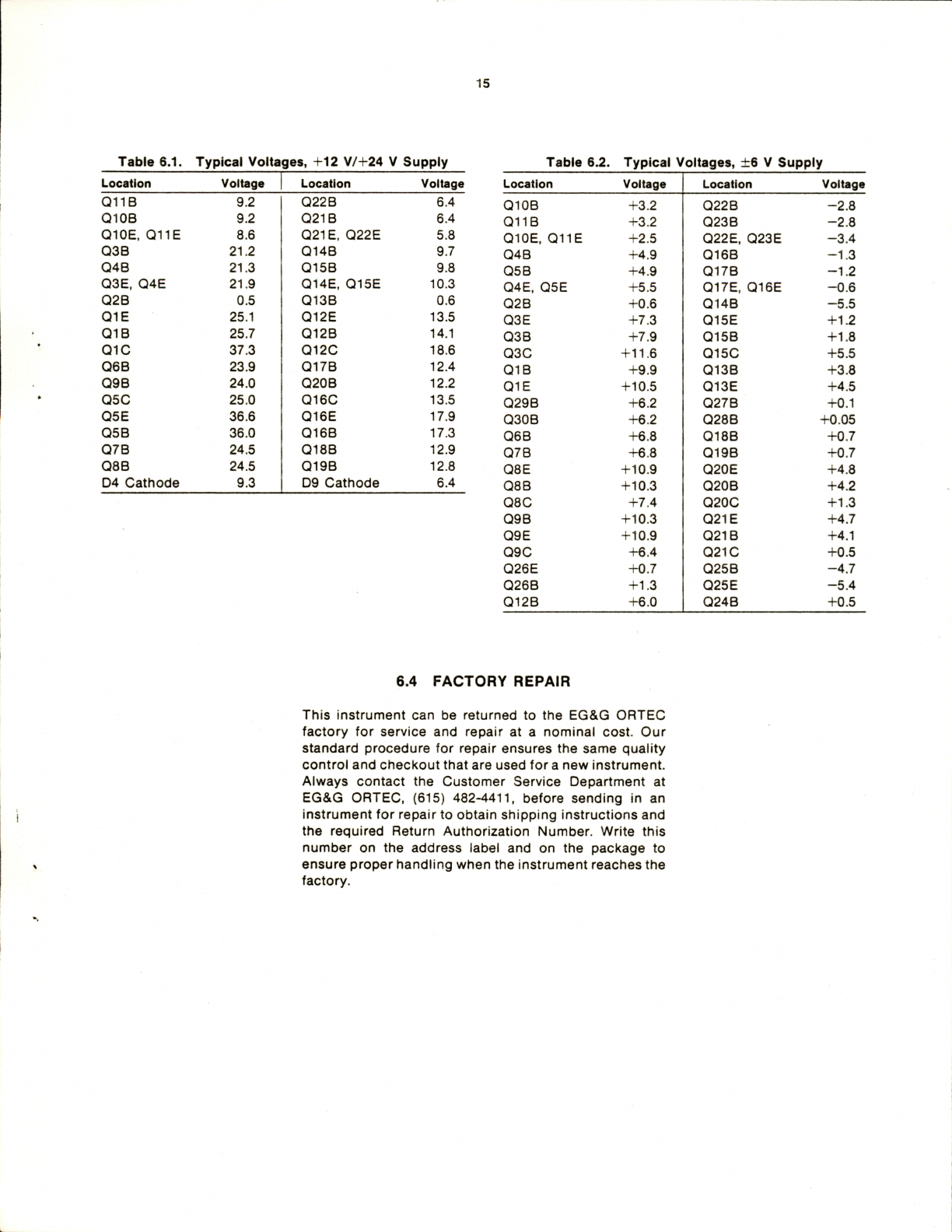
6.3.
TYPICAL
VOLTAGES
Tables
6.1
and
6.2
list
typical
voltages
that
were
meas
ured
with
respect
to
ground
potential
and
they
are
given
here
as
an
aid
in
troubleshooting.
These
voltage
levels
are
typical
of
a
circuit
that
is
operating
properly,
but
the
precise
values
will
vary
between
individual
circuits.
The
12/24
V
table
indicates
the
voltages
on
the
board
when
it
is
installed
at
the
positive
location,
furthest
from
the
heat
sink.
Line
voltage
is
117
V
ac.
The
24
V
supply
is
loaded
for
1
A
and
the
12
V
supply
is
loaded
for
2
A.
All
measurements
are
referenced
to
chassis
ground
and
are
made
with
a
voltmeter
that
has
a
10
MO
input
impedance.
The
regulator
board
for
the
±6
V
supplies
operates
in
the
location
closest
to
the
heat
sink.
The
following
voltages
assume
a
line
voltage
of
117
V.
Each
supply,
+6
V
and
—6
V,
is
loaded
for
8
A.
All
measurements
are
referenced
to
chassis
ground
and
are
made
with
a
voltmeter
that
has
a
10
Mn
input
impedance.
15
Table
6.1.
Typical
Voltages,
+12
V/+24
V
Supply
Table
6.2.
Typical
Voltages,
±6
V
Supply
Location
Voltage
Location
Voltage
Location
Voltage
Location
Voltage
Q11B
9.2
022
B
6.4
Q10B
+3.2
Q22B
-2.8
Q10B
9.2
021
B
6.4
Q11B
+3.2
Q23B
-2.8
Q10E,
Q11E
8.6
021E,
Q22E
5.8
Q10E,
Q11E
+2.5
Q22E,
Q23E
-3.4
Q3B
21.2
Q14B
9.7
Q4B
+4.9
Q16B
-1.3
Q4B
21.3
Q15B
9.8
05
B
+4.9
Q17B
-1.2
Q3E,
Q4E
21.9
Q14E,
Q15E
10.3
Q4E,
05E
+5.5
Q17E,
Q16E
-0.6
Q2B
0.5
Q13B
0.6
Q2B
+0.6
Q14B
-5.5
Q1E
25.1
Q12E
13.5
Q3E
+7.3
Q15E
+1.2
01B
25.7
Q12B
14.1
Q3B
+7.9
Q15B
+1.8
QIC
37.3
Q12C
18.6
030
+11.6
0150
+5.5
Q6B
23.9
Q17B
12.4
01B
+9.9
Q13B
+3.8
Q9B
24.0
Q20B
12.2
01E
+10.5
Q13E
+4.5
050
25.0
0160
13.5
Q29B
+6.2
027
B
+0.1
Q5E
36.6
Q16E
17.9
Q30B
+6.2
028
B
+0.05
Q5B
36.0
Q16B
17.3
06
B
+6.8
Q18B
+0.7
Q7B
24.5
Q18B
12.9
07
B
+6.8
Q19B
+0.7
Q8B
24.5
Q19B
12.8
08
E
+10.9
Q20E
+4.8
04
Cathode
9.3
09
Cathode
6.4
Q8B
+10.3
Q20B
+4.2
080
+7.4
Q20C
+1.3
09
B
+10.3
021E
+4.7
09E
+10.9
021B
+4.1
090
+6.4
021G
+0.5
Q26E
+0.7
Q25B
-4.7
Q26B
+1.3
025
E
-5.4
Q12B
+6.0
Q24B
+0.5
6.4
FACTORY
REPAIR
This
instrument
can
be
returned
to
the
EG&G
ORTEC
factory
for
service
and
repair
at
a
nominal
cost.
Our
standard
procedure
for
repair
ensures
the
same
quality
control
and
checkout
that
are
used
for
a
new
instrument.
Always
contact
the
Customer
Service
Department
at
EG&G
ORTEC,
(615)
482-4411,
before
sending
in
an
instrument
for
repair
to
obtain
shipping
instructions
and
the
required
Return
Authorization
Number.
Write
this
number
on
the
address
label
and
on
the
package
to
ensure
proper
handling
when
the
instrument
reaches
the
factory.
i
0
-(BZS-
I
-{SO-
(S)
-SID—
^
|a
-{HB-
(D
I
-iSS
n
—fRSaT—
@
'
—fgzl
N
-cm^K^rizten}-
--0
40.;
U-O20I©
IR
C
CO
UMttM
01WWW
$1
ORTEC
Afi
t*3«0cicav»*js|>'
irvJC30F4H=>CDMArei3
lOO
MIDLAND
ROAD.
OAK
RIDOE,
TENNESSEE
37830
MLV
B-Zt-74
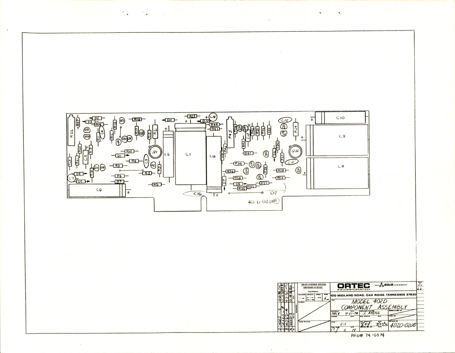
MODEL
402D
rnMPDNEA/T
ASSEMBLY
J.
AYS/rs
402D-0100
RFC#
74
-05
74
This manual suits for next models
1
Table of contents
Other EG&G Power Supply manuals

Popular Power Supply manuals by other brands

Puls
Puls PIC480.241C installation manual

Zennio
Zennio ALLinBOX 1612 v2 manual

Delta Elektronika
Delta Elektronika SM 15-400 product manual

Test Equipment Depot
Test Equipment Depot PS-1303C user manual

Agilent Technologies
Agilent Technologies 6622A Service manual

Philips
Philips dynalite DDNP1501 installation instructions


