manuals.online logo
Brands
  1. Home
  2. •
  3. Brands
  4. •
  5. EGi
  6. •
  7. Adapter
  8. •
  9. EGi AV Device DIN Adapter User manual

EGi AV Device DIN Adapter User manual

AV Device DIN Adapter
User Instructions
8400392-51 (20150805)
When using an experimental control system with the EGI Geodesic
EEG System (GES) and the Net Amps (300 or 200), the AV Device DIN
Adapter can function one of two ways. It can let you operate your
experimental control system through a PC or it can let you investigate
the precision and accuracy of the stimulus markers that are conveyed
via the Net Amps DIN port and recorded along with the EEG. The AV Device DIN Adapter, depending upon its setting, sends
signals from the AV Device Tester and/or a computer’s parallel port to the Net Amps DIN port.
Included in the AV Device Accessories Kit:
!AV Device DIN Adapter
!15 ft M-M DB-25 straight-
through cable
!15 ft M-M DB-9 straight-
through cable
!Instructions
I. Connections
1Set the switch of the AV Device DIN Adapter as follows:
•When using the AV Device Tester to test a CRT monitor with a photocell, turn the switch to AVD DIN1.
•When using the AV Device Tester to test audio, turn the switch to AVD DIN2.
•When using the AV Device Tester to test an LCD monitor with a photocell, turn the switch to AVD DIN3.
•When using the AV Device DIN Adapter to connect a PC to the Net Amps for the operation of your experimental
control system, turn the switch to PC DIN1.
For normal operation, be aware that you also need to change the selection in the Source tab panel of the
Digital Inputs Control panel. Select EGI Response Pad. Refer to the Net Station Acquisition Technical Manual.
Note: When AVD DIN1, AVD DIN2, or AVD DIN3 is selected, the output appears in Net Station on DIN1 of the Digital Inputs Control panel.
2Remove power from all components, until after they are connected.
3Using the provided cables, connect the AV Device DIN Adapter to the AV Device Tester, Net Amps (200 or 300), and
computer (if used) as shown in Figure 1. Adhere to all requirements in other device manuals for those devices.
4For advanced uses of the AV Device DIN Adapter, refer to the pin outs that are listed in the Pin Outs section.
II. Pin Outs
Following are the pins that pass signals through the ports of the AV Device DIN Adapter based on the switch position.
Table 1. Pin outs based on the position of the AV Device DIN Adapter switch
Switch Position
Port
Pins That Pass Signals Through Ports
AVD DIN 1
AVD DIN1
AVD DIN2
AVD DIN3
PC DIN1
AV Device Input
1
NC
GND
NC
NC
NC
NC
PC Parallel Port Input
3
4
5
25
6
7
8
9
Amp DINS Output
1
2
3
4
GND
6
7
8
9
AVD DIN 2
AVD DIN1
AVD DIN2
AVD DIN3
PC DIN1
AV Device Input
2
NC
GND
NC
NC
NC
NC
PC Parallel Port Input
3
4
5
25
6
7
8
9
Amp DINS Output
1
2
3
4
GND
6
7
8
9
AVD DIN 3
AVD DIN1
AVD DIN2
AVD DIN3
PC DIN1
AV Device Input
3
NC
GND
NC
NC
NC
NC
PC Parallel Port Input
3
4
5
25
6
7
8
9
Amp DINS Output
1
2
3
4
GND
6
7
8
9
PC DIN 1
AVD DIN1
AVD DIN2
AVD DIN3
PC DIN1
AV Device Input
NC
GND
NC
NC
NC
NC
PC Parallel Port Input
2
3
4
5
25
6
7
8
9
Amp DINS Output
1
2
3
4
GND
6
7
8
9
User Instructions for the AV Device DIN Adapter
8400392-51
PC PARALLELPORT INPUT
AVDDIN1
AVDDIN2
AVDDIN3
PC DIN1
AV Device DIN Adaptor
AVDEVICE INPUT
AMP DINS OUTPUT
AV Device DIN Adapter
AV Device Tester Net Amps 200
Isolated
Outputs
2 V
400 µV
Photocell Audio Chart
Power DIN1
DINs
Output
DIN2 DIN3
9 VDC
+-
Inputs
AV Tester
Electrical Geodesics, Inc.
+1.541.687.7962 USA
DB-9 M-M cable
(provided with the AV Device Tester)
DB-9 M-M cable
(provided with the AV Device DIN Adapter)
connects to the NA300 --- or --- the NA200
DB-25 M-M cable
(provided with the AV Device DIN Adapter)
Hypergrip
cable
(EGI 6503376)
ARRAY DATA TIMING
Net Amps 300
Digital Analog
E-Prime PC
AdapterTester
Testing____ Setting Setting _
CRT monitor AVD DIN1 Photocell
Audio AVD DIN2 Audio
LCD monitor AVD DIN3 Photocell
____________________________________
*Refer to the AV Device Tester manual for
complete usage and safety instructions.
Attach to AV Device Tester* if testing:
AdapterTester
Use________ Setting Setting __ __
Experimental PC DIN1 N/A
control system
_______________________________________
*You also need to change the Source tab panel
selection to EGI Response Pad, because the
adapter inverts the parallel port signal.
Attach to PC for normal operation*:
*Refer to the Net Amps
manual for complete
usage and safety
instructions.
Attach to your
Net Amps*
(300 or 200).
Figure 1. Cable connections and settings when using the AV Device DIN Adapter for testing or normal operation
For questions or additional assistance, please contact us at:
Electrical Geodesics, Inc. (EGI)
500 E 4th Avenue, Suite 200
Eugene, OR 97401 USA
+1.541.687.7962 !s[email protected] !www.egi.com

Popular Adapter manuals by other brands

NewerTech VIDU3DVIA quick start guide

NewerTech

NewerTech VIDU3DVIA quick start guide

RF RX0696-3008-31B quick start guide

RF

RF RX0696-3008-31B quick start guide

TRENDnet TEW-649UB - Mini Wireless N Speed USB 2.0... Quick installation guide

TRENDnet

TRENDnet TEW-649UB - Mini Wireless N Speed USB 2.0... Quick installation guide

D-Link DWA-162 Quick install guide

D-Link

D-Link DWA-162 Quick install guide

INFOSEC U90 EXTRA SLIM user guide

INFOSEC

INFOSEC U90 EXTRA SLIM user guide

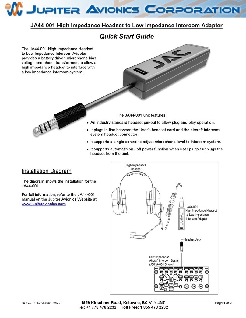
Jupiter Avionics JA44-001 quick start guide

Jupiter Avionics

Jupiter Avionics JA44-001 quick start guide

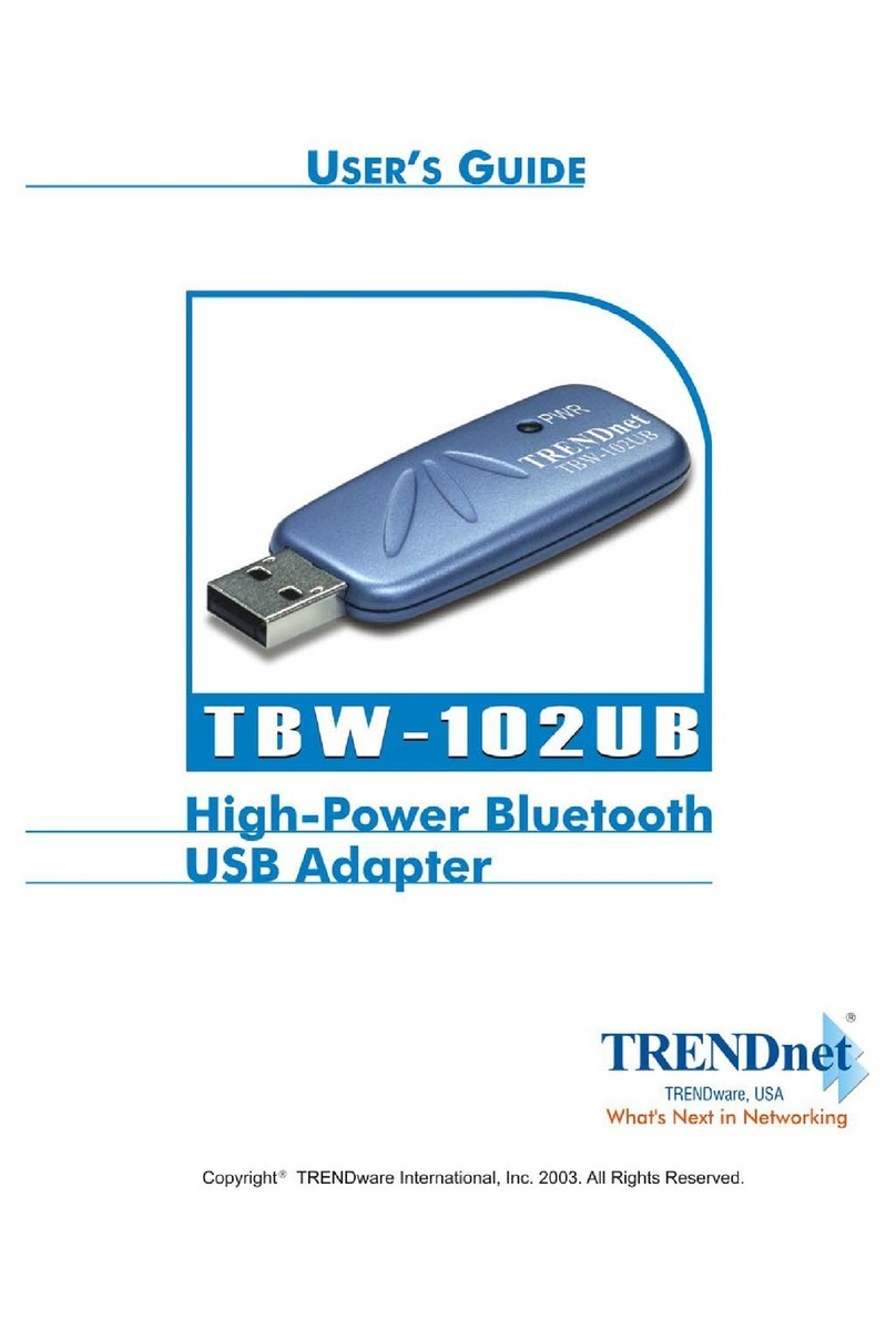
TRENDnet TBW-102UB user guide

TRENDnet

TRENDnet TBW-102UB user guide

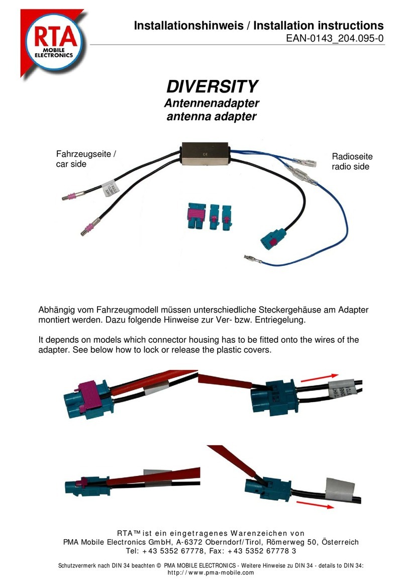
PMA RTA DIVERSITY installation instructions

PMA

PMA RTA DIVERSITY installation instructions

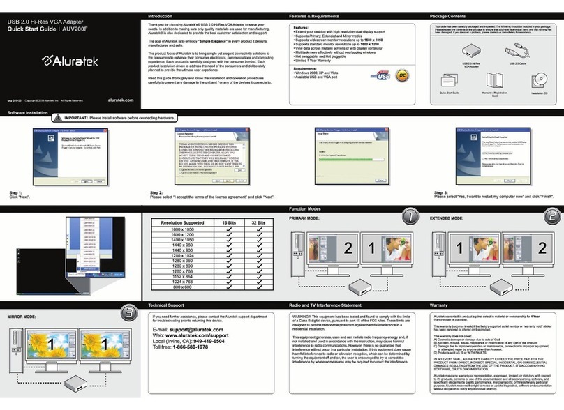
Aluratek AUV200F quick start guide

Aluratek

Aluratek AUV200F quick start guide

FLENDER N-EUPEX operating instructions

FLENDER

FLENDER N-EUPEX operating instructions

Hanlong Unicorn 3101 user manual

Hanlong

Hanlong Unicorn 3101 user manual

Scientific Atlanta WebSTAR DPW941 user guide

Scientific Atlanta

Scientific Atlanta WebSTAR DPW941 user guide

Accell UltraAV DisplayPort Setup instructions

Accell

Accell UltraAV DisplayPort Setup instructions

Panasonic BL-PA100KT Brochure & specs

Panasonic

Panasonic BL-PA100KT Brochure & specs

Rosewill RNX-G1 user manual

Rosewill

Rosewill RNX-G1 user manual

Adaptec Adaptec RAID Controller user guide

Adaptec

Adaptec Adaptec RAID Controller user guide

Vanguard Instruments CT-7500 S2 user guide

Vanguard Instruments

Vanguard Instruments CT-7500 S2 user guide

TRENDnet TU2-ET100 user guide

TRENDnet

TRENDnet TU2-ET100 user guide

manuals.online logo
manuals.online logoBrands
  • About & Mission
  • Contact us
  • Privacy Policy
  • Terms and Conditions

Copyright 2025 Manuals.Online. All Rights Reserved.