Ehong EH-MC10-MESH-EVK User manual

Eho Ehong Technology Co.,Ltd
!
EH-MC10-MESH-EVK USER GUIDE
Features
•Bluetooth® Radio
-Fully embedded Bluetooth® v4.0 single
mode
-TX power +7dbm,-92.5dbm RX sensitivity
-128-bit encryption security
-Range up to 70m
-Integrated chip antenna
•Support Profiles
-Mesh network node
-Sensor
-Switch
•User Interface
- Firmware upgrade over the air (OTA)
- USB or two dry batteries supply
- Debug SPI interface
- RGB LED display
-Buzzer
•USB or two dry batteries supply
•Operating temperature range:
-30 °C to 80 °C
General Description
The EH-MC10-Mesh-EVK is mesh development
kit for CSRmesh.
The development board internal integration
RGB LED display, buttons, buzzer, battery hold-
er, digital Temperature Sensor , AIO interface
and debug SPI interface.
Application
Smart Home, Smart Industrial, Smart City
V1.1
Dec 18 2016

VERSION HISTORY
Confidential and Proprietary – Ehong Technology Co.,Ltd
NO PUBLIC DISCLOSURE PERMITTED: Please report postings of this document on public
Restricted Distribution: Not to be distributed to anyone who is not an employee of either
Ehong Technology Co.,Ltd or its affiliated companies without the express approval of Ehong
Configuration Management.
Not to be used, copied, reproduced, or modified in whole or in part, nor its contents revealed in
any manner to others without the express written permission of Ehong Technology Co.,Ltd.
This Bluetooth trademark is owned by the Bluetooth SIG Inc., USA and is licensed to Ehong
Technologies. All other trademarks listed herein are owned by their respective owners.
© 2016 Ehong Technology Co.,Ltd. All rights reserved.
Version
Comment
V1.0
V1.1
Update the Package
Full Production Release

Content
1、Introduction 1
2、Package 1
3、Connecting up the Hardware 2
4、Using the Smartphone APP 3
4.1 Light Control Application Overview 3
4.2 Main Menu 4
4.3 Places 4
4.4 Managing Places 5
4.5 Creating a New Place 6
4.6 Areas 7
4.6.1 Creating New Areas 7
4.6.2 Configuring an Area 8
4.6.3 Controlling an Area 9
5、CSRmesh Devices 10
5.1 Adding New Devices 11
5.1.1 Detected Device List 11
5.1.2 Scanning QR Code 13
5.1.3 Setting Short Code 13
5.2 Configuring Existing Devices 13
5.2.1 Deleting a Device 14
5.2.2 Renaming a Device 14
5.2.3 Assigning Areas to a Device 14
5.2.4 Assign a Device as a Favourite 15
5.3 Controlling a Device 15
5.3.1 Lights 15
5.3.2 Thermostat and Heater Control 16
6、Settings 17
6.1 Gateway Configuration 18
6.2 Edit Gateway 18
6.3 Deleting a gateway 19
7、Consumption 20
8、Contact Information 20

1、Introduction
This is documentation helps you set up and use the CSRmesh
Development Kit for EH-MC10.
2、Package
For the mesh network testing, the following components are suggest-
ed:
3 ×EH-MC10 demo board(For LED, for Sensor, for switch is se-
lected)
1 ×SPI Programmer and SPI interface Cable
6 ×AA alkaline batteries(2 for each Target Board)
Page of 201

3、Connecting up the Hardware
it is now safe to power on the target board and connect it to the APP
of phone.
1. Remove the target board from the packaging at an approved
workstation
2. Install 2x AA batteries into battery holders on the reverse of the
board, observing the correct polarity, or use USB connect to PC for
power supply
3. Set the Power On/Off with on the Target board to the VBAT position
Page of 202
Positive
Positive
Figure 3.1: Target Board (reverse)
Power Switch(ON)
SPI Connector
USB power supply
Figure 3.2: Target Board (front)

4. Connect the Target board to the SPI programmer using the SPI cab
5. Connect the smaller connector of the cable to the SPI programmer
6. Connect the other end of the USB cable to free USB port on the
development PC
7. The device drivers reference SPI user guide
4、Using the Smartphone APP
This section describes how an android smartphone app can connect
to the Light control application running on the target board and
control the LED located in it.
An iOS version of the app also available.
4.1 Light Control Application Overview
The CSRmesh light control application allows the user to control devices
within the CSRmesh Network.
The Android application works by connecting to CSRmesh device. This
device acts as a bridge from the Android application to the rest of the
Page of 203
SPI Connector
USB Connector
Figure 3.3: SPI Programmer

CSRmesh network. The following section describes how to use the
CSRmesh Android application to control light devices that are part of a
CSRmesh network.
4.2 Main Menu
The main menu is available via the hamburger menu icon on the top
right of the application. This displays the menu options shown in
Figure 4.1. From this menu you can manage places, login to the cloud
via Facebook and control manage and set up the CSRmesh network.
4.3 Places
The current selected place is displayed on the main menu as shown in
Figure 2.1. Selecting the down arrow from the main menu displays the
configured and shared places and options to manage and create new
places as shown in Figure 4.2
Page of 204
Figure 4.1: Main Menu

4.4 Managing Places
Selecting Manage places allows you to manage existing places and
create new places to control as shown in Figure 4.3. Selecting the plus
icon allows you to create a new place to control, while selecting the
settings icon next to existing places allows you to configure an existing
place.
Page of 205
Figure 4.2: Places
Figure 4.3: Managing Places

4.5 Creating a New Place
To create a new place, select the plus icon from within Manage places
or select Create a new place from the places menu. A new place can
be defined as shown in Figure 4.4. This allows you to define the place
name, icon and color. Additionally you need to define the Network key
passphrase for this new place.
When creating a new place, you can also select to import a database
file from a previously created place using the IMPORT DATABASE
option. See Section Error! Reference source not found. for details on
sharing places.
Page of 206
Figure 4.4: Creating a New Place

4.6 Areas
Selecting the Areas option allows you to control and configure existing
areas and create new areas within the currently selected place as
shown in Figure 4.5.
4.6.1 Creating New Areas
Selecting the plus icon allows you to create a new area within to the
currently selected place. The new area can be configured as shown in
Figure 6.2.
Note:
Devices cannot be assigned until the areas has been created and
saved.
Page of 207
Figure 4.5: Areas

4.6.2 Configuring an Area
Selecting the settings icon next to an area allows you to configure and
edit the selected area as shown in Figure 4.6:
1. Deleting an Area
Selecting the delete icon will prompt you to accept or cancel the
delete operation. Selecting Accept will remove the area from the
current selected place and remove any device assignments.
2. Renaming an Area
You can rename the area by editing the associated AREA NAME field.
No changes will be applied until you select the tick icon to accept the
changes. Selecting the OS back option will discard all changes.
3. Assigning Devices to an Area
You can select the device edit icon to assign devices to an area as
shown in Figure 4.7: . You can select multiple devices from the list of
available devices to assign to the area. When a device is selected, the
tick icon is shown. No area configuration changes will be applied until
Page of 208
Figure 4.6: Areas

you select the tick icon to apply the changes. Selecting the OS back
option will discard all changes. It is also possible to assign devices to
areas when configuration device as described in Section 0.
4. Assigning an Area as a Favourite
Selecting the star icon on the area will add or remove the device to the
favourite list.
Note:
Not currently supported
4.6.3 Controlling an Area
Selecting the area allows you to control the area settings as shown in
Figure 4.8. This allows you to control the devices within the area
together, e.g. lights or heating.
Page of 209
Figure 4.7: Area Device Assignment

5、CSRmesh Devices
Selecting CSRmesh devices allows you to control and configure
existing devices and add new devices to the currently selected place.
Figure 5.1: shows a places configuration of two lights, a thermostat
and a heater. Selecting the search icon allows you to filter the
CSRmesh device list to find devices to configure and control.
Page of 2010
Figure 4.8: Controlling an Area
Figure 5.1: CSRmesh Devices

5.1 Adding New Devices
Selecting the plus icon allows you to add a new device to the currently
selected place. There are three methods of adding a new device as shown
in Figure 5.2. After a device has been added, the device will appear within
the CSRmesh device list to where it can be configure as described in
section 5.2.
5.1.1 Detected Device List
Selecting this option will scan for un-associated CSRmesh devices that
are advertising the CSRmesh UUID. Available devices will be listed
when they are discovered as shown in Figure 5.3.
Page of 2011
Figure 5.2. Adding a New Device
Figure 5.3. Detected Devices

You can select a device to associate which will highlight the selected
device as shown in Figure 5.4. If supported on the CSRmesh device, it
should indicate that the device has been selected to be associated.
(e.g. flashes an LED)
If the device selected is not the correct device to add, you can select
another device. If the device is the correct device to be added, you
can then select ASSOCIATE DEVICE as shown in Figure 5.5.
Note:
The association can be cancelled by tapping on the cancel button
once the association has been initiated.
Page of 2012
Figure 5.4. Detected Device Selected

5.1.2 Scanning QR Code
Selecting this option prompts you to scan a QR code that contains the
UUID and Access Code of the device to be associated. After
successfully scanning a valid QR code, the device association will start
as shown in Figure 5.5.
Note:
This requires a QR scanner application to be installed on the Android
device.
5.1.3 Setting Short Code
Selecting this option allows you to manually enter the short code of
the device to be associated. After entering the short code the device
association will start as shown in Figure 5.5.
5.2 Configuring Existing Devices
Selecting the settings icon next to each device allows you to configure
and edit the selected device as shown in Figure 7.6 for a light and a
Page of 2013
Figure 5.5. Association

thermostat CSRmesh device. Also, when a device is associated the
configuration screen will come up to allow you to edit the device.
5.2.1 Deleting a Device
Selecting the delete icon will prompt you to accept or cancel the
delete operation. Selecting Accept will remove the CSRmesh device
from the current selected place and assigned areas.
5.2.2 Renaming a Device
You can rename the CSRmesh device by editing the associated DEVICE
NAME field. Any changes will not be applied until you select the tick icon to
accept the changes. Selecting the OS back option will discard all changes.
5.2.3 Assigning Areas to a Device
You can select the area edit icon to assign a device to an existing or
new area as shown in Figure 5.7. You can select multiple areas from
the list of available areas to assign to the device. When an area is
selected, the tick icon shows. Additionally you can create a new area
by selecting the NEW GROUP option. After the new area is created,
Page of 2014
Figure 5.6. Configuring Devices

the device can be assigned to the area accordingly. Any area
configuration changes will not be applied until you select the tick icon
to apply the changes. Selecting the OS back option will discard all
changes. It is also possible to assign devices to areas when
configuring areas as described in Section 0.
5.2.4 Assign a Device as a Favourite
Selecting the star icon on the device will add or remove the device to
the favourite list.
Note:
Not currently supported.
5.3 Controlling a Device
Selecting a device allows you to control the device settings. The type
of controls shown depends on the type of device selected.
5.3.1 Lights
Figure 5.8 shows the light control. This allows you to set the desired
color and brightness. Additionally the light can be turned on or off.
Page of 2015
Figure 5.7. Assigning a Device to an Area

Note:
The state of this control reflects the last known state. It may not
represent the actual state if the device state is modified from another
controller.
5.3.2 Thermostat and Heater Control
Figure 5.9 shows the temperature control. This allows you to set the desired
temperature and read the current temperature.
Page of 2016
Figure 5.8. Assigning a Device to an Area
Figure 5.8. Thermostat and Heater Control

6、Settings
Tapping the top right bubble icon mentioned in the section 2 or
selecting the settings option within the main menu allows you to get to
the settings view. Once a gateway is associated you will be able to
switch between different channels as Figure 6.1 shows.
Bluetooth channel: By selecting this channel, all the mesh messages
will be sent via Bluetooth. Bluetooth connection with a bridge is
required.
Gateway channel: By selecting this channel, all the mesh messages will
be sent via WIFI to the gateway which will relay the mesh messages to
the mesh network. This option will only work if the device is connected
to the gateway WIFI.
Cloud channel: By selecting this channel, all the mesh messages will
be sent via Internet to the server which will relay the mesh messages
to the gateway and this one will relay them to the mesh network.
Note:
Auto connection channel not supported.
Page of 2017
Figure 6.1. Settings
Table of contents
Popular Microcontroller manuals by other brands
NXP Semiconductors
NXP Semiconductors Freescale TWR-POS-K81 quick start guide
Abov
Abov MC96F6432 Series user manual
PLX Technology
PLX Technology PCI 9050RDK manual
Plessey
Plessey Epic PS25003 user guide

Sunix
Sunix KSF1001G user manual
Texas Instruments
Texas Instruments LaunchPad CC1354P10-6 quick start guide
Radiocrafts
Radiocrafts RIIM Series user manual
Infineon Technologies
Infineon Technologies XMC4000 Application Kit user guide
Cypress Semiconductor
Cypress Semiconductor CY8CKIT-042-BLE quick start guide
Cypress Semiconductor
Cypress Semiconductor CY8CKIT-064B0S2-4343W Guide
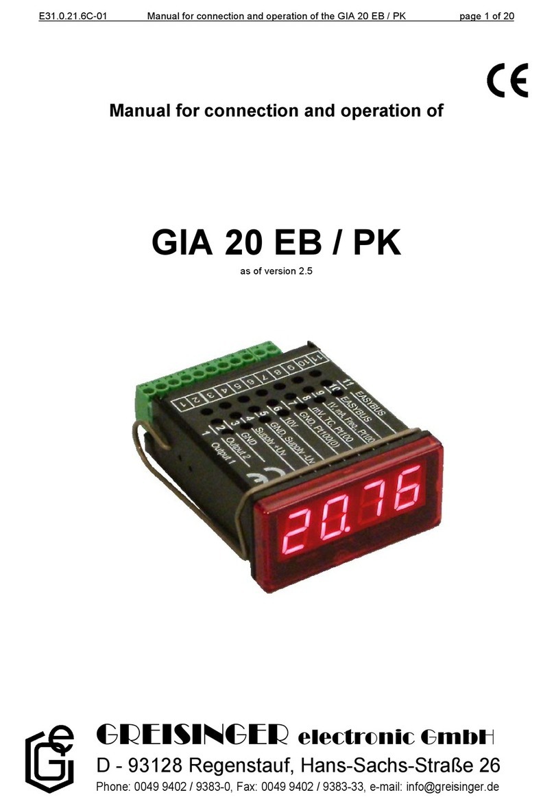
GREISINGER electronic
GREISINGER electronic GIA 20 EB manual

Sutter Instrument
Sutter Instrument TRIO MPC-165 Series Operation manual
