EI Ei1020 User manual

1
Ei1020 & Ei1025
Installation Manual
Environmental Sensor
Read and retain carefully for as long as the product is being used.
It contains vital information on the installation of this product. This
manual should be regarded as part of the product.
Contents
Page
1. Introduction 2
2. Product Overview 2
3. Technical Specications 3
4. Installation 4
5. RF Communication 6
6. Guarantee 6
7. Contact us 8
P/N B20481 Rev1© Ei Electronics 2021

2
Models Sensor Type
Ei1020 Temperature and Humidity Sensors
Ei1025 Carbon Dioxide, Temperature and Humidity Sensors
70mm
70mm 34mm
Introduction
The Ei1020 and Ei1025 are Environmental Sensors for indoor use. They
measure CO2 levels (Ei1025 only), temperature and humidity. They are
wireless and powered by a non-replaceable lithium battery. Any data
collected by the sensors is uploaded via the SmartLINK Gateway to a
portal where the information is displayed.
The Environmental Sensor must be installed in accordance with the
instructions given in this manual.
Any use other than that described in this manual is seen as unintended
use.
Please read the manual in full before installing the Environmental
Sensor.
Product Overview

3
1. Obstructions of any sort will result in a reduction in range from the free
space specification. The range may vary depending on installation.
2. Temperature and humidity conditions are for normal operation and
storage. Units will function outside these ranges as required by the specific
product Standards. Extended exposure to conditions outside these ranges
can reduce product life. For advice on prolonged operation outside these
ranges consult the manufacturer.
Technical Specification
Power supply 3V Lithium Battery (non-replaceable)
RF frequency 868.2MHz band (1% duty cycle)
RF Range >100 Metres in free air1
Receiver category 2
Typical RF power 8.1 dBm
Max RF power +14 dBm
Data upload Via the Ei1000G Gateway
Fixings Supplied with screws, wall plugs and
mounting bracket
Operating
& Storage
Temperature range
-10°C to 40°C
Operating &
Storage Humidity
range
15% to 95% Relative Humidity2
(non-condensing)
Dimensions 70mm x 70mm x 34mm
Weight Ei1020: 74g Ei1025: 81g
Approvals RF performance to EN 300 220-1 in
accordance with EN 300 220-2
EMC performance to EN 301 489-1 in
accordance with EN 301 489-3
Safety to EN 62368-1

4
Installation
IMPORTANT: A SmartLINK Gateway must be present and fully
operational in the dwelling.
IMPORTANT: To install the Environmental Sensor, you must have
access to that Gateway in the SmartLINK app.
Location
The sensors can be installed in any room. However, some of the information
the sensors collect is room specific as detailed in the table below:
Ensure when installing the Environmental Sensors, that the location
selected is appropriate to the information sought.
The sensors are designed to be wall/ceiling mounted:
a. At approximately 1.4m from the floor level (for wall mounting)
b. At least 300mm from any walls or corners where there is dead air.
c. At least 300mm from any obstructions (eg. light fitting, decorative
object, furniture, curtains, etc...)
d. in free space.
Do NOT install:
a. Next to or directly above sources of Heat (such as cookers, heaters,
etc…).
b. Next to or directly above air conditioning vents, windows, wall
vents, etc…
c. In areas where it may be exposed to water splashes, dripping or
condensation (e.g. sink, above an electric kettle, etc…).
d. In direct sunlight.
Ei1020 Ei1025 Notes
Allergens Risks Allergens Risks Sensor must be
installed in Living Room
Cold Home Risk Cold Home Risk
Sensor must be
installed in Living
Room or Bedroom
Damp & Mould Risk Damp & Mould Risk
Excess Heat Risk Excess Heat Risk
Sensor must be
installed in Living
Room, Kitchen,
Hallway or Bedroom
Heat Loss Risk Heat Loss Risk
Abandonment Risk
Indoor Air Quality
Risk
Ventilation Risk

5
Mounting
WARNING: to prevent injury, this device must be securely attached
to the wall or ceiling in accordance with the installation instructions.
Remove the mounting bracket
from the packaging.
Place the mounting bracket exactly
where you want to mount the
sensor. With a pencil, mark the
location of the two screw holes.
Taking care to avoid any electrical
wiring, drill holes using a 5.0mm
drill bit through the centre of the
marked locations. Push the plastic
screw anchors provided into the
drilled holes. Screw the mounting
bracket to the wall/ceiling (see
figure 2).
IMPORTANT: Make sure the mounting bracket is positioned so that
the text is at the top.
Adding the Environmental Sensor
to the Gateway System
Open your SmartLINK App available to download from the Google Play
or iTunes app store and simply follow the steps in the SmartLINK App.
Figure 2

6
RF Communication
Ei Electronics radio communication systems are very reliable and
are tested to high standards. However, due to their low transmitting
power and limited range (required by regulatory bodies) there are
some limitations to be considered.
Receivers may be blocked by radio signals occurring on or near their
operating frequencies.
The numbers of walls, ceilings and metal objects in the signal path can
also reduce the strength of the signal.
If you get an error and the Environmental Sensor does not register
with the Gateway, try a different location. If the problem persists,
please contact us at the nearest address at the end of this manual.
Guarantee
Ei Electronics guarantees this device for five years from the date
of purchase against any defects that are due to faulty materials or
workmanship.
This guarantee only applies to normal conditions of use and service
and does not include damage resulting from accident, neglect, misuse,
unauthorised dismantling, or contamination howsoever caused. This
guarantee excludes incidental and consequential damage.
This guarantee does not apply to any product that has been modified in
any way by a third party or has been fitted with a third-party element.
Do not interfere with this device or attempt to tamper with it. This will
invalidate the guarantee and may result in malfunction.
This guarantee is in addition to your statutory rights as a consumer.
If this device should become defective within the guarantee period,
then contact us.
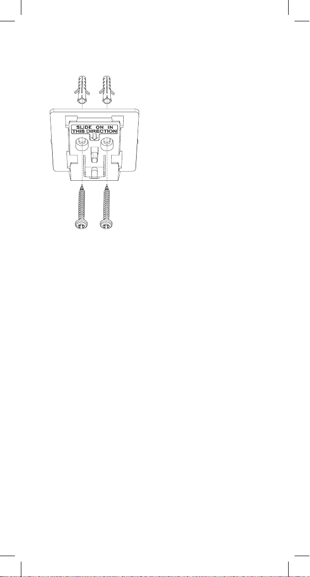
If you are advised to return your Environmental Sensor to us, please
ensure to separate it from the mounting bracket, place it in a padded
box, with the proof of purchase and a note stating the nature of the
fault.

7
The crossed out wheelie bin symbol that is on your
product indicates that this product should not be disposed
of via the normal household waste stream. Proper
disposal will prevent possible harm to the environment or
to human health. When disposing of this product please
separate it from other waste streams to ensure that it can
be recycled in an environmentally sound manner. For
more details on collection and proper disposal, please
contact your local government office or the retailer where
you purchased this product.
Block E1
0889
Hereby, Ei Electronics declares that these Ei1020 / Ei1025 Sensors are
in compliance with the essential requirements and other relevant
provisions of Directive 2014/53/EU. The Declaration of Conformity
may be consulted at
www.eielectronics.com/compliance
Hereby, Ei Electronics declares that these Ei1020 / Ei1025 Sensors are
in compliance with the essential requirements of the Radio Equipment
Regulations 2017. The Declaration of Conformity may be consulted at
www.eielectronics.com/compliance

8
Aico Ltd
Maesbury Road
Oswestry
Shropshire SY10 8NR
Telephone: 01691 664100
www.aico.co.uk
Ei Electronics
Shannon Industrial Estate,
Shannon, V14 H020, Co.Clare, Ireland.
Telephone: +353 (0)61 471277
www.eielectronics.com
Contact Us
This manual suits for next models
1
Table of contents
Popular Accessories manuals by other brands

Dini Argeo
Dini Argeo DFW Series user manual

Gastro-Cool
Gastro-Cool Slimline GCDC130 Instructions for use

idronaut
idronaut Ocean Seven 304Plus Operator's manual

HikRobot
HikRobot SC2000E Mini Series quick start guide

Teledyne Lecroy
Teledyne Lecroy CP031 instruction manual

McCue
McCue Goal Post installation instructions