EI QVT User manual

Phone:(910) 392‐2490
Fax: (910) 392‐2123
416 Landmark Drive
Wilmington, NC 28412 www.easterninstruments.com
QVT MULTIVARIABLE TRANSMITTER
QVT
INSTALLATION & OPERATION
MANUAL
REV 8/22
REVISION VERSION 1.0.51
ORIGINAL LANGUAGE
Copyright© 2022 Eastern Instrument Laboratories, Inc.
All Rights Reserved.

2
Phone:(910) 392‐2490
Fax: (910) 392‐2123
416 Landmark Drive
Wilmington, NC 28412 www.easterninstruments.com
TABLE OF CONTENTS
SAFETY
Safe Operaon................................................................................................................. 3
INTRODUCTION
The QVT Mulvariable Transmier................................................................................ 4
GETTING TO KNOW THE QVT
Exploded View of the QVT Transmier.......................................................................... 5
QVT Transmier Schemac............................................................................................ 6
Close‐Up of the IO Board ‐Wiring Terminals ................................................................. 7
Close‐Up of the Processor Board/LCD Board ................................................................. 7
QUICK START UP GUIDE ........................................................................................................... 8
BOOT SEQUENCE ...................................................................................................................... 9
MECHANICAL INSTALLATION
Mechanical Installaon: Mounng the QVT ................................................................ 10
Tubing the QVT.............................................................................................................. 14
ELECTRICAL INSTALLATION
Accessing the Wiring Connectors of the QVT............................................................... 16
Using the Wiring Connectors ........................................................................................ 17
Wiring the QVT .............................................................................................................. 18
4‐20 mA Loop Power................................................................................................... 19
RTD Temperature Sensor Input .................................................................................. 21
OPTIONS
Purge System (Oponal) ............................................................................................... 23
Using the 3‐Way Valve .................................................................................................. 25
GETTING TO KNOW YOUR LCD SCREEN................................................................................. 26
PROCEDURES
Changing the Ae Number.............................................................................................. 27
Changing the EFS (Electronic Full Scale) ...................................................................... 28
Changing the Units of Measure .................................................................................... 29
Zero DP1 Differenal Pressure Measurement ............................................................. 30
Zero Process Temperature............................................................................................ 32
Revert to Factory Sengs (Factory Restore) ............................................................... 34
QVT SPECIFICATIONS.............................................................................................................. 35
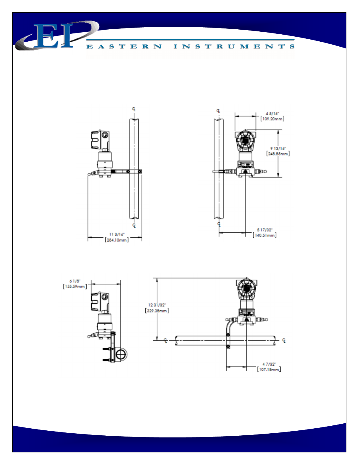
DIMENSIONAL DRAWINGS..................................................................................................... 39

3
Phone:(910) 392‐2490
Fax: (910) 392‐2123
416 Landmark Drive
Wilmington, NC 28412 www.easterninstruments.com
PLEASE READ BEFORE OPERATING YOUR NEW MULTIVARIABLE TRANSMITTER
For personal/system safety as well as for opmum performance reasons, please read and
understand this manual before working with the transmier.
Check for damaged parts before operang the transmier. Any damaged part should be
properly repaired or replaced by trained personnel. Do not operate the transmier if any
component does not appear to be funconing correctly. Contact Eastern Instruments for
assistance or for repair components.
Ensure that only trained personnel perform installaon of the transmier.
Ensure that assembly of the transmier to a flange or manifold of some kind is done
properly as improper assembly could lead to damage of the sensors of the transmier or
could render the transmier dangerous. Failure to follow the installaon guidelines with‐
in this manual could cause serious injury or death.
If the transmier is installed in a high‐voltage environment, it is possible that a fault or in‐
stallaon error could cause high voltage to be present on the transmier leads and termi‐
nals. Electrical shock could cause serious injury or death.
Use only replacement components or installaon bolts supplied by Eastern Instruments as
non‐approved components or installaon hardware may render the transmier danger‐
ous and could lead to serious injury or death.
For Technical Assistance, please contact us:
Eastern Instruments
416 Landmark Drive
Wilmington, NC 28412
SAFETY
SAFE OPERATION

4
Phone:(910) 392‐2490
Fax: (910) 392‐2123
416 Landmark Drive
Wilmington, NC 28412 www.easterninstruments.com
THE QVT MULTIVARIABLE TRANSMITTER
The QVTTM Mulvariable Transmier from Eastern Instruments is a Smart Transmier that can
be used for the accurate measurement of up to four separate process variables including
Differenal Pressure, Temperature and Absolute Pressure. When coupled with any DP based
flow measurement element, the QVTTM will calculate the fully compensated mass flow of air/
gas travelling through any process which is at or near atmospheric pressure (5 ‐25 psia). The
QVT will accept a Process Temperature signal from an external RTD and will simultaneously
measure the Differenal Pressure and Absolute Pressure from a coupled flow element. The
QVT will be as accurate whether coupled with an Eastern Instruments flow element or wheth‐
er it is coupled with a flow element from the manufacturer of your choosing. Using these in‐
puts, the QVT will calculate a compensated mass flow rate and will give an output proporonal
to this compensated mass flow rate via a 4‐20 mA signal. Please note that the 4‐20 mA signal
can be fully compensated (live measurement of DP, AP and Temperature), parally compen‐
sated (live measurement of DP only) or the values for the Process Variables (DP, AP or Tem‐
perature) can be output via the 4‐20 mA signal as well.
INTRODUCTION

5
Phone:(910) 392‐2490
Fax: (910) 392‐2123
416 Landmark Drive
Wilmington, NC 28412 www.easterninstruments.com
Exploded View of QVT Transmier
GETTING TO KNOW THE QVT

6
Phone:(910) 392‐2490
Fax: (910) 392‐2123
416 Landmark Drive
Wilmington, NC 28412 www.easterninstruments.com
QVT Transmier Schemac ‐Shown with oponal 3‐Valve Manifold and Purge System
3‐Valve Manifold
(Recommended Accessory)

7
Phone:(910) 392‐2490
Fax: (910) 392‐2123
416 Landmark Drive
Wilmington, NC 28412 www.easterninstruments.com
Close‐up of the IO Board ‐Wiring Terminals
Close‐up of the Processor Board/LCD Board
The 4‐20 mA Connector The RTD Connector
Board Snap Mounts
Snap Mounng Holes
Snap Mounng Holes

8
Phone:(910) 392‐2490
Fax: (910) 392‐2123
416 Landmark Drive
Wilmington, NC 28412 www.easterninstruments.com
VERIFY PROPER MECHANICAL INSTALLATION
Verify that the QVT is properly mounted (See “Mechanical Installaon: Mounng
the QVT” secon of the QVT I&O Manual for Addional Info)
Verify that the High and Low Ports of your flow element are properly tubed to the
transmier/manifold/purge system (See “Tubing the QVT” secon of the QVT I&O
Manual for Addional Info)
VERIFY PROPER WIRING OF THE QVT
Verify that the proper power has been supplied to the QVT (See “Wiring the QVT: 4
‐20 mA Loop Power” secon of the QVT I&O Manual for Addional Info)
If using an RTD to measure the process temperature, verify that the RTD is properly
wired (See “Wiring the QVT: RTD Temperature Sensor Input” secon of the QVT
I&O Manual for Addional Info)
PERFORM ZERO OF THE DP1 DIFFERENTIAL PRESSURE
(See “Procedures: Zero DP1 Differenal Pressure Measurement” secon of the
QVT I&O Manual for Addional Info)
VERIFY COMMUNICATION (4‐20 mA OUTPUT)
Compare the readings on your PLC/DCS with the values of the output variable
shown of the QVT screen. (Example: 0 lb/hr on the QVT would equate to 4 mA of
output)
QUICK START UP GUIDE

9
Phone:(910) 392‐2490
Fax: (910) 392‐2123
416 Landmark Drive
Wilmington, NC 28412 www.easterninstruments.com
Aer powering on the QVT, the transmier will proceed through a boot sequence followed by
an automated scrolling of key values and sengs within the QVT.
BOOT SEQUENCE
AUTO SCROLL SEQUENCE
Manual Scrolling of the displays shown in the Auto Scroll Sequence is possible by pressing the
“PRG” Buon repeatedly unl the desired display is shown. The display will be shown for ap‐
proximately 2 hrs before returning to the Auto Scroll Sequence.
BOOT SEQUENCE
Upon Boot/Reboot the so‐
ware version (le) will be
displayed, followed by a
Pass/Fail screen denong
whether the soware has
loaded properly (right). Up‐
on a successful Boot (Pass),
the Auto Scroll Sequence
(below) will begin.
Upon a successful Boot Se‐
quence (Above), the Auto
Scroll Sequence will begin.
Each value will be shown
sequenally for 1.5 seconds
each. Upon compleon, the
sequence will start over
again automacally.
dP Display
Temperature Display 4-20 mA Full ScaleMass Flow Display
AP Display

10
Phone:(910) 392‐2490
Fax: (910) 392‐2123
416 Landmark Drive
Wilmington, NC 28412 www.easterninstruments.com
MECHANICAL INSTALLATION: MOUNTING THE QVT
The QVT can either be mounted via an oponal mounng bracket which allows the transmier
to be mounted to either a vercal or horizontal 2” pipe, or, if the transmier is purchased with
flow elements from Eastern Instruments, the transmier will be mounted directly to the flow
element (VAP Pitots, DSV Duct Secon or HBP High Beta Flow Condioner). Detailed dimen‐
sional drawings are included within this secon of the manual. The suggested installaon lo‐
caon depends upon the process, but in general, for air and gas flow measurement, the trans‐
mier is suggested to be located above the tap for the air/gas flow measurement so that con‐
densate that may collect in the impulse lines, can drain away from the transmier.
MECHANICAL INSTALLATION
Mount Bracket for QVT: Pipe Mount Mount Bracket for QVT w/ Manifold: Pipe Mount
Mount Bracket for QVT: Panel Mount Mount Bracket for QVT w/ Manifold: Panel Mount
5/16” x 1.75” Bolt For
QVT Mounng
1 1/2” Size U‐Bolt
For Pipe Mounng
1 1/2” Size U‐Bolt
For Pipe Mounng
M8 x 1.25 For Transmier
Manifold Mounng
5/16” x 1.75” Bolt For
QVT Mounng
5/16” x 1.75” Bolt For
Panel Mounng
M8 x 1.25 For Transmier
Manifold Mounng
5/16” x 1.75” Bolt For
Panel Mounng

11
Phone:(910) 392‐2490
Fax: (910) 392‐2123
416 Landmark Drive
Wilmington, NC 28412 www.easterninstruments.com
Vercal Pipe Mount ‐Transmier Only
Horizontal Pipe Mount ‐Transmier Only
12
Phone:(910) 392‐2490
Fax: (910) 392‐2123
416 Landmark Drive
Wilmington, NC 28412 www.easterninstruments.com
Vercal Pipe Mount ‐Transmier and 3‐Way Valve Manifold
Horizontal Pipe Mount ‐Transmier and 3‐Way Valve Manifold

13
Phone:(910) 392‐2490
Fax: (910) 392‐2123
416 Landmark Drive
Wilmington, NC 28412 www.easterninstruments.com
Vercal Pipe Mount ‐Transmier, 3‐Way Valve Manifold and Purge System
Horizontal Pipe Mount ‐Transmier, 3‐Way Valve Manifold and Purge System

14
Phone:(910) 392‐2490
Fax: (910) 392‐2123
416 Landmark Drive
Wilmington, NC 28412 www.easterninstruments.com
TUBING THE QVT
Process Connecons are made to the boom of the QVT via 1/4” NPT female connecons on 2
1/8” Centers. Please note that if the oponal 3‐Way Valve or the Purge System were pur‐
chased, the Process Connecons will vary. These connecons can be modified to accept mani‐
folds on 2”, 2 1/8” and 2 1/4” centers by using an oponal adapter flange.
It is recommended that the tubing used to connect the QVT to your flow element be at least
3/8” hard walled Stainless Steel or Copper Pipe if using the oponal Purge System. Please see
the accompanying table in the “Purge System” secon of this manual for specifics on the rec‐
ommended diameter of tubing versus the run length of the pipe.
Please note that the connecons will differ depending on whether you are connecng directly
to the QVT, via a 3‐way valve or via the TMP transmier purge. The connecons for each of
these three scenarios are illustrated below.
QVT Transmier Process Connecons

15
Phone:(910) 392‐2490
Fax: (910) 392‐2123
416 Landmark Drive
Wilmington, NC 28412 www.easterninstruments.com
QVT Transmier with 3‐Way Valve Process Connecons
QVT Transmier with 3‐Way Valve and TMP Purge System Process Connecons

16
Phone:(910) 392‐2490
Fax: (910) 392‐2123
416 Landmark Drive
Wilmington, NC 28412 www.easterninstruments.com
ELECTRICAL INSTALLATION
ACCESSING THE WIRING CONNECTORS OF THE QVT
NOTE: POWER MUST BE OFF BEFORE REMOVING
THE COVER OF THE QVT!
REMOVING THE LCD BOARD
1. Once power has been turned offto the trans‐
mier, remove the cover to expose the Processor
Board or LCD Circuit Board. Once the cover has
been removed, your QVT should look similar to
the picture #1 on the right.
2. Remove the Processor Board or LCD Circuit
Board. To remove the board, press on the
boom and pull out at the top behind the circuit
board as seen in picture #2. DO NOT PULL ON
THE OVERLAY AS IT COULD BE DAMAGED.
3. Carefully remove the board as shown in picture
#3.
REPLACING THE LCD BOARD
1. Align the Board Snap Mounts with the Snap
Mounng Holes on the LCD Board
2. With fingers over the snap mounts press the
board into place as in picture #4. The Board Snap
Mounts should snap into the Snap Mounng
Holes.
3. Please note that the Board has four holes and
there are only two Board Snap Mounts. This ena‐
bles the board to be rotated to any of four posi‐
ons depending on the desired orientaon of the
LCD screen. Please see picture #5 for reference.
4. Check the wiring to ensure that the internal wir‐
ing clears prior to snapping the board into place.
5. Replace the cover of the QVT.
#1
#2
#3
#4
#5

17
Phone:(910) 392‐2490
Fax: (910) 392‐2123
416 Landmark Drive
Wilmington, NC 28412 www.easterninstruments.com
USING THE WIRING CONNECTORS
Male Locking Latch
Electrolyc Copper (E‐Cu)
Tin‐Plated Contact Bridge
Female Locking Latch
Gripping Plate with
Sliding Connector Release
Straight or Angled, E‐CU, n‐plated
solder pins for both wave and THR soldering
Push‐Buon
Test Port
High‐Alloy Stainless Steel (CrNi)
Clamping Spring
Original Size:
3.5 mm Pin Spacing
Male Header
Female Connector Wire Gauge: 24 – 14 AWG
Strip Length: 8 – 9 mm
Gripping Plate
Sliding Connector
Release
Connecng/Disconnecng Male Header and
Female Connector
To Disconnect: Press down on the Sliding
Connector Release (towards the Male Head‐
er) and pull on the Gripping Plate to release
Female Connector from Male Header.
To Connect: Push the Female Connector into
the Male Header unl you hear a click.
Inserng and Removing Conductors
from Connector
To Insert: Using the supplied screwdriver,
press down on the Push Buon and insert
the wire into the terminal.
To Remove: Press the Push Buon and
pull upwards on the wire to remove the
wire from the Female Connector.
Push‐Buon
Insert Wire
Here
Included
Screwdriver

18
Phone:(910) 392‐2490
Fax: (910) 392‐2123
416 Landmark Drive
Wilmington, NC 28412 www.easterninstruments.com
WIRING THE QVT
There are two parts to wiring the QVT. For all versions of the QVT, 4‐20 mA loop power must
be supplied. For mulvariable transmiers in which Process Temperature will be measured,
an RTD must also be wired to the QVT. The wiring connecons for both the 4‐20 mA loop
power and the RTD inputs are located behind the LCD circuit board inside the head of the
transmier. Once the LCD Board has been removed, the connectors for both the 4‐20 mA
loop power and the RTD can be wired. You can wire the connectors by either removing the
female connector from the board, adding the wire externally and replacing the female con‐
nector into the male header already wired, or you can leave the female connector seated in
the male header and wire it in place or internally.
NOTE: ALWAYS REMOVE POWER TO THE QVT BEFORE REMOVING THE LCD BOARD AND ON‐
LY RESTORE POWER AFTER THE LCD BOARD HAS BEEN RETURNED TO ITS PLACE!
Please note the color indicators at the boom of the customer connecon wiring terminals
for both the 4‐20 mA Connector and the RTD Connector. The following pages offer a more
detailed descripon of the proper wiring for each of these connecons.
The 4‐20 mA Connector The RTD Connector
Board Snap Mounts

19
Phone:(910) 392‐2490
Fax: (910) 392‐2123
416 Landmark Drive
Wilmington, NC 28412 www.easterninstruments.com
4‐20 MA LOOP POWER:
An example of loop wiring is shown below. We have assumed that we used 5000 feet of
Belden 88760 twisted, 18 AWG shielded pair, 7.5 ohm/1000 conductor. The Receiver and A/
D data logger both have a 250 Ωresistor. The power supply is assumed to be a +/‐10%, 24 vDC
source, with the negave terminal grounded, which is shared with other loops. The minimum
voltage expected is the 24 x 0.9 = 21.6 v DC. NOTE: POWER SUPPLY SHOULD BE A GOOD
QUALITY ISOLATED POWER SUPPLY.
+
‐
LOOP POWERED
RECEIVER
The internal connector’s polarity is
color coded as shown
+
‐
SIGNAL COMMON
QVT Transmier
+
‐
24 vDC
POWER
5000
+ ‐
A/D System
The Shield is grounded only
on the power supply end!
QVT Transmier
POWER
SUPPLY
+
‐
RECEIVER
IN SERIES
OR
PARALLEL
Type 2‐2 Wire Circuit
+
‐
SIGNAL
COMMON
The 4‐20 mA loop transmier in the QVT
is a TYPE 2‐2 Wire Circuit as defined in
ANSI/ISA‐50.00.01‐1975 (R2012) as
shown in the sketch (right) and is
assumed to have the negave terminal
of the power supply grounded.
Typical Calculaon Based on 5,000 feet of Cable
Descripon Length () Ω/ΩmA FS Volt Drop
Transmier Minimum Drop 8.8
Posive Cond. 5000 0.0075 37.5 20 0.75
Negave Cond. 5000 0.0075 37.5 20 0.75
Loop Powered Receiver 250 20 5
A/D Data Logger 250 20 5
Total 575 20.3

20
Phone:(910) 392‐2490
Fax: (910) 392‐2123
416 Landmark Drive
Wilmington, NC 28412 www.easterninstruments.com
Be sure to check your load resistance in the output current loop as too high a load resistance
will cause malfuncon or incorrect operaon of the QVT transmier. Below are two methods
of determining whether the load resistance exceeds the allowable operaonal limit.
Voltage Drop: The minimum transmier voltage as seen in the chart below, is 8.8 V. The re‐
sistance values of the conducve elements are mulplied by the current to give the voltage
drop of each element. Sum the voltage drops for all conducve elements along with the mini‐
mum transmier voltage and compare that value with the minimum power supply voltage. If
the total is less than the minimum power supply voltage, the load is OK.
Summing Resistances: Sum the resistances of all circuit elements. Find where the total,
summed resistance total intersects the supply voltage in the below graph. Compare the value
for supply voltage that you found on the graph with your minimum power supply voltage. If
the value from the chart is lower than the minimum power supply voltage, the load is OK.
Load Resistance, OHM
Supply Voltage, vDC
Table of contents


