3. INTRINSIC SAFETY CERTIFICATION
3.1 ATEX certificate
The BA374C has been issued with an EC-Type
Examination Certificate number
BAS02ATEX1185X by EECS showing compliance
with the European ATEX Directive 94/9/EC for
Group II, Category 1 gas atmospheres, EEx ia IIC
T5. The instrument bears the Community Mark
and, subject to local codes of practice, may be
installed in any of the European Economic Area
(EEA) countries. i.e. Austria, Belgium, Denmark,
Finland, France, Germany, Greece, Ireland, Italy,
Luxembourg, The Netherlands, Norway, Portugal,
Spain, Sweden and the United Kingdom. ATEX
certificates are also accepted in Norway, Iceland,
Liechtenstein, Switzerland and the Czech Republic
This manual describes installations which conform
with BS EN60079: Part 14:1997 Electrical
Installation in Hazardous Areas. When designing
systems for installation outside the UK, the local
Code of Practice should be consulted.
3.2 Other intrinsic safety certifications
Please contact BEKA for a list of non-European
intrinsic safety approvals.
3.3 Zones, Gas Groups and T rating
The BA374C and accessories have been certified
EEx ia IIC T5. When connected to an approved
system the transmitter may be installed in:
Zone 0 explosive gas air mixture
continuously present.
Zone 1 explosive gas air mixture likely
to occur in normal operation.
Zone 2 explosive gas air mixture not
likely to occur, and if it does,
it will only exist for a short time.
Be used with gases in groups:
Group A propane
Group B ethylene
Group C hydrogen
Having a temperature classification of:
T1 450oC
T2 300oC
T3 200oC
T4 135oC
T5 100oC
This allows the BA374C to be installed in all Zones
and to be used with most common industrial gases
at ambient temperatures between -40 & +60oC.
Note: minimum operating temperature -20oC.
3.4 Certification information label
The certification information label is fitted on the
top outside surface of the enclosure. The
instrument serial number and date of manufacture
are shown on a separate label inside the
enclosure.
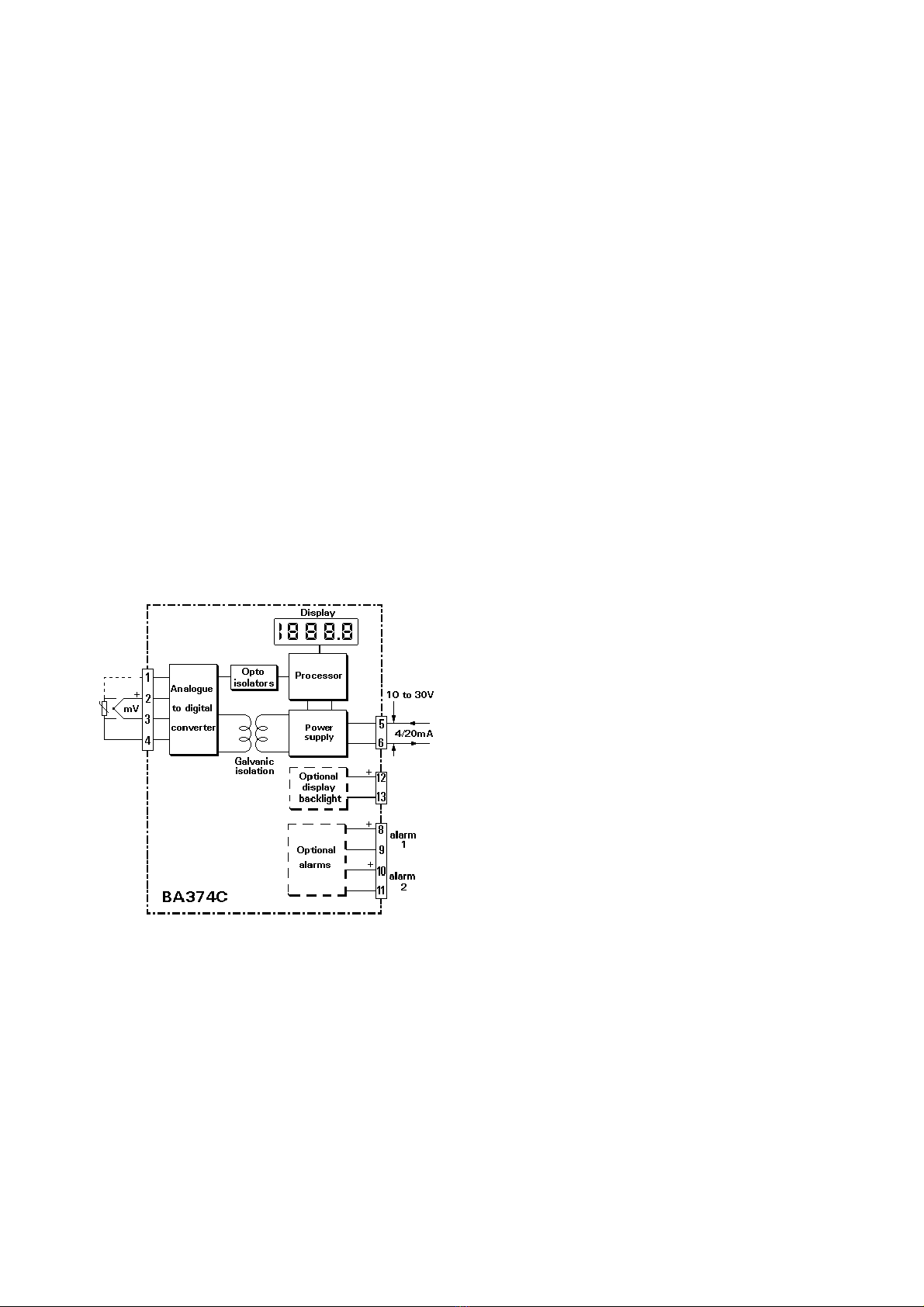
3.5 Input terminals 1, 2, 3 & 4
When the BA374C is installed in a hazardous area
the input terminals may be connected to any
floating or earthed sensor complying with the
requirements for simple apparatus as defined in
Clause 5.4 of EN50020:1994. i.e. the sensor
generates less than 1.5V, 100mA, or 25mW.
Thermocouples and resistance thermometers are
simple apparatus and any floating or earthed
device may be connected to the BA374C,
providing that both are installed within the
hazardous area.
The permitted maximum parameters for the cables
connecting the transmitter to the sensor are 4µF
and 9.2mH in the most onerous gas group IIC
(hydrogen). These are large and are very unlikely
to be exceeded on any thermocouple or resistance
thermometer installation.
If the transmitter input is to be connected to a
device which does not comply with the
requirements for simple apparatus, a system
certificate should be obtained, or the safety of the
system assessed using the entity concept. The
certified safety description of the BA374C input
terminals is:
Uo = 8.61V
Io = 62mA dc
Po = 0.14W
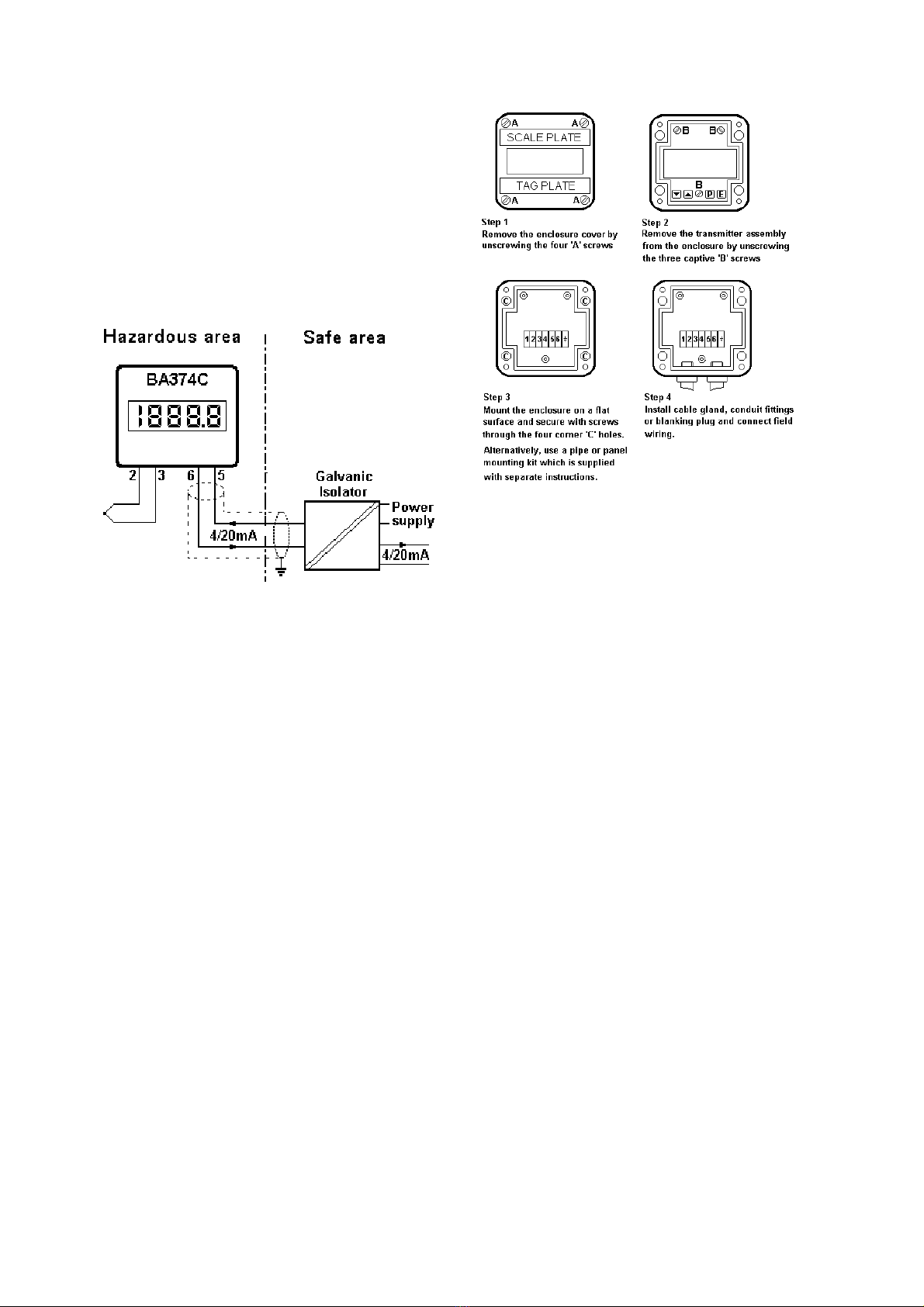
3.6 4/20mA output - terminals 5 & 6
The BA374C transmitter is powered via these
terminals, and the current drawn is the 4/20mA
output signal. The transmitter is normally powered
from the safe area so a Zener barrier or galvanic
isolator is required to protect the circuit. Any
single channel Zener barrier or galvanic isolator
6