ei3 Amphion S14 Series User manual

Amphion S14
S14-H (green box)
S14-N (red box)
S14-C (black box)
User Guide
ei3Part Numbers
IAA-254-H-S14
IAA-30-N-S14
IAA-30-C-S14
© 2019 ei3 Corporation
Version 2.0

Amphion User Guide
Page 2 of 26
Contents
Important Information .............................................................................................. 3
Specifications............................................................................................................. 4
Amphion S14-H (RSSD, green box)....................................................................... 4
Amphion S14-N (MRFD, red box)......................................................................... 4
Amphion S14-C (black box) .................................................................................. 4
Electrical ............................................................................................................... 6
Grounding ............................................................................................................. 6
Networking ........................................................................................................... 7
Machine LAN (S14-N or S14-C) ............................................................................. 7
Internet (S14-H or S14-C)...................................................................................... 7
USB Port................................................................................................................ 7
S14 Physical Specifications.................................................................................... 8
Optional Wall Plug Power Supply ......................................................................... 8
Optional microSD Card ......................................................................................... 8
Terminations......................................................................................................... 9
Amphion Wiring and Placement.............................................................................. 11
Operating the Amphion........................................................................................... 12
Amphion Project and Serial Numbers................................................................. 12
Configuration ...................................................................................................... 13
1. Configuration using a USB drive................................................................. 14
2. Configuration using the Web interface ...................................................... 15
Installation and Operation.................................................................................. 19
Troubleshooting ...................................................................................................... 20
Yellow LED: Power ......................................................................................... 20
Green LED: System......................................................................................... 20
Blue LED: Tunnel ............................................................................................ 21
Ethernet Link Lights: ...................................................................................... 21
Troubleshooting Steps ........................................................................................ 22
IP Config Test ................................................................................................. 24
Warranty and Repair ............................................................................................... 25
Return Material Authorization............................................................................ 25

Amphion User Guide
Page 3 of 26
Important Information
Safety: These instructions must be followed.
THE USE OF THIS DEVICE IS SUBJECT TO THE TERMS AND CONDITIONS OF
PURCHASE.
IT IS THE RESPONSIBILITY OF THE USER TO ENSURE THAT ALL LOCAL SAFETY CODES
ARE OBSERVED DURING THE USE OF THE AMPHION S14 DEVICE. IN PARTICULAR
BUT NOT LIMITED TO, THE USER MUST OBSERVE ALL CODES PERTAINING TO
PERSONNEL SAFETY WITH RESPECT TO REMOTE MONITORING AND ADJUSTMENT
OF EQUIPMENT.
Liability: The user assumes all liability when using the Amphion device.
EI3 CORPORATION ASSUMES NO RESPONSIBILITY OR LIABILITY RESULTING FROM
THE USE OF THE AMPHION S14 DEVICE. EI3 CORPORATION IS NOT LIABLE FOR
DAMAGES CONSEQUENTIAL OR OTHERWISE THAT MIGHT OCCUR FROM THE USE
OR MIS-USE OF THE AMPHION S14.
This device should only be used with ei3Corporation approved applications and incorporates
technology protected by US Patent # 7,054,919.
Informations importantes
Sécurité: Ces instructions doivent être suivies:
L'UTILISATION DE CE DISPOSITIF EST SOUMISE AUX TERMES ET CONDITIONS
D'ACHAT.
IL EST DE LA RESPONSABILITÉ DE L'UTILISATEUR DE S'ASSURER QUE TOUS LES
CODES DE SÉCURITÉ LOCAUX SONT RESPECTÉS PENDANT L'UTILISATION DU
AMPHION S14. EN PARTICULIER, MAIS SANS S'Y LIMITER, L'UTILISATEUR DOIT
RESPECTER TOUS LES CODES RELATIFS À LA SÉCURITÉ DU PERSONNEL EN MATIÈRE
DE SURVEILLANCE A DISTANCE ET AJUSTEMENT DE L'ÉQUIPEMENT.
Responsabilité: L'utilisateur assume tous les risques lors de l'utilisation du dispositif Amphion.
EI3 CORPORATION N'ASSUME AUCUNE RESPONSABILITÉ RESULTANTE DE L'UTILISATION DE
L'APPAREIL AMPHION S14. EI3 CORPORATION N'EST PAS RESPONSABLE DES DOMMAGES
INDIRECTS OU AUTRES RESULTANT DE LA BONNE OU DE LA MAUVAISE UTILISATION DE
L'APPAREIL AMPHION S14.
!
!

Amphion User Guide
Page 4 of 26
Specifications
Amphion S14-H (RSSD, green box)
The ei3Amphion S14-H is also known as a Remote Service Security
Device (RSSD) or simply the “green box”, because of its identifying
green trim. It contains a firewall and router to provide a single,
private, encrypted connection for a factory to securely connect any
or all its machines to the ei3cloud. This device is used for
installations with multiple machines in one facility.
Amphion S14-N (MRFD, red box)
The ei3Amphion S14-N is also known as a Machine Router Firewall
Device (MRFD), or simply the “red box” because of its identifying
red trim. It contains firewall and network address translation
capabilities to securely connect a machine or integrated line to the
ei3cloud via the Amphion S14-H, while isolating them from
everything else within the facility and vice versa. The S14-N can
collect, analyze, transmit, and act upon its machine’s data. It has
capability for user installation of a microSD card, for optionally
caching or storing its machine data locally.
Amphion S14-C (black box)
The ei3Amphion S14-C is also known as the “black box” because of
its identifying black trim. It combines the functionality of both the
S14-H and S14-N devices and is used only for single machine
installations in a facility. The S14-C may not be used with either S14-
H or S14-N. The S14-C can collect, analyze, transmit, and act upon
its machine’s data. It has capability for user installation of a microSD
card, for optionally caching or storing its machine data locally.

Amphion User Guide
Page 5 of 26
Figure 1: Amphion Model 14-H and 14-N devices arranged in a typical multiple
machine installation configuration

Amphion User Guide
Page 6 of 26
Electrical
The Amphion S14 is designed to be connected to a regulated 24VDC
power source and deployed within a Limited Energy Circuit to
protect the Amphion device and wiring. The power should be
connected to the power terminals according to the terminal
drawing supplied in the Installation Section of this manual.
Main Power: 24VDC, 10W
Grounding
The Amphion S14 case is grounded and the electronic circuit is
isolated. Proper installation requires the use of minimum CAT-5
shielded Ethernet cable with a shielded head that is also grounded.
The user is responsible to make sure the Amphion case and shielded
cables are properly grounded, either via a grounded DIN rail or by
other means.
Figure 2: Grounding of Amphion S14 and shielded Ethernet cable

Amphion User Guide
Page 7 of 26
Networking
The Amphion is designed to accommodate a wide variety of
networking requirements. There are two isolated networking ports
on the Amphion; they are labeled “To ei3”and “To Machine” on all
S14 models H, C and N.
Machine LAN (S14-N or S14-C)
Physical Type: 10/100/1000 Mbps Ethernet
connected via RJ-45. Autosense
speed/duplex.
LAN Requirements: Private IP networks only are
supported.
Network Address Translation: 1 to 1 NAT allowed.
Number of Addresses: The Machine LAN port can support
up to an entire class-C range of IP
Addresses (254 addresses).
Internet (S14-H or S14-C)
Physical Type: 10/100/1000 Mbps Ethernet via RJ-45.
Autosense speed/duplex.
LAN Requirements: Access to Internet must be provided to
the “To ei3” port in S14-H and S14-C only.
Bandwidth: At least 56 kbps of bandwidth must be
available to this port for remote service.
Typically 4k is used for data collection.
Latency: No more than 125ms of latency should
be measured to apps.ei3.com
USB Port
The Standard USB Type A port is provided for configuring the
Amphion S14 using special configuration files produced by ei3only.

Amphion User Guide
Page 8 of 26
S14 Physical Specifications
Network Connectivity
Dual Gigabit Ethernet
Memory
4 GB onboard, up to 128 GB via microSD
CPU
Quad core 1.2 Ghz 64-bit ARM
Outside Dimensions
114 x 109 x 35 mm (4.5 x 4.3 x 1.4 inch)
Mounting
Standard DIN Rail -or- Stand-alone shelf
Weight
0.3 kg (0.6 lb)
Temperature Range
0-50 °C (32-122 °F)
Protection
IP 10 NEMA 1
Optional Wall Plug Power Supply
For customers that desire to place the Amphion in the office or IT
environment and do not have access to a 24VDC power supply, a
standard wall mounted 24VDC international power supply is
available from ei3. This includes the common plugs used in most
countries. To purchase from ei3, order item # IAA-PSU-X
Optional microSD Card
For customers who want to use the Amphion as an Industrial
Internet of Things (IIoT) edge device, the S14 has a user-accessible
microSD card slot located in the front of the device.
A microSD card is not required for the S14 to operate; a user may
insert a card to provide the ability for the S14 to cache or store data
locally when its connection to the ei3cloud is interrupted. The S14
prefers microSD cards up to 32 GB with FAT 32 or NTFS format, and
it will support up to 128 GB with NTFS format.

Amphion User Guide
Page 9 of 26
Terminations
Name
Wire Type
Connector
To
Function
To
Machine
CAT-5
network
cable
RJ-45
Machine
network
(see page 5 for
details)
The devices on this
network will be
securely accessible
To ei
3
CAT-5
network
cable
RJ-45
Network with
Internet Access
(see page 5 for
details)
Connection to the
internet for service &
monitoring
24 Power
supply +V
0.03 to 1.5
mm2
AWG 16-22
Stripped
end
24VDC power
supply
Power for device
24 Power
supply V-
0.03 to 1.5
mm2
AWG 16-22
Stripped
end
Panel ground or
earth
Wire shields

Amphion User Guide
Page 10 of 26
Figure 2: Model S14 face plate

Amphion User Guide
Page 11 of 26
Amphion Wiring and Placement
The Amphion should be installed in a dry location between 0 - 50 °C
(32 - 122 °F) for optimal performance. A limited energy circuit of 24
VDC power should be connected to the +V and V- terminals using
individual wires as per the specifications in the Terminations table
above.
For the “To ei3” port of the green and black boxes (S14-H and S14-
C), ensure that the Amphion can be provided an ethernet cable with
access to the internet.
For the “To ei3” port of the red box (S14-N), ensure that the
Amphion can be provided an ethernet cable with access to the “To
Machine” interface of the green box.
For the “To Machine” port of the green box (S14-H), ensure that the
Amphion can be provided an ethernet cable with access to the
network on which the red boxes are placed (S14-N).
For the “To Machine” port of the black and red boxes (S14-C and
S14-N), ensure that the Amphion can be provided an ethernet cable
with access to the network on which the machine devices are
located.
Every Amphion has a DIN clip at the back to make it easy to mount
onto DIN rails. If the Ethernet cables have shields, they should be
grounded via machine panel ground or other convenient location.

Amphion User Guide
Page 12 of 26
Operating the Amphion
The Amphion is an integral part of the ei3 secure network. Amphions
must be configured with information for the local internet access,
and the LAN of the equipment with which you want to connect and
collect data. The configuration process identifies the following facts
about the network environment:
•The identification of the Amphion device within the ei3
secure network,
•The method of connection to the Internet, and,
•The addresses of the equipment that is protected by the
Amphion device.
Amphion Project and Serial Numbers
The Amphion devices have a 6-digit alphanumeric serial number
that is unique to each device and does not change. When
configured, the Amphion is assigned an ei3Project number which
should be written or printed on the device label. This project
number is used to identify the Amphion within the ei3 managed
secure network for controlling access and connections to your
equipment. The project number is in the format xxxx-yy where xxxx
is an alphanumeric string that designates the facility’s Amphion
network, and yy is a number where -00 is the green box and each
subsequent number indicates an additional machine. The black box
uses -01 only.
The Amphion Serial # and
ei
3
Project # are located here

Amphion User Guide
Page 13 of 26
Configuration
Configuration of the Amphion S14 may be accomplished by one of
two methods.
1. Configuration using a USB drive
This method uses a configuration file created by an administrator in
the ei3web application and transferred to the S14 via a USB drive.
The configuration files must have the special file type “.ei3”.
2. Configuration using the Web Interface (S14-N only)
This method allows you to input the network information directly
into the Amphion device. To use this method, obtain the username
and password for the device from your ei3administrator. This
method will also allow editing of existing information in an S14-H
and S14-C after it has been previously configured using a USB drive.
The following information is needed to configure an S14:
•IP address of the S14 interface on the SFLAN or company
network
•Subnet Mask
•Default Gateway
•IP address of the S14 on the machine LAN.

Amphion User Guide
Page 14 of 26
Note: In a typical arrangement, all machine devices need to be
on the same network as “To Machine” interface of the S14-N
or S14-C.1. Configuration using a USB drive
When an S14-H and an S14-N need to be configured for the same
facility network, it is recommended to first configure and install the
S14-H, then configure and install the S14-N.
To configure an S14, follow these steps:
1. Obtain the correct “.ei3” configuration file for your S14. Contact
your ei3administrator to get the file.
2. Save the file onto an empty, FAT 32 formatted USB drive.
3. Power off the Amphion by removing the power terminal.
4. Insert the USB drive into the USB slot of the Amphion S14
5. Power on the Amphion
6. Wait up to 4 minutes to see the Success Pattern, then remove
the USB drive.The Amphion will automatically restart after the
USB drive is removed.
•Success Pattern - all four LEDs will flash on at the same time,
once per second.
•Failure Pattern – the LEDs will flash in an “X” pattern
Note: The files are digitally signed by ei3Corporation to protect
against tampering.
It is important that you do not change the contents
of this file in any way!
!

Amphion User Guide
Page 15 of 26
2. Configuration using the Web interface
The following steps are taken for the configuration process through
the web interface:
1. Connect your PC to the Amphion S14 using a CAT-5 Ethernet
cable to the “To Machine” port on the device.
2. Navigate your web browser to the address provided by your ei3
administrator. This can be entered directly in the browser bar.
3. Login into the Amphion using the credentials provided by your
ei3administrator.
Login Page for the Amphion Model S14

Amphion User Guide
Page 16 of 26
Configuration: S14-N
This page appears after a successful login to a S14-N:
The information in this page is automatically completed when the
S14 is configured via the USB drive method. The ei3Project Number
is assigned by the ei3system. The Shop Floor LAN (SFLAN) is the
network that connects the S14-H with the S14-N devices; ideally
there is no internet access on the SFLAN.
This page can be used to add the machine device IP addresses to
the S14-N configuration. The Type D S14-N can have up to 27 IP-
enabled devices, and the Type E S14-N can have up to 58 IP-enabled
devices. The Type can be selected in the pull-down menu. If more
than 58 devices are desired, contact your ei3administrator for more
options.

Amphion User Guide
Page 17 of 26
Configuration: S14-H and S14-C
This page appears after a successful login to a S14-H or S14-C:
Note: the S14-H or S14-C will not connect to ei3until it has been
configured via the USB drive method. This page allows the user to
edit information about how the Amphion device accesses the
Internet, after it has been configured via the USB drive method.
To change the settings, if your Internet access point has a DHCP
server available to provide an Internet address, then change the
DHCP box to YES, and you are done. Otherwise, you will need to edit
the Internet access information below, as appropriate to reflect the
change in desired settings:
•The IP address that is available for the Amphion to use as
the Internet access point.
•The subnet mask for the network the Amphion uses for
Internet access.
•The Default Gateway of that network
•The DNS server address

Amphion User Guide
Page 18 of 26
Rebooting the S14 after a successful configuration.
If you have configured an S14-N or edited an existing S14-H or S14-C
configuring using the Web-UI, you MUST reboot it to load the new
configuration information. So, you should navigate to the “Reboot
the Amphion” page, which shows this:
Click the “Reboot” button.
You will then see a status screen which tells you that the reboot
process has begun. The process takes up to four minutes and during
this time the browser will not be able to communicate with the
Amphion device. After the reboot is completed, the green system
light will begin its flashing cycle and you can log in again if desired.
Your Amphion is now configured and ready for installation and
operation.

Amphion User Guide
Page 19 of 26
Installation and Operation
Once an Amphion S14-H or S14-C has been properly configured, it is
connected to the LAN that has access to the Internet. Next the
Amphion is powered on by inserting the green power terminal
block. Then the following should occur:
•The yellow Power LED will turn on and the S14 will boot up.
•After boot is complete in 1-2 minutes, the green System LED
will flash on and off once per second.
•For S14-H or S14-C, after up to 4 minutes the blue Tunnel
LEDs and the System LED will flash on and off, when the
secure encrypted tunnel has been created through the
Internet to ei3.
•For S14-N, one blue Tunnel LED and the System LED will
alternately flash to indicate its connection to an S14-H.
Now the Amphion is operating normally and the service network
will function properly. An authorized user can create a remote
service session key in ei3and use the key to access the configured
machine devices through the secure encrypted tunnel. When the
equipment is accessed, it should be possible to ping each device in
the machine network that is configured in the S14-N, via each
device’s corresponding ei3 Argo IP address. If you don’t know the
Argo IP address for your machine devices, contact your ei3
administrator.
Note: An Amphion S14-N should not be connected to the internet.

Amphion User Guide
Page 20 of 26
Troubleshooting
The Amphion has LEDs to indicate the status of its most important
functions. These LEDs can provide valuable information during the
troubleshooting process.
Yellow LED: Power
The yellow Power LED indicates that proper 24VDC power is applied
to the Amphion device.
LED STATUS
INDICATES
Solid OFF
Problem with power
Solid ON
Correct power supply is applied
Green LED: System
The green System LED indicates the status of the Amphion. It has
different flashing patterns to indicate different operations.
LED STATUS
INDICATES
Solid OFF
Problem with Amphion
Solid ON
Amphion booting, not ready for
operation
Flashing
(ON/OFF 1 sec)
Amphion is operating normally
This manual suits for next models
6
Table of contents
Popular Network Hardware manuals by other brands
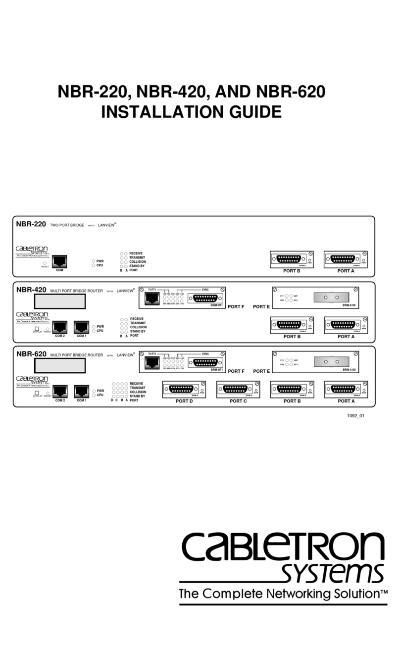
Cabletron Systems
Cabletron Systems NBR-220 installation guide
Panasonic
Panasonic WJ-PB85M16 instructions
Casa Systems
Casa Systems NetComm CloudMesh NF18MESH Settings guide

Dahua Technology
Dahua Technology DH-ITARD-024SA-ST user manual
Eminent
Eminent EM6304 manual
Cisco
Cisco CX-TRIP2 Installation and configuration guide

