Eight CENTURY CC1 User manual
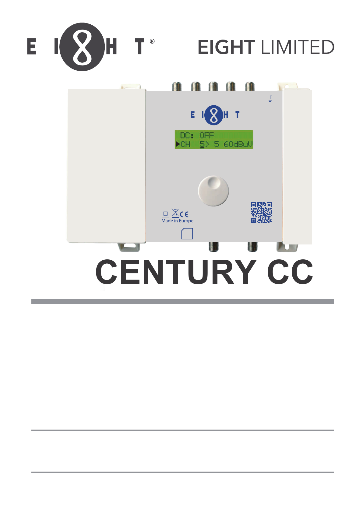
CENTURY CC1
Programmable Channel Converter
產品說明書
User Manual
使用前仔細閱讀本說明書
PLEASE READ THE MANUAL COMPLETELY BEFORE USE
V.20.06
▼ ▼
▼
▼
▼
▼
▼
▼
▼
FM V/U1 V/U2 V/U3 V/U4
CENTURY CC1
Programmable Channel Converter
▼
12-24 VDC
100-240V~
50-60Hz / 15W
▼
OUT
(MAX 118dBµV)
TEST
(-30dB)
SD
User Manual

CONTENTS
1. INTRODUCTION.................................................................................................................... 3
1.1. Product description ..........................................................................................................................................................3
1.2. Typical installation ............................................................................................................................................................3
1.3. Package contents ..............................................................................................................................................................3
1.4. Hardware installation.......................................................................................................................................................4
1.5. Mounting the Pro ler Revolution ...............................................................................................................................4
1.6. Con guring the Pro ler Revolution ...........................................................................................................................5
2. TECHNICAL SPECIFICATIONS ................................................................................................ 11
3. BLOCK DIAGRAM................................................................................................................ 12
4. SAFETY INSTRUCTIONS ....................................................................................................... 13
5. CONDITIONS OF WARRANTY ................................................................................................ 14
P.2

1. INTRODUCTION
1.1.
The Johansson Pro ler Revolution is an easy to use programmable lter ampli er and convertor for terrestrial signals.
The module optimizes terrestrial VHF/UHF and FM signals from multiple inputs with the goal to provide high quality
images on your TV screen. The state-of-the-art programmable lter ampli er has no equivalent on the market due to
its revolutionary technology:
Product description
•Can process more than 50 channels (32 lters)
•Can convert a wide selection of channels
•Sharpest lters on the market (>50 dB on adjacent channels)
•Real-time AGC on all individual lters
•Complete exibility in assigning lters from any input. Each channel can be frequency shifted to any other
channel in the VHF or UHF band (Flex Matrix)
•To avoid unauthorized persons changing the settings, all Pro ler products can be locked with a security
code
•Made in Europe, for worldwide application
•5 inputs: FM / 4 x VHF-UHF / > 50 channels / AGC / 12-24 V remote power
•Product dimensions (H X W X D): 165mm x 217mm x 59mm
1.2.
The Pro ler Revolution can be used to provide high quality television images and FM signals in a wide
range of projects, both in the hospitality as in the residential market. Typical buildings or infrastructures
where the Pro ler Revolution can be used include, but are not limited to:
Typical installation
•Large and small hotels, hostels, bed and breakfasts, holiday parks
•Hospitals, rest homes, prisons, settlements
•Large and small multi-dwelling units
1.3.
•1 Pro ler Revolution (ref. 6700)
Package contents
•1 Power Adapter Cord (180cm)
P. 3

1.4.
Hardware installation
FIGURE 1: TOP VIEW OF PRODUCT
1.5.
•Important: Mount the module vertically to a wall in a well-
ventilated room and leave a minimum space of 15 cm around
the product to guarantee a maximum ventilation of the product
Mounting the Pro ler Revolution
•Connect an earth wire to the grounding clamp
•Connect the power adapter cord to the power supply socket.
Check the status LED for the indication of DC power presence
•Connect the VHF/UHF and/or FM inputs to the Pro ler
Revolution
•Connect a coaxial cable to the output connector for distribution of the signal
•Connect a network analyser to the test port to control the signal quality
•Con gure the Pro ler Revolution using the rotary button, see below
•Optionally: insert an SD card in the SD card slot to upload the con gurations of a previous module or to copy
the con guration to another module
•The power adapter can easily be replaced without disconnecting the product. To do so, open the top left
plastic cover by pushing the click at the opposite side of the mains connector
▼ ▼
▼
▼
▼
▼
▼
▼
▼
FM V/U1 V/U2 V/U3 V/U4
CENTURY CC1
Programmable Channel Converter
▼
12-24 VDC
100-240V~
50-60Hz / 15W
▼
OUT
(MAX 118dBµV)
TEST
(-30dB)
SD
User Manual
5 input: 4 VHF/UHF and 1 FM
Grounding clamp
Use the knob to navigate through
the menu
Test portto control the output signal quality
Output signal
Status LED
Power supply socket
16.5cm
21.7cm
P.4

1.6.
NAVIGATING THROUGH THE MENU
Conguring the Proler Revolution
Use the Johansson rotary/push button to navigate through the menu. This is very straightforward and simple. The
table below shows how the rotary/push should be used:
Push the button 2s to enter the basic
conguration.
Push the button to conrm your selections.
When rotatingthe button, you scroll
through the dierent screens.
MENU OVERVIEW
INPUT FM INPUT V/U 1 - 4 OUTPUT ADVANCED LOAD SD PRESET SAVE SD PRESET EXIT
GAIN PRE-AMPLIFIER LEVEL LANGUAGE PRESET X CREATE PRESET LOCK
DC SLOPE REGION
DELETE ALL NO LOCK
ADD CHANNEL VHF ATTN DC VOLTAGE
BANDWIDTH
FW VERSION
SERIAL NUMBER
FORMAT CARD
REGION/COUNTRY SETTINGS
IMPORTANT! Before starting the conguration, it is advised to set the correct
region or country. Unpower the unit, push the button and keep pushing the
button while you repower the unit. Release the button when the display shows “RESET FINISHED”.
Now the product is reset and will ask you to enter country or region. This will amongst others determine the channel
plan for VHF and UHF and the DC voltage for the inputs(12 or24V).
P. 5
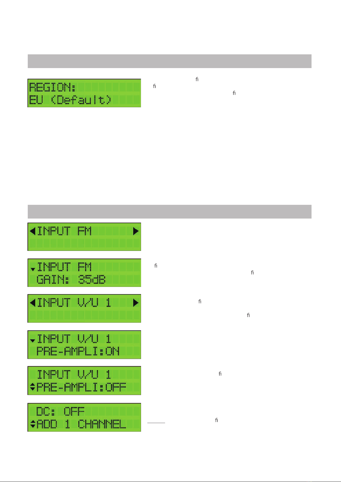
To activate the correct channel frequency plan, select the country or
region where the Pro ler Revolution is situated. Rotate to select and
con rm by tapping the rotary button.
The default setting is Europe. The Pro ler Revolution is also
operational in the following countries/regions: Australia, Brazil,
China, Hongkong, Italia, New-Zealand, Russia, South Africa, UK and
USA.
All the following menu items can be accessed without the reset procedure.
Push the rotary button for 2 seconds to access the menu
INPUT SETTINGS
DISPLAY READOUT EXPLANATION
Tap the rotary button to enter the INPUT FM menu. Rotate the
button to navigate through the submenu.
To lter and amplify an FM signal, tap GAIN, select the gain of the
input FM signal (15 to 35 dB) and tap to con rm.
Remark: DAB should be added via V/U input 1-4.
After INPUT FM is con gured, scroll up to the top of the menu
(INPUT FM), tap the rotary button and scroll right to INPUT V/U 1.
Tap INPUT V/U 1 to enter the menu to con gure input 1.
Rotate the rotary button to scroll down in the submenu of INPUT
V/U 1.
PRE-AMPLI: The internal ampli er is by default ON, only in case of
very strong incoming signals (if the strongest channel on that input
is higher than 80dBµV), it can be advised to switch this OFF.
DC: Decide whether the input should provide power to an external
amplifier. Choose between OFF or 12 V.
Remark: If the external ampli er needs 24 V, you can change this in
advanced settings (see further).
P.6
DISPLAY READOUT EXPLANATION

DISPLAY READOUT EXPLANATION
Tap Add Channel to add channel.
Up to 6 channels can be added at once.
First select the starting channel (e.g. CH5) and tap to conrm.
Then select the stop channel (e.g. CH7, this means that you will
add 3 channels). Tap to conrm. Then you can convert them using
the rotary button (e.g. CH5 to CH7 converts to CH8 to CH10) and
tap to conrm.
Some other examples:
To add CH5 and convert to CH6,
select as follows: 5: 5 6: 6
To add CH21-22-23 and convert to CH31-32-33, select as follows:
21:23 31:33
Remark 1: The value 85dBµV (in the bottom right corner) indicates
the incoming level of the channel.
Remark 2:For EU, Italy and New-Zealand region, Channel 13 (230-
240MHz) can be used. CH13 cannot be converted.
For optimal performance we recommend to only add single channels, unless you need to process
a lot of channels.
DISPLAY READOUT EXPLANATION
To add another (group of) channel(s), scroll down to ADD CHANNEL
and tap to conrm.
To prevent bad quality or scrambled images, make sure that only
one input channel is assigned to one output channel. If 2 channels
are assigned to the same output channel, a star () will appear.
The same applies for adding multiple channels. Make sure that each
output channel is selected only once.
After this, the correct LTE lter will be set for the UHF inputs (possible lters are 694MHz, 790MHz or OFF). If the
channels are lower than 48,the 694MHz lter is activated. The 790MHz lter is activated for the channels lower than
60.
To delete a (pair of) channel(s), position the arrow on the channel and press
the rotary button 3 seconds.
P. 7
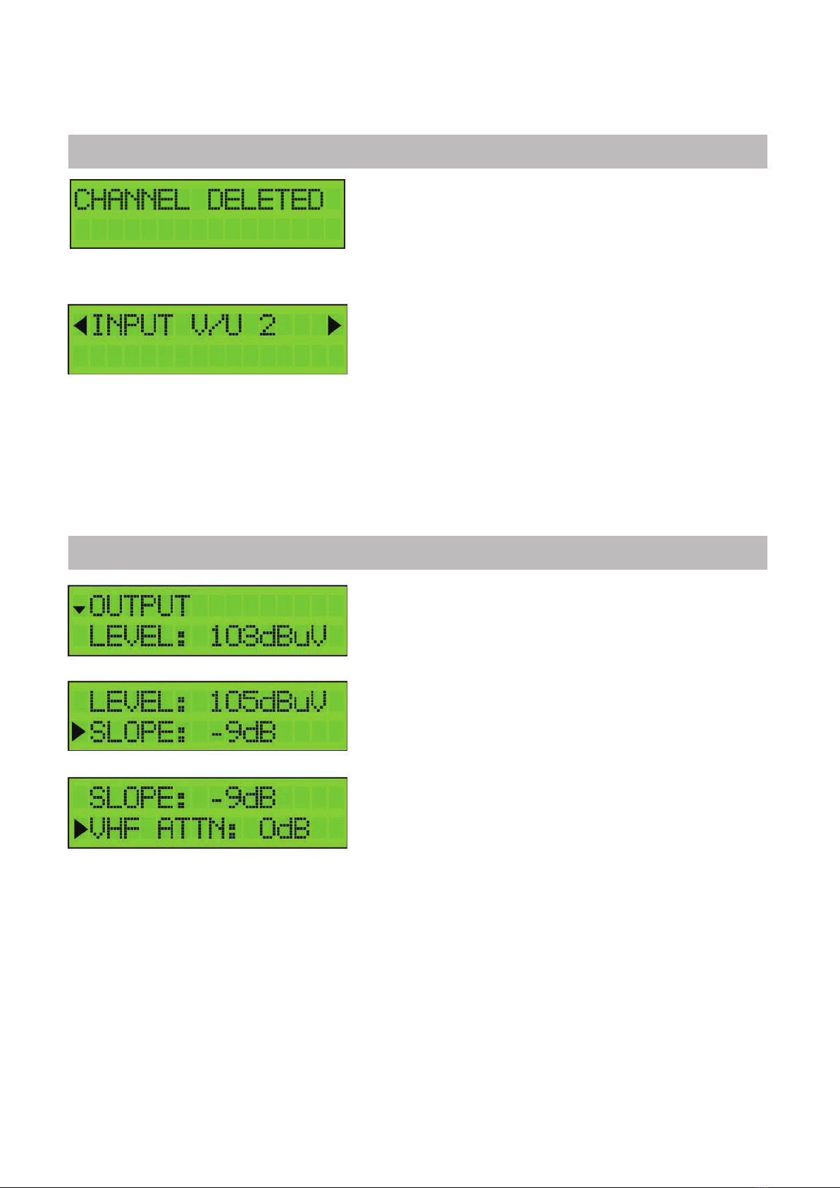
DISPLAY READOUT EXPLANATION
To delete a (pair of) channel(s), position the arrow on the channel
and press the rotary button 3 seconds.
When you have added all the channels to INPUT V/U 1, and you
want to add channels to the other inputs, scroll up to the top of the
menu (to INPUT V/U 1), tap the button and scroll to the next input.
Repeat the previous steps for all input channels.
OUTPUT SETTINGS
DISPLAY READOUT EXPLANATION
Dene the OUTPUT LEVEL of the output signal.
Range between 98 dBµV and 118 dBµV (default output level is 108
dBµV). Check the output via a network analyser on the -30dB test
port.
Note: The more channels you select, the less input power you
should give (e.g. 111 dBµV for 10 channels).
A SLOPE of up to -15dB can be set between the beginning of BIII
and the end of UHF to compensate for cable losses. 0dB means all
channels have the same output level (see previous display readout),
-15dB means the beginning of BIII (174MHz) is 15dB weaker than
the end of UHF.
VHF ATTN: To compensate for cable losses, an attenuator of up to
15 dB can be congured to decrease the VHF and DAB output level
(compared to the UHF output level).
Note: In the OUTPUT menu, you dene the output level in dBµV of the MUX’s. The Proler Revolution has enough
gain to guarantee this output level under all input conditions. In case a slope has been set, the output level indicated
on the display will be the output level of the highest frequency MUX.
P. 8
ADVANCED SETTINGS
DISPLAY READOUT EXPLANATION
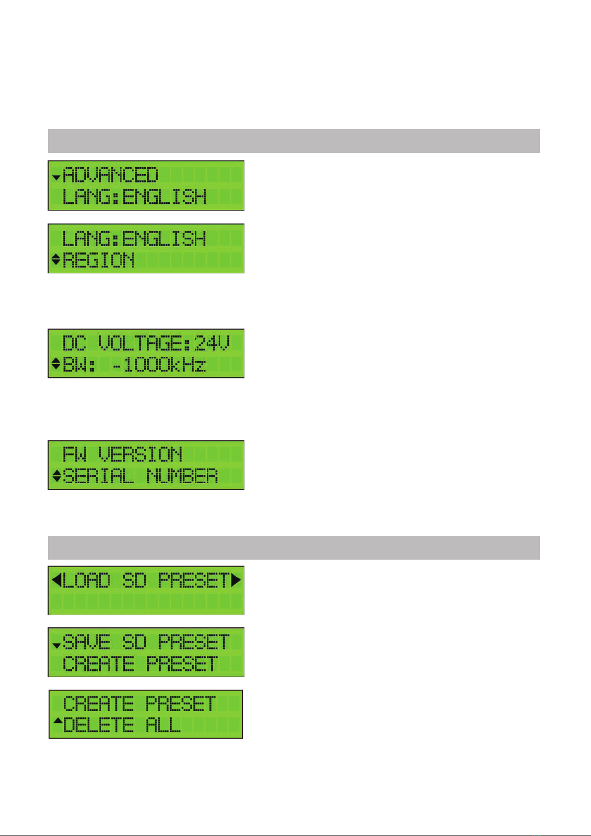
The language of the Proler Revolution can be set to English,
Italian, Spanish or French.
Tap REGION to check to which region/country the Proler
Revolution is set. To change the region/country, a hard reset is
required (see instructions above (cfr. REGION/COUNTRY SETTINGS).
Dene DC VOLTAGE for the inputs, choose between12V or 24V.
This is a global setting for all inputs, each input can then be
switched between OFF or this value.
(cfr. STEP 2). All countries are set by default on24V, except UK
which is set by default on12V.
Tap FW VERSION to check the rmware version of the device.Tap
SERIALNUMBER to check the serial number of the device. To format
the SD CARD, tap FORMAT CARD.
SD CARD SETTINGS
DISPLAY READOUT EXPLANATION
To upload settings from a SD card, tap LOAD SD PRESET. This will
copy the conguration le from the SD CARD to the device.
To save the device settings on the SD CARD, go to SAVE SD PRESET
and tap on CREATE PRESET.
It is possible to create multiple presets. Therefore, tap CREATE
PRESET after each modication of the settings.
To delete all presets, press DELETE ALL.
P. 9
The lter bandwidth can be changed from -2000 kHz to 0 kHZ in
steps of250 kHz.
This allows you to optimize the bandwidth of your lter.
For instance, a European 8 MHz channel can be changed from 6 to
8 MHz. The default setting is -1000 kHz, which is an optimal setting
in 95%of the cases.
EXIT SETTINGS
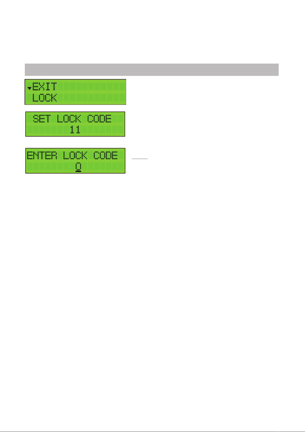
DISPLAY READOUT EXPLANATION
To avoid unauthorized people changing the settings, all Proler
products can be locked with a security code.
Select LOCK and SET LOCK CODE.
When the lock code is set, the device will shut down.
When you restart the device, you will now have to enter the correct
lock code.
Remark: If you forgot the lock code, you can always use the value
50. This master code is xed and cannot be changed.
If you do not want to work with a lock code, go to EXIT and tap NO
LOCK.
P.10
2. TECHNICAL SPECIFICATIONS
Programmable Channel Converter-CENTURY CC1
Inputs - 4 VHF/UHF + 1FM
Outputs - 1 main (FM-VHF-UHF) + 1 test port (-30dB)
Frequency range MHz
MHz
MHz
FM: 88 - 108
VHF:174 - 240
UHF: 470 - 862
LTE protection MHz Automatic selection: 694, 790 or OFF
Input level dBµV
dBµV
dBµV
FM: 37 - 77
VHF: 40* - 109
UHF: 40* - 109
FM Output power (60dB/IM3)
VHF/UHF Output power (60dB/IM3)
VHF/UHF Output power (35dB/IM3)
VHF/UHF Output power with 1 MUX
VHF/UHF Output power with 6 MUX
dBµV
dBµV
dBµV
dBµV
dBµV
113
120
131
118
114
Conversion
-
Yes (from any VHF-UHF channel to any VHF-UHF channel)
Add channels - Per 1, 2, 3, 4, 5 or 6 MUXes
Number of channels - More than 50 (32 lters)
Gain dB
dB
dB
FM: 35
VHF: > 75
UHF: > 75
Gain adjustment : FM
VHF/UHF
dB
-
20
Channel AGC
General attenuator dB 20
VHF/DAB attenuator dB 15
Slope adjustment dB 15
Selectivity
dB/1MHz
50
Output MER dB
dB
VHF: 35
UHF: 35
ESD protection - All inputs
Remote voltage for
preamp
Remote current
V
mA
12 or 24
100 (total for the 4 inputs)
SD port - Yes (for copy con guration)
Operating temperature °C -5 to +50
Power Supply Vac 100 - 240
Power consumption W 15
Dimensions mm 217 x 165 x 59
Weight kg 0,8
* For 64QAM with code rate 3/4
P.11

P.12

4. SAFETY INSTRUCTIONS
Read these instructions carefully before connecting the unit
Topreventre,shortcircuitorshockhazard:
•Do not expose the unit to rain or moisture.
•Install the unit in a dry location without inltration or condensation of water.
•Do not expose it to dripping or splashing.
•Do not place objects lled with liquids, such as vases, on the apparatus.
•If any liquid should accidentally fall into the cabinet, disconnect the power plug.
Toavoidanyriskofoverheating:
•Install the unit in a well aired location and keep a minimum distance of 15 cm around the apparatus for sucient
ventilation
•Do not place any items such as newspapers, tablecloths, curtains,
on the unit that might cover the ventilation holes.
•
Do not place any naked ame sources, such as lighted candles, on the apparatus
•
Do not install the product in a dusty place
•
Use the apparatus only in moderate climates (not in tropical climates)
•
Respect the minimum and maximum temperature specications
To avoid any risk of electrical
shocks:
•Connect apparatus only to socket with protective earth connection.
•The mains plug shall remain readily operable
•Pull out power plug to make the dierent connections of cables
•To avoid electrical shock, do not open the housing of adapter.
Maintenance
Only use a dry soft cloth to clean the
cabinet.
Do not use solvent
For repairing and servicing refer to qualied
personnel.
Dispose according your local authority’s recycling processes
P.13

Table of contents
Other Eight Media Converter manuals


Popular Media Converter manuals by other brands

American Dynamics
American Dynamics VideoEdge Installation and user guide

Alpha Technologies
Alpha Technologies CXDF 24-48/2kW Installation & operation manual

Ikegami
Ikegami IEN-T01P instruction manual

Core Tec Communications, LLC
Core Tec Communications, LLC VCX-7401 Installation and operating instructions

GMI
GMI D1053S instruction manual

Icy Box
Icy Box IB-SPL1029AC manual


 user guide")
