Core Tec Communications, LLC VCX-7401 User manual

1
INSTALLATION AND OPERATING INSTRUCTIONS
Revision Date: June 8, 2012
VCX-7401 Dual H.264/MPEG-4/MPEG-2/JPEG Encoder with
H.264/MPEG-4 Decoder
Core Tec Communications, LLC
2950 Lake Emma Rd
Suite 1030
Lake Mary, FL 32746 USA
Phone (407) 331-0547
Fax (407) 331 0656
www.coretec.com
Technical Support:
U.S. 877-331-0547
(Toll Free)
Elsewhere: 407-331-0547

2
Table of Contents
Table of Contents................................................................................................................ 2
Introduction......................................................................................................................... 4
Familiarization with the VCX-7401 ................................................................................... 5
Com Port Data Interface ................................................................................................. 6
Video Input Interface ...................................................................................................... 6
Ethernet Interface............................................................................................................ 6
Power .............................................................................................................................. 7
Mounting the Device....................................................................................................... 7
Updating Firmware with TFTP....................................................................................... 7
Operation............................................................................................................................. 7
Limitations...................................................................................................................... 7
Decoding on 3rd Party Decoders ..................................................................................... 8
Using RTSP..................................................................................................................... 8
IP Configuration.................................................................................................................. 8
Overview......................................................................................................................... 8
Initial IPAddressing........................................................................................................ 8
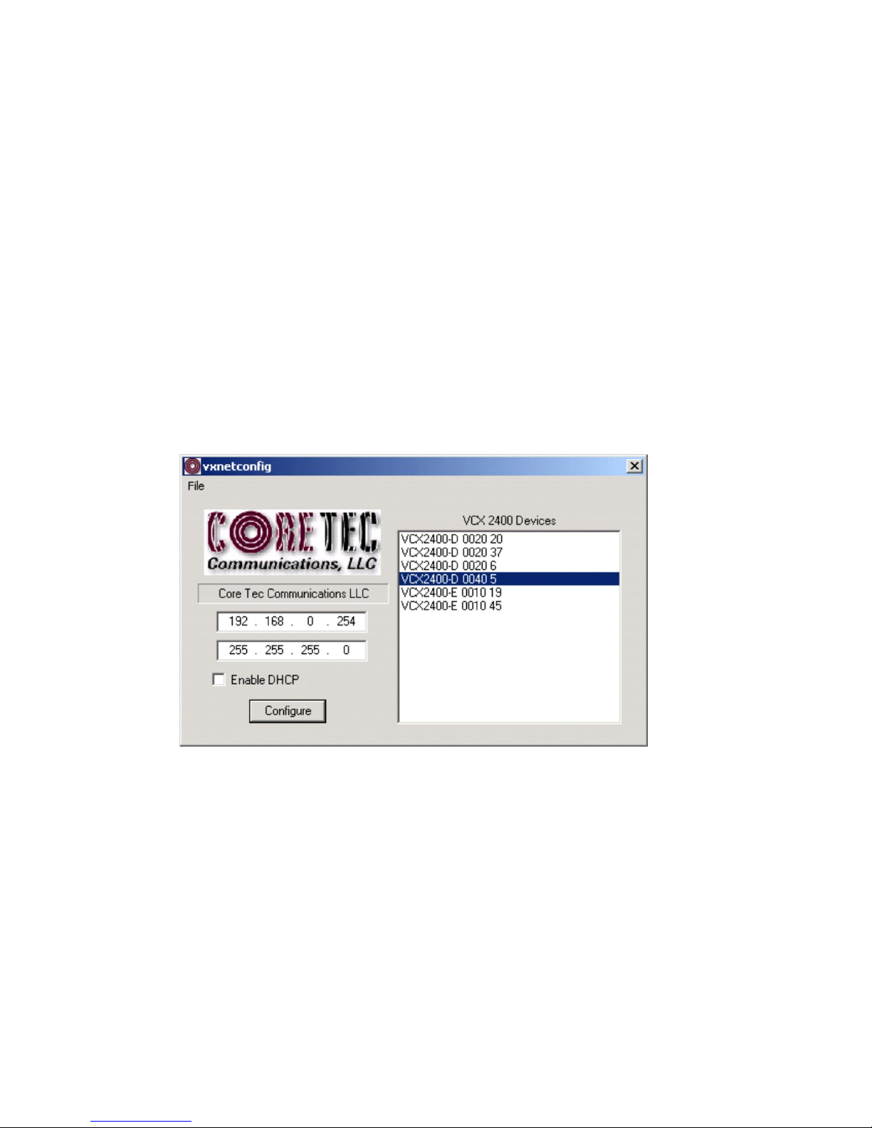
VcxNetConfig............................................................................................................. 9
Connecting to the Unit...................................................................................................11
1. Telnet ...............................................................................................................11
2. Terminal Program............................................................................................11
3. Web Interface.................................................................................................. 12
4. SNMP ............................................................................................................. 25
Program Commands.......................................................................................................... 25
Command Legend:........................................................................................................ 26
Network Settings........................................................................................................... 26
COM Port Settings........................................................................................................ 28
OSD COMMANDS (On Screen Display).................................................................... 29
Video Settings & Commands........................................................................................ 30
SAP Settings ................................................................................................................. 31
SNMP Settings.............................................................................................................. 32
Miscellaneous Settings & Commands .......................................................................... 33
Specifications.................................................................................................................... 34
PHYSICALAND ENVIRONMENTAL ...................................................................... 34

3
POWER REQUIREMENTS......................................................................................... 34
CONNECTORS............................................................................................................ 34
ELECTRICAL.............................................................................................................. 35
Models............................................................................................................................... 36
BASE MODELS........................................................................................................... 37
Appendex A - Pinouts ....................................................................................................... 37
Appendex B –VideoLan Client........................................................................................ 39

4
Introduction
The model VCX-7401 is the stand-alone H.264/MPEG4/MPEG-2/JPEG version
of the VCX family and is housed in a 8.5-inch 1U rack mount case with a control
port and a universal AC power supply.
The VCX Digital Video transport system consists of two video encoders, allowing
either H.264, MPEG4, MPEG2 or JPEG as well as a built in decoder. This makes
up the encoder(selectable)/decoder pair providing the capability for one-way end-
end transmission of the compressed digital video stream in the H.264 or MPEG-4
format. The encoding-decoding process is applied to an NTSC (or PAL) video
input, selected in software.
Modification of video format and resolution, data sub-channel characteristics, and
basic IP parameters is achieved through one of the following means:
a) Terminal Program
b) Telnet through the Ethernet connection
c) Web Interface Applet
d) SNMP
NOTE: The VCX7401 is optimized for encoder or decoder operation. While
both the encoders and decoder can be used simultaneously, it is not recommended
as perfomance issues may occur. The exception is using the decoder to view it's
own H.264 or MPEG-4 stream, as this has minimal affect on performance.

5
Familiarization with the VCX-7401
The VCX-7401 Video Encoder accepts one BNC video in, one BNC Video Out
and one data sub-channel. The encoder has a programmable reset, which prompts
the re-initiation of the video stream. The decoder also has a programmable reset
command, tied to errors in the incoming video stream, as well as a reboot
command.
Birds Eye view of the VCX-7401
Front Panel
Front view of the VCX-7401

6
Back Panel
Rear view of the VCX-7401
Com Port Data Interface
There is one bi-directional data interface, RS-232 and RS-422 selectable, on the encoder,
which uses a RJ-45 connector. Refer to Table below, in Appendix A, for the correct pin
out. When using the RS-232 configuration pin 4 is ground. Com Port parameters are
configured through the system software.
Refer to AppendixAfor the correct pin out.
Video Input Interface
Connect a BNC-terminated coaxial cable from a composite video source (e.g., CCTV
camera) to the BNC connector labeled “VIDEO IN” (encoder). The composite video
input should be in NTSC or PAL format. The maximum length of cable that should be
interfaced to the encoder or decoder is 100 feet, although the specific installation
environment will dictate the actual permissible length.
Ethernet Interface

7
There is one Ethernet interface for encoder or decoder, which uses a standard RJ-45
connector. The standard method of terminating an ETHERNET cable reflects the
TIA568Astandard (Telecommunications IndustryAssociation standard).
Refer toAppendixA for the Straight Through and Crossover Ethernet Pin Out.
Power
Power is applied through a standard IEC type detachable line cord at the rear of the unit.
The unit automatically senses 110 VAC or 220 VAC supply and will operate with either.
The typical current is 1.2 amps from a 110VAC line and drops to 0.9 amps from a 230
VAC line source.
Mounting the Device
The VCX-7401 Encoder is a 8.5 inch wide device and provides holes for
mounting onto a chassi. The unit can be mounted in any orientation.
Updating Firmware with TFTP
TFTP is a simple and reliable way of updating the firmware on any device. All that is
required is to have access to a TFTP server which will be used as the host and contain the
update file, which is named vcx7401.tgz.
Via Telnet, enter the following command in order to update the firmware for the device
that is being used.
TFTP <Server IP Address>
Operation
The VCX-7401 is capable of encoding up to 2 simultaneous streams of video, or decode a
single video stream. When encoding, the video streams can be set to a multicast or
unicast IP.
Limitations
There are limitations imposed on the user when configuring the VCX-7401. They are as
follows.
Only the encoder or the decoder can be configured for operation at the same time.
When using both encoders H264 and MPEG4 cannot be used together at this time.

8
The CPU load should be observed (Telnet or Web) when configuring the bitrates.
The MPEG-2 stream is elementary.
Both the H.264 and MPEG-4 streams are RTP.
The JPEG images are uploaded using FTP to server.
Decoding on 3rd Party Decoders
There are several methods that allow decoding on non- Coretec decoders.
SAP –H.264, MPEG-4, and MPEG-2 are supported.
RTSP/RTP –H.264 and MPEG-4 are supported
UDP –MPEG-2 is supported.
The freely available no-cost media player called VideoLan Client or VLC is compatible
with the VCX-7401. It is available from www.videolan.org.
Using RTSP
RTSP (Real Time Streaming Protocol) is the protocol that many decoders use to access
the encoded stream. RTSP establishes a TCP connection with the VCX-7401 and
requests the data necessary to determine the type of stream and the connection IP/Port.
The information to create the RTSP request is provided by the user in the form of a URL.
The following is an example URL based on an example IP address used for the VCX-
7401.
rtsp://192.168.0.253/stream1 –Accesses the stream from the 1st encoder.
rtsp://192.168.0.253/stream1 –Accesses the stream from the 2nd encoder.
rtsp://192.168.0.253 –Accesses the stream from the 1st encoder.
RTSP only works with the encoder set to H.264 or MPEG-4.
IP Configuration
Overview
The commands contained in this section provide the means to configure critical
network, com ports, encoder, and decoder parameters. The user should consult
the factory if specific functions of interest do not appear to be supported.
Initial IPAddressing
To set the device parameters properly, encoder and decoder units must be given
appropriate IP addresses, compatible with the network on which they are to be
connected. There are two methods for setting the network address.

9
Set your computer’s IP address to the subnet of the default IP of the VCX-
7400. The default IP and subnet are 192.168.0.253 and 255.255.240.0.
You can set your computer to any other address on the subnet. After
putting your computer on the subnet, use telnet to set VCX-7401 network
parameters as decided by you or your network administrator.
a. IP
b. Subnet mask
c. Optional the gateway.
The software module VXNETCONFIG was developed to allow a
network administrator to set the IP and Subnet in the VCX-7401 without
having to modify the computer’s network address.
VcxNetConfig
Contact Core Tec to download VcxNetConfig. Select VcxNetConfig by double
clicking on the program. The following window will open:
VCXNETCONFIG Window

10
Description of Program Functions
(a) The first box on the left hand side of the window displays the current IP
address of the CORE TEC device being interrogated. Type the new IP address
into this space
(b) The second box is used to change the SUBNET address. Note that the
address displayed is always 255.255.255.0. Type the new SUBNET address into
this space.
(c) The Enable DHCP box is checked when DHCP is to be enabled.
NOTE: DHCPis not currently enabled on the VCX-7401. Selecting DHCP
will have no affect.
(d) The Configure button is to execute the requested changes to the IP and
SUBNET information. Note that future queries of the SUBNET will indicate
255.255.255.0. Therefore, the correct SUBNET address should always be entered
prior to using the Configure button.
(e) The box on the right hand of the window displays all VCX-7401 devices
(encoders and decoders) on the network.
(f) To make a change to the equipment addressing perform the following
steps:
(g) Select the Core Tec device address from the list in the box on the right side
of the window.
(h) Move the cursor to the IP box and select the first octet by highlighting the
octet. Enter the new IP data for the selected octet. As the 3 digits are entered, the
software will automatically highlight the next octet for change. Complete
entering the IP address and then switch to the SUBNET data.
(i) Move the cursor to the SUBNET box and select the first octet by
highlighting the octet. Enter the new SUBNET data for the selected octet. As the
3 digits are entered, the software will automatically highlight the next octet for
change. Complete entering the SUBNET data.
(j) To execute the change press the configure button. The IP address and the
SUBNET will be updated in the selected Core Tec equipment. The new IP
address will be displayed. The SUBNET will display a default class C- SUBNET
there is no read back of the changed SUBNET displayed.
(k) Repeat this process for all the CORE TEC equipment requiring change.

11
Connecting to the Unit
There are currently three ways to connect to the VCX-7401.
1. Telnet
Password: admin (default)
To change the default password perform the following:
Type: PASSWORD <followed by your password (up to 11 characters)>
Where <your password> equals the new password.
For configuration using an Ethernet connection, activate the Telnet function by
the following:
Initiating from the Command Prompt - Telnet nnn.nnn.nnn.nnn
Use the MS Windows –START –RUN Telnet nnn.nnn.nnn.nnn
(where nnn.nnn.nnn.nnn is the IP address of the unit being configured)
Employ the command set as described below.
Note that the initial IP addresses (factory default) are:
Encoder 192.168.0.253
Decoder 192.168.0.254
Subnet Mask 255.255.255.0
2. Terminal Program
NOTE: The following procedure is valid for standalone units only and is not
applicable to rack mount units.
The Terminal Program, such as HyperTerminal, configuration procedure uses the
serial connection on the front of the unit.
Using the PCA-2400 programming cable, connect to the control port. This cable
should be attached to the serial port of an attached PC and the Hyper Terminal
program launched. The PC should have its Com Port configured as:
Baud rate 115,200 kbps
Data bits 8 bits
Parity No Parity

12
Stop Bits 1 Stop Bit
Flow control None
Activate the HyperTerminal function, normally found in a sub-menu under
ACCESSORIES. Employ the command set as described in the following section.
Password: admin (default)
To change the default password perform the following:
Type: PASSWORD <followed by your password (up to 11 characters)>
Where <your password> equals the new password
3. Web Interface
The web interface works with Internet Explorer, Mozilla Foxfire, and Google Chrome.
The web interface is capable of viewing the streaming video in the H264, MPEG-4, and
MPEG-2 formats. However this functionality requires the installation of VLC and either
the Firefox or Chrome browser. Please refer to the appendex section on VideoLan Client
before installing VLC.
To get to the Login Page of the web interface, the user needs to type in the IP address of
the device into the address bar. On the Login Page, shown below, the user will need to
type in the password to login successfully.

13
Login Page of Web Interface Applet
When the unit accepts the log in (default password: admin), the following web
page will be displayed.

14
On the top of the screen is a front view image of the device. If you click on any of
these ports the associated tab will appear below the image inside the tabbed pane.
Also an animation will appear for a few seconds on the bottom right corner. The user
may click here in order to to be sent to tutorial page. The user will find here, all the
associated documents to the VCX-7401, such as the manual and video tutorials on
how to use the device and the web applet. Aside from clicking on the ports in the
image of the device at the top of the applet, they can click directly on the tabs below.
There are currently ten tabs to choose from: Main, Network, Subchannel, OSD, Video,
Encoder1, Encoder2, Decoder SNMP, and Miscellaneous. To the right the user will
see 7 buttons: Logout, Commit, Commit/Reboot, Reboot, Open Manual and two other
buttons that allow you to view either the Encoder1 or Encoder2 video stream on a
new web page.

15
Main Tab

16
Network Tab

17
Subchannel Tab

18
OSD Tab

19
Video Tab

20
Encoder1 Tab
Table of contents
Other Core Tec Communications, LLC Media Converter manuals