Ikegami IEN-T01P User manual

Ikegami Tsushinki Co., Ltd.
INSTRUCTION MANUAL
(SETUP INSTRUCTIONS)
MODEL
OUTDOOR USE WARNING
WARNING — TO PREVENT FIRE OR
ELECTRIC SHOCK, DO NOT
EXPOSE THIS APPLIANCE TO RAIN
OR MOISTURE.
IEN-T01P
NETWORK ENCODER
e
c
o
p
r
o
d
u
c
t
s

Instructions for Disposal of Electric and Electronic Equipment in Private Household
Disposal of used Electric and Electronic Equipment
(Applicable in the European Union and other European countries with separate
collection systems)
This symbol on the product, or in the related documents in the package, indicates that this product
shall not be treated as normal household waste. Instead, it should be taken to a proper applicable
collection point or depot for the recycling of electric and electronic equipment.
By ensuring this product is disposed of correctly, you will help prevent possible negative consequences for the
environment and human health, which could otherwise be caused by inappropriate waste handling of this
product. The recycling of materials will help to conserve natural resources.
For more detailed information about recycling of this product, please contact your local city authority, your
household waste disposal service or the place where you purchased the product.

Introduction
Thank you very much for your wise choice of this product. Be sure to carefully read this manual
before use in order to fully understand the product’s functions and to keep the product at full
capacity.
Handling precautions
Be very careful to keep the product from impacts and vibrations. Otherwise it
may get in trouble.
1. Installation location and conditions
* Be sure to keep off the power while installing the product.
* Never open the housing. Otherwise the internal precision parts may get damaged, resulting in
failure or accident.
* Install the product in a place within its ambient temperature range and without condensation.
* Do not block nor cover the product’s vent.
* Make sure the supply voltage is as specified.
* Handle the product with care. Impacts and vibrations may get it scratched or in trouble.
* Do not install the product in a hot spot: not exposed to direct sunlight nor near a heating
element, for example.
* Do not install the product in a strong magnetic field or exposed to radio waves.
* Do not place this product near a radio, TV set and other signal receiver. Such equipment may
suffer from poor signal reception.
* Do not move the product with the power on.
2. Copyrights and the protection of personal information
* Take proper measures for delivering copyrighted and personal video materials.
Checking the supplies
Quantity
* Instruction Manual .................................................................... 1

Contents
Page
Introduction
Handling precautions
Checking the supplies
Contents
1. Outline ............................................................................................................. E-1
2. Features ........................................................................................................... E-1
3. Names of parts and their functions .................................................................. E-2
3-1. Front panel ................................................................................................ E-2
3-2. Rear panel ................................................................................................ E-2
4. Basic connections Connecting the LAN cable ............................................................................... E-3
4-1. Direct connection with a PC ...................................................................... E-3
4-2. Connection with Ethernet (hub) ................................................................ E-3
5. Applied connections Connecting to the alarm terminals or RS-485 terminals .............................. E-4
5-1. Connecting to the alarm terminals ............................................................ E-4
5-2.Connecting to the RS-485 terminals .......................................................... E-4
6. Applied connections Connecting to the RS-232C connector and AUDIO terminals ..................... E-5
6-1. Connecting to the RS-232C connector ..................................................... E-5
6-2. Connecting to the AUDIO terminals .......................................................... E-5
7. Setting up a PC Setting the IP address and Internet Explorer ........................................................ E-6
7-1. Setting the IP address .............................................................................. E-6
7-2. Setting Internet Explorer ........................................................................... E-9
8. Turning on the power ....................................................................................... E-10
9. Hooking up the PC to the encoder ................................................................... E-10
10. Setting the encoder Making the IP address and other settings ..................................................... E-11
11. Troubleshooting ............................................................................................... E-12
12. Specifications ................................................................................................... E-13
13. Appearance view ............................................................................................. E-14
14. Warranty and after-sales service ..................................................................... E-15

E-1
1. Outline
This box-type network encoder is compatible with PoE (Power over Ethernet) backed by the web
server function. The video and audio signals of conventional analog surveillance cameras can
be processed and sent across a network. The built-in JPEG2000 image compression format can
deliver high-quality video in a scalable way. Hooked up with your existing surveillance cameras,
your system can be easily networked.
Thanks to the outdoor-use motion detector that does not mistakenly react to tree leaves trem-
bling in the wind, the alarm function minimizes false alarms. What’s more, areas that should not
be watched yet appear onscreen can be masked by the privacy masking function.
2. Features
(1) High-quality picture
The wavelet transformation JPEG2000 image compression format provides for high com-
pression ratio and quality images. A three-dimensional comb filter is adopted for video inputs
to achieve better picture quality.
(2) Scalable streaming
The scalable function, one of the JPEG2000 features, enables to select an image’s resolu-
tion and to watch the image through a general-purpose browser at each network terminal. Up
to 25 frames/second can be advanced onscreen in a smooth motion, and high-precision
images can also be captured for data saving. In this way, the surveillance level may be
scaled according to the terminal performance.
(3) Outdoor-use motion detection
The outdoor-use motion detector is designed not to erroneously detect tree leaves that sway
in the wind. False alarms can thus be minimized.
(4) Alarm function
The pre-alarm function records images that have been shot before an alarm is given. A
notice function enables to send a message to a designated e-mail address.
(5) Maintenance
Via the network, the product software can be updated and self-diagnosed for real-time main-
tenance.
(6) External equipment control
Control data via the network are converted by RS-232C and RS-485 interfaces to control
external equipment.
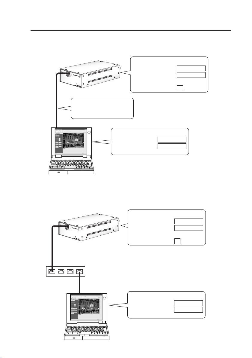
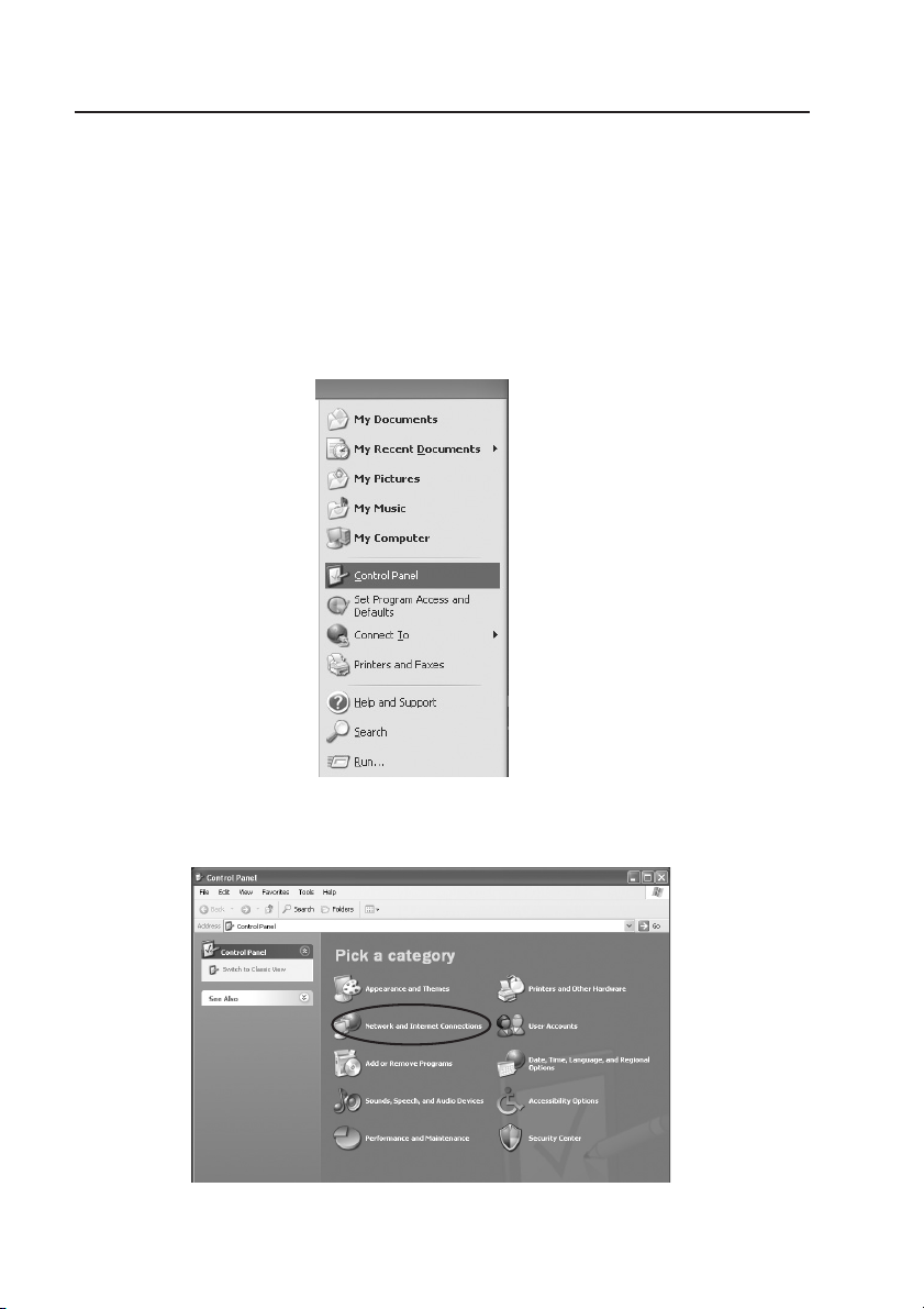
(7) PoE (Power over Ethernet)-compatible
The PoE-compatible hub is intended to supply power through the Ethernet cable.

E-2
3. Names of parts and their functions
3-1. Front panel
① ETHERNET
Used to connect the LAN cable (Category 5 or higher). PoE-compatible.
② LED indicators
Green : Normally flashing
Orange : Flashing while video signals are inputted normally
③ INIT switch
* Hold down the switch, turn on the power and keep it down for more 10 seconds. This will
return the product’s settings to its factory ones. It is helpful if the firmware fails to be up-
loaded, for example. In such case, the IP address and the firmware itself resume their
factory settings. The IP address and other settings must be made again.
3-2. Rear panel
① VIDEO IN
Used to receive video signals from cameras. Equipped with automatic terminating function.
② VIDEO OUT
Used to send out VIDEO IN signals. When a coaxial cable is connected, the termination is
automatically cleared.
③ Terminal block 1
IN : Normally open no-voltage contact alarm input. External sensor or the like con-
nected here.
OUT : Open-collector output. Alarm output given if the motion detector gets activated or if
the IN terminal gets short-circuited.
RS-485 : Ikegami’s I-LAN-compatible device communicable with a PC.
④ Terminal block 2 (Power)
Used to commonly receive DC12V and AC24V power.
*This installation should be made by a qualified service person and should conform to all local codes.
Priority is given to the PoE (Power over Ethernet) power supply.
⑤ RS-232C
RS-232C communication enabled (DCE: Data Communication Equipment)
⑥AUDIO
IN: Used to receive audio signals.
OUT: Used to send out audio signals.
⑦Power
Usually not used.
Priority is given to the PoE (Power over Ethernet) power supply.
① ②
③
Network Encoder
MODEL
IEN
-
T01
ETHERNET
①
⑤ ⑥ ⑦
② ③ ④
DC12V
OUT
AC24V
50/60Hz
DC12V
6.5W
IN
OUT OUT RS485
IN IN
AUDIO
CLASS 2
VIDEO
RS-232C (DCE)

E-3
4. Basic connections Connecting the LAN cable
4-1. Direct connection with a PC
Use a Category 5 or higher LAN cable (cross cable).
4-2. Connection with Ethernet (hub)
Use a Category 5 or higher LAN cable (straight cable).
IEN-T01
PC
IEN:192.168.1.100
PC:192.168.1.10
Example(IEN-T01)
IP IPaddress :192.168.1.100
Subnetmask :255.255.255.0
Username :[admin]
Password :1
Example(PC)
IP IPaddress :192.168.1.10
Subnetmask :255.255.255.0
Fordirectconnection:
UseanLANcable
(crosscable).
IEN-T01
PC
IEN:192.168.1.100
LANcable(straightcable)
PC:192.168.1.10
Example(IEN-T01)
IP IPaddress :192.168.1.100
Subnetmask :255.255.255.0
Username :[admin]
Password :1
Example(PC)
IP IPaddress :192.168.1.10
Subnetmask :255.255.255.0
HUB

E-4
Max DC24V 50mA
Open collector
No-voltage contact
External unit’s alarm input
Alarm
+24V
10KΩ
OUT RS485IN
Twisted pair cable
Presettable controller
PCS-351
Coaxial cable
Presettable
camera
I-LAN-compatible equipment
OUT RS485IN
5. Applied connections Connecting to the alarm terminals or RS-485 terminals
5-1. Connecting to the alarm terminals
Make sure in advance that the encoder power is not turned on.
* Typical connections
* Alarm action
IN : If an alarm signal comes in, the alarm message is e-mailed to a designated ad-
dress. An alarm output is given.
OUT : If the alarm input is short-circuited or the motion detector is activated, an output is
given for a specified time.
5-2. Connecting to the RS-485 terminals
Make sure in advance that the encoder power is not turned on.
* Typical connections
* RS-485 control
- Hooked up with Ikegami’s I-LAN-compatible equipment, presettable dome cameras and the
like can be controlled using Internet Explorer of a client PC.
- The product can be customized to suit user-specified RS-232C-compatible equipment. In
this way, a client PC may be used to control the system. (You will be charged for customiz-
ing the product. Contact your dealer.)

E-5
6. Applied connections
Connecting to the RS-232C connector and AUDIO terminals
6-1. Connecting to the RS-232C connector
Make sure in advance that the encoder power is not turned on.
* Typical connections
* RS-232C control
- The same commands as with RS-485 are outputted. A protocol analyzer added in between
enables to monitor communications from a client PC.
- The product can be customized to suit user-specified RS-232C-compatible equipment. In
this way, a client PC may be used to control the system. (You will be charged for customiz-
ing the product. Contact your dealer.)
6-2. Connecting to the AUDIO terminals
Make sure in advance that the encoder power is not turned on.
* Typical connections
* Audio connections
The encoder’s audio signal is sent to the client PC. The voice via the client PC’s microphone is
outputted.
RS-232C cable Protocol
analyzer
RS-232C (DCE)
AMPAMP
Microphone Speaker
OUTIN
AUDIO

E-6
7. Setting up a PC Setting the IP address and Internet Explorer
Before connecting a PC to the encoder, modify the IP address and IE (Internet Explorer) set-
tings.
7-1. Setting the IP address
To get the PC interactive with the encoder, first set the PC’s IP address to the encoder’s IP
address.
(1) To set an IP address, start with the properties of the local area network connection.
Getting the “LAN Connection” properties displayed
Click on the start button first and then on the control panel.
(2) Click on “Network and Internet Connections”.

E-7
(3) Click on “Network Connections”.
(4) Right-click on “Local Area Connection” and click on “Properties”.
(5) Getting the “Internet Protocol (TCP/IP)” properties displayed
Click on “Internet Protocol (TCP/IP)” first and then on “Properties”.

E-8
(6) Click on “Use the following IP address” and enter the address.
* *To return to the original IP address after setting up the encoder, preferably note down the
current IP address.
- Set the IP address at “192.168.1.○” (not 100 for the ○blank).
- Set the subnet mask at “255.255.255.0”.
Initial settings
URL : http://192.168.1.100/
User name : admin
Password : 1
IP address : 192.168.1.100
Subnet mask : 255.255.255.0
Gateway : 192.168.1.1
MTU : 1454
DNS server : 192.168.1.1
HTTP port : 80
HTTPS port : 443
PC operating environment
To display images from this product,
make its settings and maintain it, a PC
meeting the following requirements is
needed.
*Microsoft Windows XP
*Internet Explorer 6.0
*Intel Pentium 4 2.0GHz or higher
*Memory 256MB or higher (512MB or
higher recommended)

E-9
7-2. Setting Internet Explorer
On a WindowsXP SP2 machine, open “Internet Options” first and then “Advanced”. Check-
mark on “Allow active content to run in files on My Computer”.
* If this check mark is not placed, locally saved image data cannot be played back. The security-
related message bar is displayed instead onscreen.

E-10
8. Turning on the power
This encoder has no power switch. About 10 seconds after the power is turned on, the encoder
gets started and the LED indicators start flashing. When a PC (Windows XP SP1) is hooked up
with the encoder for the first time, the encoder gets started in about 30 seconds.
9. Hooking up the PC to the encoder
To hook up the encoder directly to a PC, use a cross LAN cable.
To connect the encoder via a hub to a PC, use a straight LAN cable.
Enter the encoder’s URL in the Internet Explorer address bar.
The initial setting is “http://192.168.1.100/”.
A pop-up window opens and you are asked for the user name and password. Enter the
administrator’s or operator’s user name as well as the password, and click on . The
initial settings are “admin” for the administrator’s user name and “1” for the password. The
operator’s user name is not registered.
When the user name and password are correct, the monitor screen shows up.
* When connecting the camera to a PC for the first time, the following message appears
onscreen. Click on “Install”, and ActiveX gets installed. (This message does not appear on the
second and later connections.)
(Above shown is the Windows XP SP2 screen.)

E-11
ActiveX is installed and the monitor screen shows up.
10. Setting the encoder Making the IP address and other settings
* Selecting a mode on the monitor screen
Choose a mode from “Monitor”, “Setting” and “Maintenance”.
* The encoder’s IP address (initial setting 192.168.1.100) can be changed in “IPv4” in the “set-
ting” mode.
* For details, download the Applied Instructions from the following URL.
IMPORTANT !
The Applied Instructions can be downloaded from the
following URL.
The document includes the following topics.
* Connecting the camera and encoder
* Making basic settings (IP address change)
* Using the alarm function
* Operating the camera
* Making other settings
* Maintenance
* Troubleshooting
* Glossary
URL http://www.ikegami.co.jp/en/products/security/network/index.html
* Simplified set-up tool
This tool helps change the network camera/encoder’s IP address in a simple way. To change
the IP address on multiple units, this is very convenient.
You can download the tool (software) from the above website. Before use, carefully read the
“Simplified Set-up Tool” instructions.

E-12
11. Troubleshooting
Before asking for servicing, check the following points.
Problem Check points Ref. page
No power supplied * Is the power cable plugged in tightly? E-2
* Is the LAN cable tightly connected with the camera in E-2
the case of PoE power supply?
Failure to interact * Is the IP address as specified? E-6, E-10
with the PC * Is the LAN cable type (straight or cross) as specified? E-3
* Is the LAN cable tightly connected? E-2
* Is the hub power on?
* Is connection with the hub as specified?
Green LED indicator * Interrupt the power supply and contact your dealer.
staying on or off for
longer than 1 minute
Orange LED indicator
* Is the video signal is properly inputted?
staying on or off for E-2
longer than 1 minute
* For troubles with the PC connected, refer to “Troubleshooting” in the Applied Instructions.

E-13
12. Specifications
(1) Video input: Composite 1.0 Vp-p/75 Ωunbalanced
With automatic terminating loop through
PAL-B-compliant (color) or CCIR-compliant B/W)
(2) Pixel size: 720 x 570, 720 x 288
360 x 288 (144), 180 x 144 (72)
with scalable delivery function
(3) Image compression format: JPEG2000
(4) Image quality: 5 levels
(5) Frame rate: Max. 25 fps
Frame rate control : 7 levels
(6) Audio: ADPCM interactive
Line input : -10 dBV, 10k Ωunbalanced
Line output : -10 dBV, 600 Ωunbalanced
(Interrupted depending on line conditions)
(7) Privacy masking function: Provided (masking presettable)
(8) Motion detection function: Provided (masking presettable)
(9) Image recording function: Alarm and pre-alarm (time specified)
(10) Alarm mail function: Provided (POP before SMTP/SMTP-AUTH compatible)
(11) Physical interface: Ethernet (10Base-T/100Base-TX)
(12) Protocol: TCP/IP, SMTP, POP3, DHCP, HTTP, NTP
(13) Monitoring: Internet Explorer 6.0
(14) External equipment control: RS-232C DCE, RS-485
(15) Alarm terminal: Input : No-voltage contact (Over 100 ms),
Output : Open collector (max. 24 V, 50 mA)
(16) Supply power: AC 24 ±10%, 50/60 Hz / DC 12 V (10.5-15 V)
PoE (IEEE 802.3af)
(17) Power consumption: Approx. 6.0 W on AC 24 V, approx. 5.5 W on DC 12 V
(18) Ambient operating -10 to +50°C, 30-90%RH (no condensation)
temperature/humidity:
(19) Outer dimensions: 88 (W) x 44 (H) x 159 (D) mm
(projections and accessories not included)
(20) Weight: Approx. 570 g
(21) Input/output connectors: * Ethernet : RJ-45
* VIDEO IN : BNC (automatic termination)
* VIDEO OUT : BNC (loop through)
* AUDIO IN : Pin jack
* AUDIO OUT : Pin jack
* AC24V/DC12V: 2P push-in terminal (common for AC/DC)
* DC12V : AC adaptor jack
* ALARM :
4P push-in terminal (one each for IN and OUT)
* RS-485 : 3P push-in terminal
* RS-232C : 9P D-SUB (male)
(22) Accessories: Instruction Manual, 1 copy

E-14
13. Appearance view
DC12V
OUT
AC24V
50/60Hz
DC12V
6.5W
IN
OUT OUT RS485
IN IN
AUDIO
CLASS 2
VIDEO
RS-232C (DCE)
Network Encoder
MODEL
IEN
-
T01
ETHERNET
159
88 44 (1.6 )

E-15
•Windows XP, Internet Explorer, ActiveX are either registered trademarks or trademarks of
Microsoft Corporation in the USA and other countries.
• Intel Pentium is a registered trademark or trademark of Intel Corporation in the USA and its
subsidiaries in other countries.
• The symbols ® and ™ are not included in the text.
• Microsoft product screen shots reprinted with permission from Microsoft Corporation.
14. Warranty and after-sales service
A warranty accompanies this product. Read and fill out the warranty card that you have received
at your dealer. Keep this card in a safe place.
•
Please consult Ikegami Electronics (Europe) GmbH or your dealer for full warranty information.
Your dealer will repair or replace free of charge within the warranty period according to the
warranty coverage.
• For repairs after the expiration of the warranty period, consult your dealer or sales
representative. It will first be judged whether the trouble is repairable or not. Charged servicing
will then be made upon the request of user.
• Before you ask for servicing, take time to read the Instruction Manual. If the unit still fails, take
note of the model number, date of purchase, problem etc. in detail, and inform your dealer or
sales representative.
• If you have questions about the after-sale service, contact your dealer or sales representative.
* We suggest you ask for preventive inspection earlier.

Vorschriften für die Entsorgung von elektrischen und elektronischen Geräten in
Privathaushalten
Entsorgung von gebrauchten elektrischen und elektronischen Geräten
(In der Europäischen Union und anderen europäischen Ländern mit separaten
Sammelsystemen anwendbar.)
Das auf dem Produkt angebrachte Symbol, bzw. die Symbole in den in der Packung
beiliegenden Dokumenten, weisen darauf hin, dass dieses Produkt nicht als normaler
Haushaltsmüll behandelt werden darf. Es muss deshalb an einer dafür vorgesehenen
Sammelstelle abgeliefert werden, in der das Recycling von elektrischen und elektronischen
Geräten durchgeführt wird.
Durch die ordnungsgemäße Entsorgung dieses Produkts tragen Sie dazu bei, dass unsere Umwelt und
unsere Gesundheit nicht durch unsachgemäße Entsorgung negativ beeinflusst wird. Mit dem Recycling
von Materialien tragen wir zur Bewahrung der natürlichen Ressourcen bei.
Für nähere Informationen hinsichtlich des Recyclings für dieses Produkt sprechen Sie bitte mit Ihrer
zuständigen Behörde, Ihrer Hausmüll-Entsorgungsstelle oder dem Geschäft, wo Sie das Produkt gekauft
haben.
This manual suits for next models
1
Table of contents
Languages:
Other Ikegami Media Converter manuals
Popular Media Converter manuals by other brands

GENERAL RADIO COMPANY
GENERAL RADIO COMPANY 1650-B instruction manual

Phoenix Contact
Phoenix Contact PSI-MOS-RS422/FO1300 E Installation notes for electricians

QFX
QFX CV-103 instruction manual

Korg
Korg KPR-77 installation instructions

MTS Systems
MTS Systems SSI-1016J Specifications and Operation Manuall

Tektronix
Tektronix P6701B Service manual