EIJKELKAMP MP 1 User manual

MP 1
Installation and operating instructions
P.O. Box 4, 6987 ZG Giesbeek
Nijverheidsstraat 30,
6987 EM Giesbeek,
The Netherlands
T+31 313 880200
F+31 313 880299
Ihttp://www.eijkelkamp.com
Warning! This MP-1 pump does not contain motor
cooling fluid. Fill the motor as directed in these
instructions.
M2.12.27.E Operating instructions submersible pump MP1

Declaration of Conformity
We Grundfos declare under our sole responsibility that the product MP 1,
to which this declaration relates, is in conformity with these Council
Directives on the approximation of the laws of the EC Member States:
— Machinery Directive (98/37/EC).
— Low Voltage Directive (2006/95/EC).
Standards used: EN 61800-5-1: 2003, EN 61800-2: 1998 and
EN 50529: 1992.
— EMC Directive (2004/108/EC).
Standards used: EN 61800-3: 2004, EN 55011: 1998, EN 55011-A1:
1999 and EN 55011-A2: 2002.
Konformitätserklärung
Wir, Grundfos, erklären in alleiniger Verantwortung, dass das Produkt
MP 1, auf das sich diese Erklärung bezieht, mit den folgenden Richtlinien
des Rates zur Angleichung der Rechtsvorschriften der EU-Mitgliedsstaaten
übereinstimmt:
— Maschinenrichtlinie (98/37/EG).
— Niederspannungsrichtlinie (2006/95/EG).
Normen, die verwendet wurden: EN 61800-5-1: 2003, EN 61800-2:
1998 und EN 50529: 1992.
— EMV-Richtlinie (2004/108/EG).
Normen, die verwendet wurden: EN 61800-3: 2004, EN 55011: 1998,
EN 55011-A1: 1999 und EN 55011-A2: 2002.
Déclaration de Conformité
Nous, Grundfos, déclarons sous notre seule responsabilité, que le produit
MP 1, auquel se réfère cette déclaration, est conforme aux Directives du
Conseil concernant le rapprochement des législations des Etats membres
CE relatives aux normes énoncées ci-dessous :
— Directive Machines (98/37/CE).
— Directive Basse Tension (2006/95/CE).
Normes utlisées : EN 61800-5-1: 2003, EN 61800-2: 1998 et
EN 50529: 1992.
— Directive Compatibilité Electromagnétique (2004/108/CE).
Normes utlisées : EN 61800-3: 2004, EN 55011: 1998, EN 55011-A1:
1999 et EN 55011-A2: 2002.
Dichiarazione di Conformità
Grundfos dichiara sotto la sua esclusiva responsabilità che il prodotto
MP 1, al quale si riferisce questa dichiarazione, è conforme alle seguenti
direttive del Consiglio riguardanti il riavvicinamento delle legislazioni degli
Stati membri CE:
— Direttiva Macchine (98/37/CE).
— Direttiva Bassa Tensione (2006/95/CE).
Norme applicate: EN 61800-5-1: 2003, EN 61800-2: 1998 e
EN 50529: 1992.
— Direttiva EMC (2004/108/CE).
Norme applicate: EN 61800-3: 2004, EN 55011: 1998, EN 55011-A1:
1999 e EN 55011-A2: 2002.
Overensstemmelseserklæring
Vi Grundfos erklærer under ansvar at produktet MP 1, som denne
erklæring omhandler, er i overensstemmelse med Rådets direktiver om
indbyrdes tilnærmelse til EF-medlemsstaternes lovgivning:
— Maskindirektivet (98/37/EF).
Anvendt standard: EN 809: 2000.
— Lavspændingsdirektivet (2006/95/EF).
Anvendte standarder: EN 61800-5-1: 2003, EN 61800-2: 1998 og
EN 50529: 1992.
— EMC-direktivet (2004/108/EF).
Anvendte standarder: EN 61800-3: 2004, EN 55011: 1998,
EN 55011-A1: 1999 og EN 55011-A2: 2002.
Bjerringbro, 1st April 2008
Jan Strandgaard
Technical Director
2

3
MP 1
Installation and operating instructions 4
Montage- und Betriebsanleitung 15
Notice d'installation et d'entretien 27
Istruzioni di installazione e funzionamento 38
Monterings- og driftsinstruktion 49

4
CONTENTS
Page
1. Symbols used in this document 4
2. General description 4
2.1 Applications 4
2.2 Technical data 5
3. Safety 5
3.1 Safety precautions 5
4. Transportation and storage 5
4.1 Delivery 5
4.2 Storage 6
5. Installation 6
5.1 Assembly 6
5.2 Borehole diameter 6
5.3 Water level 6
5.4 Checking of liquid in motor 6
5.5 Pipe connection 6
5.6 Lowering the pump 7
5.7 Installation depth 7
6. Converter 7
6.1 Position of converter 7
6.2 Converter buttons 8
7. Electrical connection 9
7.1 Connection of converter 9
7.2 Generator operation 9
7.3 Procedure for starting generator operation 9
7.4 Procedure for stopping generator operation 9
7.5 Connection of pump 9
8. Start-up and operation 10
8.1 Start-up 10
8.2 Operation 10
9. Maintenance and service 10
9.1 Maintenance 10
9.2 Service 11
10. Dismantling and assembly 11
10.1 Description and overview of the MP 1 sampling pump
system 11
10.2 Dismantling the pump 12
10.3 Checking of components 12
10.4 Assembling the pump 13
11. Faults, causes and remedy 14
11.1 Restarting after fault 14
11.2 Converter fault indications 14
12. Disposal 14
1. Symbols used in this document
2. General description
The MP 1 submersible pump is specially designed for the purging
and sampling of contaminated groundwater in boreholes with an
internal diameter of at least 50 mm.
The pump is powered via an adjustable converter in the 25 to
400 Hz frequency range. At 400 Hz, the pump provides a flow
rate of 1 m3/h at 74 metres head.
Fig. 1 MP 1 pump and converter
Pump and motor form a complete unit that can easily be
dismantled for cleaning and servicing.
The PTFE motor cable is available in different lengths.
2.1 Applications
The MP 1 pump is designed for the purging and sampling of
contaminated water.
The maximum sand content of the water must not exceed
50 g/m3. A larger sand content will reduce the life of the service
parts and increase the risk of blocking of the pump.
Water temperature: +1 °C to +30 °C.
All pump components are made from materials not giving off
foreign matter to the pumped liquid. This ensures that the sample
taken is neither influenced nor altered by the pump.
To avoid cleaning the pump and to eliminate the risk of cross-
contamination, permanent installation of the pump is
recommended.
It is possible to use the same pump for sampling in several
boreholes if the risk of cross-contamination can be eliminated.
When pumping liquids with a density or kinematic viscosity higher
than that of water, a motor input power higher than the rated
power is required. The maximum performance must therefore be
reduced by changing the frequency.
Warning
Prior to installation, read these installation and
operating instructions. Installation and operation
must comply with local regulations and accepted
codes of good practice.
Warning
If these safety instructions are not observed,
it may result in personal injury!
Caution If these safety instructions are not observed,
it may result in malfunction or damage to the
equipment!
Note Notes or instructions that make the job easier
and ensure safe operation.
Caution The pump must always be powered via the
converter. See fig. 1.
Gr3101 - GrA6096
Caution The MP 1 pump is not designed for the pumping
of concentrated oils, chemicals or explosive
liquids.
Note When the MP 1 pump is used, the regulations
covering the handling of hazardous material and
possible local regulations must be observed.
Caution
The MP 1 pump is not designed for continuous
operation like for instance remedial pumping.
Continuous operation may reduce the life of the
pump.

5
2.2 Technical data
2.2.1 MP 1 pump
2.2.2 Converter
2.2.3 Pump performance
For performance curves for the MP 1, see fig. A on page 60.
2.2.4 Dimensions
For dimensional sketches, see figs B, C and D on page 61.
3. Safety
3.1 Safety precautions
3.1.1 Explosion hazard
The pumping system is not approved as explosion-proof. Local
authorities and regulations should be consulted if there is any
doubt about its suitability for a certain application.
3.1.2 Personal safety equipment
When pumping water containing hazardous material, personal
safety equipment must be used.
3.1.3 Warranty
Pumps installed in accordance with these instructions and
accepted codes of good practice are covered by the Grundfos
warranty.
Any constructional change of the pumping system will invalidate
the warranty. Grundfos cannot be held responsible for possible
consequential damage.
3.1.4 Electrical connection
When lowering/pulling out the pump, take care not to damage the
motor cable. The electrical connections should be carried out in
accordance with local regulations.
3.1.5 Service
See section 9.2 Service.
4. Transportation and storage
4.1 Delivery
4.1.1 MP 1 pump
After production, the pump has been ultrasonically cleaned and
packed into a polyethylene bag. This means that the pump has
not been in contact with dirt or detergents after cleaning and it is
untouched by persons.
4.1.2 Converter
Marking: The MP 1 sampling pump system is
CE-marked.
Power input: 1.3 kW.
Voltage: 3 x 220 V, 400 Hz.
Maximum current: 5.5 A.
Motor protection: Built-in thermal switch.
Water temperature: 0 °C to +35 °C.
Discharge port: Rp 3/4.
Continuous operation: Maximum 500 hours.
Net weight: 2.5 kg.
Supply voltage: 1 x 220-240 V – 15 %/+ 10 %,
50/60 Hz, PE.
Minimum generator
size: With voltage control:
• 2.5 kVA.
• 4.0 kVA (recommended size).
Without voltage control:
5.0 kVA.
Rated current: 10 A (at output current).
Output current: 9.6 A (output max., see motor
protection below).
Fuse: 10 A.
Power factor: 0.65.
Connecting cable: 3 x 1.5 mm2, 3 m with plug.
Output voltage: 3 x 15.4 V, 25 Hz, to
3 x 235 V, 400 Hz.
Motor protection: Built-in overcurrent protection,
set to 6.1 A.
Acceleration time: 0 to 400 Hz: Maximum 6 sec.
Deceleration time: 400 to 0 Hz: Maximum 6 sec.
Enclosure class: IP 65.
Ambient temperature: –10 °C to 45 °C.
Relative air humidity: Maximum 95 %.
Net weight: 7.7 kg.
Warning
During handling, operation, storage and
transportation, the environmental regulations
covering the handling of hazardous material
must be observed.
When the pump is taken out of operation, care
must be taken to ensure that the pump contains
no hazardous material that might be injurious to
human health or to the environment.
The motor is factory-filled with liquid (approx.
25 ml demineralised water). During operation,
this liquid is wholly or partly replaced by the
contaminated water. Therefore, there is a
potential risk of contamination and poisoning.
The water delivered by the pump may be
contaminated and/or toxic. The regulations
covering the handling of hazardous material
must therefore be observed.
Caution Never fit or remove the motor cable plug from the
converter unless the electricity supply to the
converter has been switched off.
Only pumps that can be certified as
uncontaminated, i.e. pumps containing no
hazardous and/or toxic material, may be returned
to Grundfos for servicing.
Caution The converter should not be exposed to
unnecessary shocks and should be handled like
sensitive electronic equipment.

6
4.2 Storage
The pumping system should be stored in a clean and dry area.
4.2.1 MP 1 pump
Storage temperature: –20 °C to +50 °C.
If the pump has to be stored after use, it must be cleaned
thoroughly before storing. See section 9. Maintenance and
service.
4.2.2 Converter
The converter should be stored in a clean and dry area.
Storage temperature: –10 °C to 45 °C.
5. Installation
5.1 Assembly
The pump can be installed either horizontally or vertically. The
pump discharge port should never fall below the horizontal plane.
See fig. 2.
Fig. 2 Positional requirements
During operation, the pump must always be completely
submerged in the liquid.
The pump performance is controlled by changing the frequency.
The installation of a valve in the discharge pipe is unnecessary
and with regard to the water sample directly inappropriate.
If a valve has been installed anyway, make sure that the pump is
only operated against a closed valve for a very short period.
Otherwise the heat generated will cause the pump to stop.
If a non-return valve is installed in the discharge pipe, it must be
installed at least 0.5 metres above the pump. This is necessary
to ensure that the air in the pump is compressed so much that the
pump contains water when it is being submerged.
5.2 Borehole diameter
The inside diameter of the sampling borehole must be at least
50 mm. At the first sampling, it is recommended to check the
borehole for clearance by means of a calibration punch. If the
borehole diameter is larger than 80 mm, the pump can be fitted in
a flow sleeve to prevent unintended pump cut-outs. See fig. 3.
Fig. 3 MP 1 in flow sleeve
5.3 Water level
The dynamic water level (depth to the water level in the borehole
during operation) must not exceed 80 metres.
5.4 Checking of liquid in motor
The level of the liquid in the motor should be checked before the
pump is installed.
1. Place the pump and motor in a vertical position with the
discharge port pointing downwards (i.e. the bottom of the
motor is uppermost), and remove the filling screw. See fig. 4.
Fig. 4 Removal of filling screw
2. If the water stands up to the edge of the threaded hole, no
filling is required. If not, fill demineralised water into the
motor.
To enable all air to escape, insert your finger in the pump
discharge port and lift the shaft a few times.
Recheck the liquid level.
3. Replace and tighten the filling screw.
The pump is now ready for installation.
5.5 Pipe connection
Pump discharge port: Rp 3/4.
A pipe or a hose can be connected to the pump.
Whenever a hose is fitted, a compression coupling must be used.
See fig. 5.
Tighten the union nut using fingers only and then give it
1 1/4 turns with a tool.
Fig. 5 Use of compression coupling
If PTFE pipes or hoses or unarmoured hoses are used, a
stainless-steel straining wire is required for lowering and lifting
the pump.
TM00 1168 4692TM00 0898 4092
Allowed
Not allowed
TM00 1173 4092TM00 0901 4092

7
Secure the straining wire to the pump with a wire holder.
See fig. 6.
Fig. 6 Fitting the straining wire
Spiral flex or cable clips are used for fitting the cable and the
straining wire (if fitted) to the riser pipe/hose. The spiral flex or
cable clips should be fitted every 1 to 3 metres. See fig. 7.
Fig. 7 Spiral flex
5.6 Lowering the pump
Lower the pump into the borehole, taking care not to damage the
motor cable.
5.7 Installation depth
During operation, the pump and motor must be completely
submerged to ensure the necessary lubrication of the shaft seal
and cooling of the motor.
If the pump pumps more water that the borehole can yield, there
is a risk that the water level falls below the level of the pump inlet
and that air is therefore sucked into the pump.
If a non-return valve is installed in the discharge pipe, it must be
installed at least 0.5 metres above the pump. This is necessary
to ensure that the air in the pump is compressed so much that the
pump contains water when it is being submerged.
6. Converter
6.1 Position of converter
The converter must be installed vertically to ensure free air
circulation around the unit. See fig. 8.
Make sure that the cabinet/converter cannot tip during operation.
Fig. 8 Vertical installation of the converter
TM00 0875 4092TM00 1147 4092
Caution Do not lower or lift the pump by the motor cable.
Caution Long time of operation with water containing air
may damage the pump and cause insufficient
cooling of the motor.
Caution Place the converter with cabinet in such a way
that water cannot enter into the cabinet.
Do not close the cabinet during operation.
GrA6096

8
6.2 Converter buttons
The converter buttons are used to change control parameters, to
operate the MP 1 pump and to change over between the displays
in order to monitor the status of the pump.
Some of the buttons incorporate indicator lights.
Fig. 9 Converter buttons
* For possible display texts, see page 62.
Indicator light Description
[FWD] button (green) The indicator light is on when the motor
rotates in the forward direction.
[REV] button (green) The indicator light is on when the motor
rotates in the reverse direction.
[STOP] button (red) The indicator light is on when [STOP]
has been pressed.
GrA6103
[STOP]
Press [STOP] to stop the motor.
[JOG]
[JOG] is disabled.
[REV]
Press [REV] to reverse the
direction of rotation of the
motor.
[FWD]
Press [FWD] to start the pump
(forward direction of rotation).
[HELP]
Provides help for each
display, setup parameter and
fault*.
Press [HELP] to view/close
the help function.
[LOCAL/REMOTE]
The converter must always be in
LOCAL mode.
[ENTER]
In the display mode, [ENTER] is
used to directly set the desired
speed.
[F2]
Press [F2] to reset the converter.
Arrow buttons
Press [ ] to increase and [ ] to decrease
the value of the displayed parameter.
Press [ ]or [ ]to move the cursor between
the digits.
[F1]
Press [F1] to enter the
programming mode.
The converter is factory-set.
DO NOT CHANGE THE SETUP!
[MENU/ESC]
When [MENU/ESC] is
pressed, a menu with six
items appears:
STATUS
QUICK SETUP
PROGRAMMING
EVENT LOG
DIAGNOSTICS
DISPLAY OPTIONS
Press [MENU/ESC] again to
return.

9
7. Electrical connection
7.1 Connection of converter
The electrical connection of the converter should be carried out in
accordance with local regulations and standards.
Connect the converter to the mains supply (1 x 220-240 V – 15 %/
+ 10 %, 50/60 Hz, PE) as follows:
1. Loosen the front cover by removing the four screws in the
corners.
2. Lift up the cover.
3. Remove the cap from one of the cable entries, and fit a gland
for the mains cable.
4. Connect the mains cable (min. 3 x 1.5 mm2) according to the
table below.
If the pump is connected to an electric installation where an earth
leakage circuit breaker (ELCB) is used as additional protection,
this circuit breaker must trip out when earth fault currents with
DC content (pulsating DC) occur.
The earth leakage circuit breaker must be marked with the
symbol shown: .
By means of the converter, the frequency can be continuously
adjusted from approx. 25 to approx. 400 Hz.
Before the MP 1 converter is connected, it must be checked that
the supply voltage lies within the following range:
1 x 220-240 V – 15 %/+ 10 %, 50/60 Hz, PE.
7.2 Generator operation
When a generator is used, it is particularly important to check that
the voltage lies within the specified range.
7.3 Procedure for starting generator operation
1. Lower the MP 1 pump into the borehole. Connect the motor
leads to the MP 1 converter. See section 7.5 Connection of
pump.
2. Start the generator. Connect the MP 1 converter to the
generator when the generator is operating steadily. The
generator output voltage must lie within the specified range,
i.e. 1 x 220-240 V –15 %/+ 10 %, 50/60 Hz, PE, to ensure
proper operation and prevent damage to the system. If the
voltage is too high or too low, adjustments to the generator
must be made to allow the system to run.
3. The frequency converter will initialise and is ready to drive the
motor. After the initialisation, the following will be displayed:
Fig. 10 Display text
Explanation to the display
4. Press [FWD] to start the pump.
5. Press [ ] to increase the speed, or press [ ] to decrease the
speed. To increase or decrease the speed in larger
increments, keep the button pressed.
6. Press [STOP] to stop the pump.
See section 7.4 Procedure for stopping generator operation.
7. Press [ENTER] to allow the user to quickly set the speed to
any given value. Press [ ] or [ ] to change the speed and
[ ] or [ ] to move the cursor between digits. The default
speed setting is 25 Hz. Press [FWD] once to run the motor at
the set speed.
7.4 Procedure for stopping generator operation
1. Press [STOP] on the MP 1 converter.
2. Wait until MOTOR FREQ shows 0.00 Hz in the display.
3. Disconnect the MP 1 converter.
4. Stop the generator.
5. Disconnect the MP 1 pump from the MP 1 converter.
Fig. 11 [STOP] button
7.5 Connection of pump
Connect the motor cable from the pump at the bottom of the
converter.
Warning
Before starting work on the pump, make sure that
the electricity supply has been switched off and
that it cannot be accidentally switched on.
Connector inside the converter
L1 L2 N GND R1/B+ R2 B- T1 T2 T3
Phase Neutral Not used PE Not used
Warning
The pump must be earthed.
Note
The portable MP 1 sampling unit is primarily
designed for generator operation. If the unit is
connected to the mains supply, local regulations
dealing with radio interference suppression must
be observed. It is recommended to install a radio
noise filter between the MP 1 converter and the
supply mains.
DIAG. STOP1LOCAL
MP 12
MOTOR VOLTS 0.0 V3
MOTOR CURR 0.0 A4
MOTOR FREQ 0.00 Hz5
PROG 0.00r MAIN
Pos. Display Description
1STOPorFWDStatus
2 MP 1 or SPE Pump type
3 Output voltage Motor voltage
4 X.X A Motor current (output current)
5X.XXHz Motor frequency (output frequency
in Hz)
GrA6103
Warning
Never fit or remove the motor cable plug from the
converter unless the electricity supply to the
converter has been switched off.
A

10
Fig. 12 Converter connections
8. Start-up and operation
8.1 Start-up
Switch on the electricity supply when the pump has been installed
and connected to the converter.
The display shows:
• Press [FWD] to start the pump. See fig. 13, pos. A.
The actual motor speed [Hz] appears in the display: Parameter
MOTOR FREQ.
Fig. 13 [FWD] button
8.1.1 Speed control
The actual speed can be set in two ways.
1. Press [FWD] to start the pump.
Method 1:
2. Press [ ] to increase the speed, or press [ ] to decrease the
speed. To increase or decrease the speed in larger
increments, keep the button pressed.
Method 2:
3. Press [ENTER] to allow the user to quickly set the speed to
any given value. Press [ ] or [ ] to change the speed and
[ ] or [ ] to move the cursor between digits. The default
speed setting is 25 Hz. Press [FWD] once to run the motor at
the set speed.
4. Press [STOP] to stop the pump.
8.2 Operation
8.2.1 Setting of pump performance
When the pump speed has been changed, wait a while to let the
speed settle at the set level. Then new adjustments can be made.
8.2.2 Minimum flow
To ensure the necessary cooling of the motor, the pump should
never be set so low that it gives no water.
If the flow rate suddenly falls, the reason might be that the pump
is pumping more water than the borehole can yield. The pump
performance must immediately be reduced or the pump must be
stopped to avoid damage to the pump.
8.2.3 After use
After use, switch off the electricity supply to the converter before
the motor cable is disconnected from the converter.
9. Maintenance and service
9.1 Maintenance
If the pump is used alternately in several boreholes, it must be
decontaminated before every sampling event or before possible
storing.
Clean the pump, cable, straining wire, etc. on the outside. Then
dismantle the pump. Thoroughly clean the pump components
before reassembling the pump. See section 10. Dismantling and
assembly.
As the demineralised water (approx. 25 ml) in the motor may
have been wholly or partly replaced by the contaminated water,
it is necessary to refill the motor with demineralised water. See
section 5.4 Checking of liquid in motor.
For the replacement of wear parts including impellers, see fig. 14,
a service kit (product number 125061) is available. The kit
includes two complete pump stages. Replace the wear parts
including impellers as shown in section 10. Dismantling and
assembly.
In addition, a service kit (product number 1A5050) is available.
This kit includes wear parts for two pumps, i.e. 4 washers,
pos. 285, and 4 seals, pos. 207. See fig. 14.
Fig. 14 Wear parts
GrA6101
DIAG. STOP LOCAL
MP 1
MOTOR VOLTS 0.0 V
MOTOR CURR 0.0 A
MOTOR FREQ 0.00 Hz
PROG 0.00r MAIN
GrA6103
Motor cable
Mains supply
1 x 220-240 V – 15 %/+ 10 %, 50/60 Hz, PE
A
Caution
The MP 1 pump is not designed for continuous
operation like for instance remedial pumping.
Continuous operation may reduce the life of the
pump.
TM00 0888 4092

11
9.2 Service
The MP 1 pump is specially designed for the purging and
sampling of contaminated and/or toxic groundwater. As a
precaution, Grundfos cannot undertake to service the MP 1
pump.
Only pumps that can be certified as uncontaminated, i.e. pumps
containing no hazardous and/or toxic material, may be returned
to Grundfos for servicing.
To prevent injury to the health of persons involved and to the
environment, a document certifying that the pump is clean is
required.
Grundfos must receive this certificate before the product.
Otherwise Grundfos will refuse to accept the product for
servicing. Possible costs of returning the product are paid by the
customer.
If the converter is defective, please contact your nearest
Grundfos distributor.
10. Dismantling and assembly
10.1 Description and overview of the MP 1 sampling
pump system
Fig. 15 MP 1 pump and converter
Warning
The rinsing water from the decontamination and
the motor liquid must be collected and disposed
of in accordance with local regulations.
Components
Pos. Designation
1 Motor with suction interconnector
74 Filling screw
74a O-ring for filling screw
200 Service kit: wear parts including impellers
201a Chamber/pump housing
207 Seal
213 Impeller
215 Strainer
215a Screw
230 Intermediate ring
232 Guide vanes
285 Washer
A Pump with motor
B Converter
TM00 0895 4402 - GrA6096
A
B
B
A

12
Fig. 16 Pump components
When servicing the MP 1 sampling pump, note that the pumped
liquid is often unknown. Therefore, the necessary precautionary
measures must be taken in accordance with local regulations.
If the motor, motor cable, converter or converter cable is
defective, please contact your nearest Grundfos distributor.
10.2 Dismantling the pump
Procedure (see fig. 16):
1. Place the pump in upright position with the discharge port
uppermost.
2. If the pump is fitted with hose and fittings, remove these.
3. Slacken and remove the screw (pos. 215a).
4. Remove the strainer (pos. 215).
5. Screw (right-hand thread) the pump housing (pos. 201a) off
the suction interconnector on the motor (pos. 1).
6. Pull the pump housing and the wear parts including impellers
(pos. 200) off the motor shaft. Push the wear parts including
impellers out of the pump housing from the discharge side.
7. Dismantle the wear parts including impellers (pos. 200).
8. Clean the holes in the suction interconnector.
9. Clean and check all parts. See section 10.3 Checking of
components.
For assembly of the pump, see section 10.4 Assembling the
pump.
10.3 Checking of components
When the pump has been dismantled, all parts must be cleaned
and checked for fractures, corrosion and wear.
Apart from the visual inspection, it is necessary to measure the
following parts:
Fig. 17 Seal (pos. 207) – A = Min. 1.5 mm
Fig. 18 Impeller (pos. 213) – no measurable wear
Fig. 19 Washer (pos. 285) – A = Min. 1.0 mm
Fig. 20 Guide vanes (pos. 232) – no measurable wear
TM00 0890 4092
Warning
All work on the electric parts of the MP 1
sampling pump system must be carried out by a
qualified service engineer.
TM00 1169 4692TM00 1170 4692TM00 1171 4692TM00 1172 4692

13
10.4 Assembling the pump
Procedure (see fig. 21):
1. Fit the seal (pos. 207) to the intermediate ring (pos. 230).
The dogs of the intermediate ring must engage with the seal.
2. Position the intermediate ring and the seal on the motor with
suction interconnector (pos. 1).
3. Fit the impeller (pos. 213) to the shaft and push it against the
seal (pos. 207). The skirt of the impeller must fit into the hole
of the seal.
4. Fit the washer (pos. 285) to the impeller.
5. Fit the guide vanes (pos. 232) to the intermediate ring.
Fig. 21 Assembling the pump
6. Repeat the procedure with seal, intermediate ring, impeller,
washer and guide vanes.
7. Push the pump housing (pos. 201a) over the wear parts
including impellers (pos. 200) and screw it on the suction
interconnector on the motor (pos. 1). See fig. 16.
8. Position the cable along the pump housing (in the recess).
9. Push the strainer (pos. 215) over the pump housing, and
press it against the motor. Turn the strainer to the right so
that the hole of the strainer and that of the pump housing are
in the same position.
10. Fit and tighten the screw (pos. 215a).
The pump is now assembled and it can be tested.
TM00 0891 4092

14
11. Faults, causes and remedy
11.1 Restarting after fault
If the converter has cut out because of one of the faults shown in
section 11.2, the converter must be reset before the pump can be
restarted. Press [F2]. Locate the fault according to the table
below, and correct the fault.
Press [F2] on the converter. Then the display indication will
change into the initial display text. See fig. 10. The pump is now
ready for restarting. See section 8.1 Start-up.
11.2 Converter fault indications
If the motor, motor cable, converter or converter cable is defective, please contact your nearest Grundfos distributor.
For other possible display texts, see page 62.
12. Disposal
This product or parts of it must be disposed of in an
environmentally sound way:
1. Use the public or private waste collection service.
2. If this is not possible, contact the nearest Grundfos company
or service workshop.
Fault (display text) Cause Remedy
1. Overcurrent The motor current exceeded the peak limit. Reduce the frequency.
Check the motor for overload.
2. Desaturation The motor current exceeds the desaturation limit. Check the motor for blockage and short-circuit of the
motor cable.
3. Ground fault A ground fault has been detected (leakage to
ground). Check the motor cable and the MP 1 with a
megohmmeter. The insulation resistance must be higher
than 0.5 MΩat 1000 V.
Note: Before measuring the resistance, disconnect the
motor cable plug from the converter.
4. Overload
1 minute The output current exceeded the limit for more than
1 minute. Reduce the frequency.
5. Overload
3 seconds The output current exceeded the limit for more than
3 seconds. Reduce the frequency.
6. Motor overload The motor current exceeded the preset limits:
• 125 % for 590 seconds
• 150 % for 150 seconds
• 200 % for 50 seconds.
Reduce the frequency.
Check the motor for overload.
7. DC bus high The AC mains voltage is higher than 300 V. Check that the mains voltage lies within the voltage
range, 1 x 220-240 V – 15 %/+ 10 %.
8. DC bus low The AC mains voltage is lower than 163 V. Check that the mains voltage lies within the voltage
range, 1 x 220-240 V – 15 %/+ 10 %.
9. Drive over temp. Converter temperature above +85 °C. Check that the ambient temperature is lower than +45 °C.
10. Drive low temp. Converter temperature below –10 °C. The converter temperature must be above –10 °C before
use.
Subject to alterations.

15
INHALTSVERZEICHNIS
Seite
1. Sicherheitshinweise 15
1.1 Kennzeichnung von Hinweisen 15
1.2 Personalqualifikation und -schulung 15
1.3 Gefahren bei Nichtbeachtung der Sicherheitshinweise 15
1.4 Sicherheitsbewusstes Arbeiten 15
1.5 Sicherheitshinweise für den Betreiber/Bediener 15
1.6 Sicherheitshinweise für Wartungs-, Inspektions- und
Montagearbeiten 15
1.7 Eigenmächtiger Umbau und Ersatzteilherstellung 16
1.8 Unzulässige Betriebsweisen 16
2. Allgemeines 16
2.1 Verwendungszweck 16
2.2 Technische Daten 16
3. Sicherheit 17
3.1 Sicherheitshinweise 17
4. Transport und Lagerung 17
4.1 Lieferung 17
4.2 Lagerung 17
5. Installation 17
5.1 Montage 17
5.2 Brunnendurchmesser 18
5.3 Wasserspiegel 18
5.4 Kontrolle der Motorflüssigkeit 18
5.5 Rohrleitungsanschluss 18
5.6 Absenkung der Pumpe 19
5.7 Eintauchtiefe 19
6. Frequenzumrichter 19
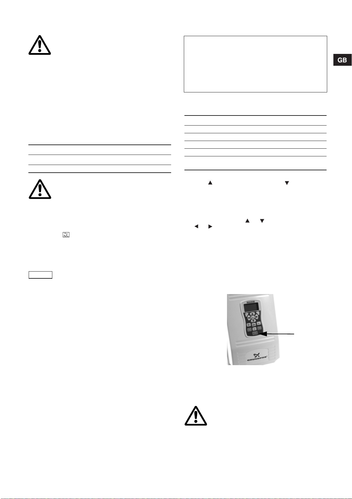
6.1 Aufstellen des Frequenzumrichters 19
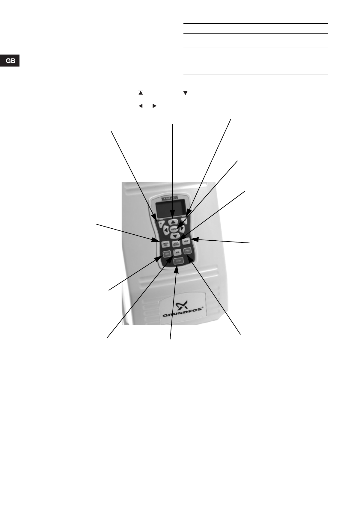
6.2 Tasten am Frequenzumrichter 20
7. Elektrischer Anschluss 21
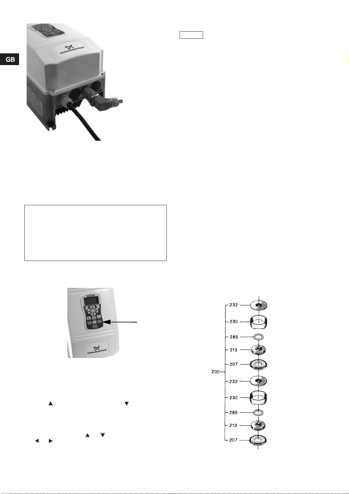
7.1 Anschluss des Frequenzumrichters 21
7.2 Generatorbetrieb 21
7.3 Vorgehensweise zum Starten des Generatorbetriebs 21
7.4 Vorgehensweise zum Beenden des Generatorbetriebs 21
7.5 Anschluss der Pumpe 22
8. Inbetriebnahme und Betrieb 22
8.1 Inbetriebnahme 22
8.2 Betrieb 22
9. Wartung und Service 22
9.1 Wartung 22
9.2 Service 23
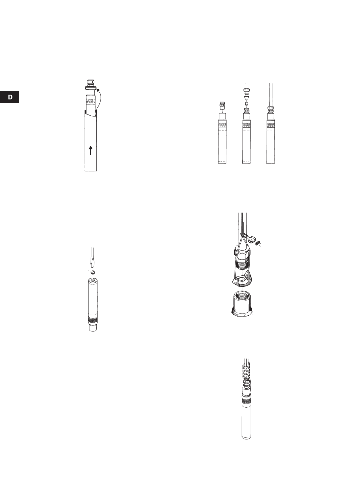
10. Demontage und Montage 23
10.1 Beschreibung und Übersicht des MP 1 Probenahme-
Pumpensystems 23
10.2 Demontage der Pumpe 24
10.3 Kontrolle der Komponenten 24
10.4 Montage der Pumpe 25
11. Störungen, Ursachen und Abhilfe 26
11.1 Wiederinbetriebnahme nach Störungen 26
11.2 Störmeldungen am Frequenzumrichter 26
12. Entsorgung 26
1. Sicherheitshinweise
Diese Montage- und Betriebsanleitung enthält grundlegende Hin-
weise, die bei Aufstellung, Betrieb und Wartung zu beachten
sind. Sie ist daher unbedingt vor Montage und Inbetriebnahme
vom Monteur sowie dem zuständigen Fachpersonal/Betreiber zu
lesen. Sie muss ständig am Einsatzort der Anlage verfügbar sein.
Es sind nicht nur die unter diesem Abschnitt "Sicherheitshin-
weise" aufgeführten, allgemeinen Sicherheitshinweise zu beach-
ten, sondern auch die unter den anderen Abschnitten eingefüg-
ten, speziellen Sicherheitshinweise.
1.1 Kennzeichnung von Hinweisen
Direkt an der Anlage angebrachte Hinweise wie z.B.
• Drehrichtungspfeil
• Kennzeichnung für Fluidanschlüsse
müssen unbedingt beachtet und in vollständig lesbarem Zustand
gehalten werden.
1.2 Personalqualifikation und -schulung
Das Personal für Bedienung, Wartung, Inspektion und Montage
muss die entsprechende Qualifikation für diese Arbeiten aufwei-
sen. Verantwortungsbereich, Zuständigkeit und die Überwachung
des Personals müssen durch den Betreiber genau geregelt sein.
1.3 Gefahren bei Nichtbeachtung der Sicherheits-
hinweise
Die Nichtbeachtung der Sicherheitshinweise kann sowohl eine
Gefährdung für Personen als auch für die Umwelt und Anlage zur
Folge haben. Die Nichtbeachtung der Sicherheitshinweise kann
zum Verlust jeglicher Schadenersatzansprüche führen.
Im einzelnen kann Nichtbeachtung beispielsweise folgende
Gefährdungen nach sich ziehen:
• Versagen wichtiger Funktionen der Anlage
• Versagen vorgeschriebener Methoden zur Wartung und
Instandhaltung
• Gefährdung von Personen durch elektrische und mechani-
sche Einwirkungen.
1.4 Sicherheitsbewusstes Arbeiten
Die in dieser Montage- und Betriebsanleitung aufgeführten
Sicherheitshinweise, die bestehenden nationalen Vorschriften zur
Unfallverhütung sowie eventuelle interne Arbeits-, Betriebs- und
Sicherheitsvorschriften des Betreibers, sind zu beachten.
1.5 Sicherheitshinweise für den Betreiber/Bediener
• Ein vorhandener Berührungsschutz für sich bewegende Teile
darf bei einer sich in Betrieb befindlichen Anlage nicht ent-
fernt werden.
• Gefährdungen durch elektrische Energie sind auszuschließen
(Einzelheiten hierzu siehe z.B. in den Vorschriften des VDE
und der örtlichen Energieversorgungsunternehmen).
1.6 Sicherheitshinweise für Wartungs-, Inspektions-
und Montagearbeiten
Der Betreiber hat dafür zu sorgen, dass alle Wartungs-, Inspek-
tions- und Montagearbeiten von autorisiertem und qualifiziertem
Fachpersonal ausgeführt werden, das sich durch eingehendes
Studium der Montage- und Betriebsanleitung ausreichend infor-
miert hat.
Grundsätzlich sind Arbeiten an der Pumpe nur im Stillstand
durchzuführen. Die in der Montage- und Betriebsanleitung
beschriebene Vorgehensweise zum Stillsetzen der Anlage muss
unbedingt eingehalten werden.
Unmittelbar nach Abschluss der Arbeiten müssen alle Sicher-
heits- und Schutzeinrichtungen wieder angebracht bzw. in Funk-
tion gesetzt werden.
Achtung
Die in dieser Montage- und Betriebsanleitung
enthaltenen Sicherheitshinweise, die bei Nicht-
beachtung Gefährdungen für Personen hervor-
rufen können, sind mit dem allgemeinen
Gefahrensymbol "Sicherheitszeichen nach
DIN 4844-W00" besonders gekennzeichnet.
Achtung
Dieses Symbol finden Sie bei Sicherheitshinwei-
sen, deren Nichtbeachtung Gefahren für die
Maschine und deren Funktionen hervorrufen
kann.
Hinweis Hier stehen Ratschläge oder Hinweise, die das
Arbeiten erleichtern und für einen sicheren
Betrieb sorgen.

16
1.7 Eigenmächtiger Umbau und Ersatzteilherstellung
Umbau oder Veränderungen an Pumpen sind nur nach Abspra-
che mit dem Hersteller zulässig. Originalersatzteile und vom Her-
steller autorisiertes Zubehör dienen der Sicherheit. Die Verwen-
dung anderer Teile kann die Haftung für die daraus entstehenden
Folgen aufheben.
1.8 Unzulässige Betriebsweisen
Die Betriebssicherheit der gelieferten Pumpen ist nur bei bestim-
mungsgemäßer Verwendung entsprechend Abschnitt
2.1 Verwendungszweck der Montage- und Betriebsanleitung
gewährleistet. Die in den technischen Daten angegebenen
Grenzwerte dürfen auf keinen Fall überschritten werden.
2. Allgemeines
Die Unterwasserpumpe MP 1 wurde speziell zum schnellen
Abpumpen und zur Beprobung von Grundwasserbeschaffenheits-
messstellen mit einem Innendurchmesser von mindestens 50 mm
entwickelt.
Die Pumpe wird über einen regelbaren Frequenzumrichter im
Frequenzbereich von 25 bis 400 Hz angetrieben. Bei 400 Hz
bedeutet dieses eine Fördermenge von 1 m3/h bei einer Förder-
höhe von 74 m.
Abb. 1 Unterwasserpumpe MP 1 und Frequenzumrichter
Pumpe und Motor bilden eine komplette Einheit, die zum Reini-
gen oder für Servicezwecke leicht zu demontieren ist.
Das PTFE-Kabel ist in verschiedenen Längen lieferbar.
2.1 Verwendungszweck
Die Pumpe MP 1 eignet sich zur Förderung und Probenahme von
verunreinigtem Wasser.
Der maximale Sandgehalt des Wassers darf 50 g/m3nicht über-
steigen. Ein größerer Sandgehalt reduziert die Lebensdauer der
Verschleißteile und erhöht die Gefahr einer Blockierung der
Pumpe.
Wassertemperatur: +1 °C bis +30 °C.
Alle Einzelteile der Pumpe sind aus Werkstoffen hergestellt, die
keine Fremdstoffe an das Fördermedium abgeben. Eine Beein-
flussung oder Verfälschung von Wasserproben ist daher nicht
gegeben.
Um das Reinigen der Pumpe zu vermeiden und eine potentielle
Gefahr der Übertragung von Verunreinigungen von einem Bohr-
loch zum anderen (Cross-Contamination) zu eliminieren, emp-
fiehlt es sich, die Pumpe fest zu installieren.
Es ist möglich, dieselbe Pumpe in verschiedenen Grundwasser-
beschaffenheitsmessstellen zu verwenden, wenn eine Cross-
Contamination ausgeschlossen werden kann.
Falls eine Flüssigkeit mit einer von Wasser abweichenden Dichte
und/oder kinematischen Zähigkeit gefördert wird, steigt die
Leistungsaufnahme des Motors im Verhältnis zur Bemessungs-
leistung, und die maximale Drehzahl muss reduziert werden.
2.2 Technische Daten
2.2.1 Pumpe MP 1
2.2.2 Frequenzumrichter
2.2.3 Förderleistung
Pumpenkennlinien der MP 1, siehe Abb. A auf Seite 60.
2.2.4 Abmessungen
Maßskizzen, siehe Abb. B, C und D auf Seite 61.
Achtung Die Pumpe darf nur über den dazugehörigen
Frequenzumrichter betrieben werden.
Siehe Abb. 1.
Gr3101 - GrA6096
Achtung Die Pumpe MP 1 ist nicht für die Förderung von
konzentrierten Ölen oder Chemikalien sowie
explosiven Medien ausgelegt.
Hinweis Beim Einsatz der Pumpe MP 1 sind die einschlä-
gigen Unfallverhütungsvorschriften und die örtli-
chen Bestimmungen zu beachten.
Achtung
Die Pumpe MP 1 wurde nicht für Dauerbetrieb,
z.B. Abhilfepumpen, entwickelt. Der Einsatz der
Pumpe in Dauerbetrieb wird unter Umständen die
Lebensdauer der Pumpe beeinträchtigen.
Kennzeichnung: Das MP 1 Probenahme-Pumpen-
system ist CE-gekennzeichnet.
Leistungsaufnahme: 1,3 kW.
Spannung: 3 x 220 V, 400 Hz.
Max. Strom: 5,5 A.
Motorschutz: Eingebauter Thermoschalter.
Wassertemperatur: 0 °C bis +35 °C.
Anschlussgewinde: Rp 3/4.
Dauerbetrieb: Max. 500 Stunden.
Nettogewicht: 2,5 kg.
Versorgungsspannung: 1 x 220-240 V – 15 %/+ 10 %,
50/60 Hz, PE.
Min. Generatorgröße: Mit Spannungsregelung:
•2,5kVA.
• 4,0 kVA (empfohlene Größe).
Ohne Spannungsregelung:
5,0 kVA.
Nennstrom: 10 A (bei max. Ausgangsstrom).
Max. Ausgangsstrom: 9,6 A (Begrenzung durch Motor-
schutz, siehe weiter unten).
Sicherung: 10 A.
Leistungsfaktor: 0,65.
Anschlusskabel: 3 x 1,5 mm2, 3 m mit Stecker.
Ausgangsspannung: 3 x 15,4 V, 25 Hz, bis
3 x 235 V, 400 Hz.
Motorschutz: Eingebauter Überstromschutz,
auf 6,1 A eingestellt.
Beschleunigungszeit: 0 bis 400 Hz: Max. 6 Sek.
Verzögerungszeit: 400 bis 0 Hz: Max. 6 Sek.
Schutzart: IP 65.
Umgebungstemperatur: –10 °C bis 45 °C.
Relative Luftfeuchtig-
keit: Max. 95 %.
Nettogewicht: 7,7 kg.

17
3. Sicherheit
3.1 Sicherheitshinweise
3.1.1 Explosionsgefahr
Das Pumpensystem ist nicht als explosionsgeschützt klassifi-
ziert. Daher müssen örtliche Vorschriften beachtet bzw. Behör-
den konsultiert werden, falls Zweifel besteht, ob das Pumpensys-
tem verwendet werden darf.
3.1.2 Persönliche Sicherheitsausrüstung
Bei der Förderung von Wasser mit gefährlichen Inhaltsstoffen
muss persönliche Sicherheitsausrüstung verwendet werden.
3.1.3 Garantie
Die Grundfos Garantie erstreckt sich auf Pumpen, die in Überein-
stimmung mit dieser Anleitung und nach dem neuesten Stand der
Technik installiert sind.
Jede Manipulation am Pumpensystem führt zum Erlöschen der
Gewährleistung. Für daraus entstehende Folgeschäden kann
Grundfos nicht haftbar gemacht werden.
3.1.4 Elektrischer Anschluss
Bei der Montage/dem Ziehen der Pumpe ist darauf zu achten,
dass das Motorkabel nicht beschädigt wird. Der elektrische
Anschluss muss in Übereinstimmung mit den örtlichen Vorschrif-
ten des EVU bzw. VDE vorgenommen werden.
3.1.5 Service
Siehe Abschnitt 9.2 Service.
4. Transport und Lagerung
4.1 Lieferung
4.1.1 Pumpe MP 1
Die Pumpe MP 1 ist nach der Produktion ultraschallgereinigt und
in einem Polyäthylenbeutel verpackt. Das bedeutet, dass die
Pumpe nach der Reinigung weder mit Schmutz, Reinigungs-
mitteln oder ähnlichen Mitteln noch mit Menschenhänden in
Berührung gewesen ist.
4.1.2 Frequenzumrichter
4.2 Lagerung
Das Pumpensystem ist in einem sauberen und trockenen Raum
zu lagern.
4.2.1 Pumpe MP 1
Lagertemperatur: –20 °C bis +50 °C.
Falls die Pumpe nach Gebrauch gelagert werden soll, muss sie
zuerst sorgfältig gereinigt werden. Siehe Abschnitt 9. Wartung
und Service.
4.2.2 Frequenzumrichter
Der Frequenzumrichter ist in einem sauberen und trockenen
Raum zu lagern.
Lagertemperatur: –10 °C bis +45 °C.
5. Installation
5.1 Montage
Die Pumpe kann sowohl vertikal als auch horizontal eingebaut
werden. Das Anschlussgewinde der Pumpe darf sich jedoch nie
unter der horizontalen Lage befinden. Siehe Abb. 2.
Abb. 2 Einbauanforderungen
Die Pumpe muss während des Betriebs vollständig im Wasser
eingetaucht sein.
Die Leistung der Pumpe wird durch Änderung der Frequenz
geregelt. Die Montage eines Ventils in der Druckleitung ist daher
unnötig und direkt unzweckmäßig, was die Qualität der Wasser-
probe betrifft.
Falls ein Ventil dennoch montiert wird, muss sichergestellt wer-
den, dass die Pumpe nur kurzzeitig gegen das geschlossene
Ventil läuft. Falls die Pumpe für längere Zeit gegen das geschlos-
sene Ventil läuft, wird die erzeugte Wärme eine Abschaltung der
Pumpe verursachen.
Falls ein Rückschlagventil in der Druckleitung montiert werden
soll, ist dieses unbedingt mindestens 0,5 m über der Pumpe zu
montieren. Somit wird sichergestellt, dass die in der Pumpe
befindliche Luft beim Eintauchen der Pumpe so komprimiert wer-
den kann, dass die Pumpe bei der Inbetriebnahme teilweise mit
Wasser gefüllt ist.
Achtung
Während des Einsatzes (Handlings), Betriebes,
Transportes und der Lagerung sind die jeweiligen
Umweltschutzverordnungen und örtlichen
Bestimmungen über den Umgang mit gefähr-
lichen Stoffen zu befolgen.
Bei der Außerbetriebnahme der Pumpe muss
sichergestellt werden, dass sich keine Reste
eventuell gefährlicher Stoffe in der Pumpe befin-
den, um zu verhindern, dass eine Gesundheits-
oder Umweltgefahr entsteht.
Der Motor ist flüssigkeitsgefüllt (ca. 25 ml demi-
neralisiertes Wasser). Während des Betriebs wird
diese Flüssigkeit ganz oder teilweise gegen das
Fördermedium ausgetauscht und kann daher eine
potentielle Verunreinigung- und Vergiftungs-
gefahr darstellen.
Das abgepumpte Wasser kann verunreinigt und/
oder vergiftet sein. Deshalb sind die Bestimmun-
gen für gefährliche Stoffe unbedingt zu befolgen.
Achtung
Der Motorkabelstecker darf nur am Frequenz-
umrichter montiert/demontiert werden, wenn die
Versorgungsspannung zum Umrichter abgeschal-
tet ist.
Pumpen, die nicht kontaminierte Wässer geför-
dert haben, können zur Wartung an Grundfos
zurückgesandt werden, wenn sie mit einer
Unbedenklichkeitsbescheinigung versehen sind.
Achtung
Der Frequenzumrichter darf keinen unnötigen
Erschütterungen ausgesetzt und muss wie ein
empfindliches elektronisches Gerät behandelt
werden.
TM00 1168 4692
Erlaubt
Nicht erlaubt

18
5.2 Brunnendurchmesser
Der Innendurchmesser der Grundwasserbeschaffenheitsmess-
stelle muss mindestens 50 mm betragen. Es empfiehlt sich,
Grundwasserbeschaffenheitsmessstellen vor ihrer erstmaligen
Beprobung mit einem Kaliber auf freien Durchgang zu prüfen.
Falls der Innendurchmesser des zu beprobenden Brunnens
größer als 80 mm ist, kann die Pumpe in einem Kühlmantel
montiert werden, um unbeabsichtigte Abschaltungen zu ver-
hindern. Siehe Abb. 3.
Abb. 3 MP 1 im Kühlmantel
5.3 Wasserspiegel
Der dynamische Wasserspiegel (abgesenkte Wasserspiegel) darf
maximal 80 m betragen.
5.4 Kontrolle der Motorflüssigkeit
Die Motorflüssigkeit ist vor dem Einbau der Pumpe zu prüfen.
1. Die Pumpe vertikal mit dem Anschlussgewinde nach unten
(d.h. Boden des Motors nach oben) stellen und die Einfüll-
schraube entfernen. Siehe Abb. 4.
Abb. 4 Demontieren der Einfüllschraube
2. Falls das Wasser bis zum Rand der Bohrung steht, ist kein
Nachfüllen der Flüssigkeit erforderlich.Falls das nicht der Fall
ist, ist demineralisiertes Wasser einzufüllen.
Um sicherzustellen, dass die Luft entweichen kann, muss die
Welle ein paar Male mit dem Finger durch den Pumpendruck-
stutzen bewegt werden.
Flüssigkeitsmenge evtl. nochmals prüfen.
3. Einfüllschraube wieder einsetzen und fest anziehen.
Die Pumpe kann jetzt installiert werden.
5.5 Rohrleitungsanschluss
Anschlussgewinde der Pumpe: Rp 3/4.
Rohre oder Schläuche können an die Pumpe angeschlossen
werden.
Wenn ein Schlauch montiert wird, muss eine Quetschkupplung
verwendet werden. Siehe Abb. 5.
Überwurfmutter mit der Hand bis zum Anschlag anziehen und
danach weitere 1 1/4 Umdrehungen mit einem Werkzeug fest-
ziehen.
Abb. 5 Verwenden einer Quetschkupplung
Falls Rohre oder Schläuche aus PTFE oder unarmierte Schläu-
che verwendet werden, ist ein zusätzliches Stahlseil aus Edel-
stahl zu montieren.
Befestigung des Stahlseils an der Pumpe mittels Sicherungs-
blech. Siehe Abb. 6.
Abb. 6 Befestigen des Stahlseils
Die Befestigung des Kabels und des eventuell montierten
Stahlseils am Steigrohr/-schlauch der Pumpe muss mittels
Spiralflex oder Kabelbinder in 1 bis 3 m Abstand erfolgen.
Siehe Abb. 7.
Abb. 7 Spiralflex
TM00 0898 4092TM00 1173 4092
TM00 0901 4092TM00 0875 4092TM00 1147 4092

19
5.6 Absenkung der Pumpe
Die Pumpe muss vorsichtig ins Bohrloch so abgesenkt werden,
dass das Motorkabel nicht beschädigt wird.
5.7 Eintauchtiefe
Während des Betriebs müssen Pumpe und Motor immer vollstän-
dig im Wasser eingetaucht sein, damit die Wellenabdichtung ein-
wandfrei geschmiert und der Motor gekühlt wird.
Falls die Pumpenleistung größer ist als der Zulauf des Wassers
zum Brunnen, besteht die Gefahr, dass der Wasserspiegel bis
unter das Einlaufteil der Pumpe abgesenkt wird und die Pumpe
dadurch Luft ansaugt.
Falls ein Rückschlagventil in der Druckleitung montiert werden
soll, ist dieses unbedingt mindestens 0,5 m über der Pumpe zu
montieren. Somit wird sichergestellt, dass die in der Pumpe
befindliche Luft beim Eintauchen der Pumpe so komprimiert wer-
den kann, dass die Pumpe bei der Inbetriebnahme teilweise mit
Wasser gefüllt ist.
6. Frequenzumrichter
6.1 Aufstellen des Frequenzumrichters
Der Frequenzumrichter ist vertikal aufzustellen, damit Kühlluft
das Gerät frei umströmen kann. Siehe Abb. 8.
Es ist sicherzustellen, dass der Koffer/der Frequenzumrichter
während des Betriebs nicht umkippen kann.
Abb. 8 Vertikale Aufstellung des Frequenzumrichters
Achtung Die Pumpe darf nicht am Motorkabel gezogen
werden.
Achtung Längere Betriebszeit mit lufthaltigem Wasser
kann Beschädigung der Pumpe und ungenü-
gende Kühlung des Motors verursachen.
Achtung Den Frequenzumrichter mit Koffer so aufstellen,
dass kein Wasser in den Koffer eindringen kann.
Den Koffer während des Betriebs nicht schließen.
GrA6096

20
6.2 Tasten am Frequenzumrichter
Die Tasten am Frequenzumrichter dienen zum Ändern von
Regelparametern, zum Betreiben der MP 1 Pumpe und zum
Navigieren zwischen den Bildschirmseiten, um den Betriebssta-
tus der Pumpe zu überwachen.
In einigen Tasten sind Meldeleuchten integriert.
Abb. 9 Tasten am Frequenzumrichter
* Mögliche Displaytexte, siehe Seite 62.
Meldeleuchte Beschreibung
[FWD]-Taste (grün) Die Meldeleuchte leuchtet, wenn der
Motor vorwärts läuft.
[REV]-Taste (grün) Die Meldeleuchte leuchtet, wenn der
Motor rückwärts läuft.
[STOP]-Taste (rot) Die Meldeleuchte leuchtet, wenn die
Taste [STOP] gedrückt wurde.
GrA6103
[STOP]
Die Taste [STOP] drücken, um
den Motor abzuschalten.
[JOG]
Die Taste [JOG] ist deakti-
viert.
[REV]
Die Taste [REV] drücken, um
die Drehrichtung des Motors
umzukehren.
[FWD]
Die Taste [FWD] drücken, um die
Pumpe einzuschalten (der Motor
dreht vorwärts).
[HELP]
Zeigt einen Hilfetext für jeden
Displaytext, jeden Einstell-
parameter und jede Störung
an*.
Die Taste [HELP] drücken,
um die Hilfefunktion zu
öffnen/schließen.
[LOCAL/REMOTE]
Am Frequenzumrichter muss
immer der Modus LOCAL einge-
stellt sein.
[ENTER]
Im Anzeigemodus dient die Taste
[ENTER] zum direkten Einstellen der
gewünschten Drehzahl.
[F2]
Zum Zurücksetzen des Frequenz-
umrichters die Taste [F2] drücken.
Pfeiltasten
Die Taste [ ] drücken, um den Wert des ange-
zeigten Parameters zu erhöhen und die Taste [ ]
drücken, um den Wert des angezeigten Parame-
ters zu reduzieren.
Die Taste [ ] oder [ ] drücken, um zwischen den
Ziffern zu wechseln.
[F1]
Die Taste [F1] drücken, um in den
Programmiermodus zu gelangen.
Der Frequenzumrichter ist werksei-
tig voreingestellt.
DIE WERKSEINSTELLUNG
NICHT ÄNDERN!
[MENU/ESC]
Durch Drücken der Taste
[MENU/ESC] wird ein Menü
mit sechs Unterpunkten
geöffnet:
STATUS
QUICK SETUP
PROGRAMMING
EVENT LOG
DIAGNOSTICS
DISPLAY OPTIONS
Die Taste [MENU/ESC]
erneut drücken, um zum
vorherigen Bildschirm
zurückzukehren.
Table of contents
Languages:
Popular Water Pump manuals by other brands

Etatron
Etatron HD-MA Operating Instructions, Maintenance

Thermaltake
Thermaltake Pacific PR22-D5 Plus user manual

Agilent Technologies
Agilent Technologies X3502-64170 user manual

Jet
Jet R750 manual

Bijur Delimon
Bijur Delimon FZ-B operating instructions

Gude
Gude MP 120/5A 24 LT Translation of the original instructions

Einhell Royal
Einhell Royal SPU 16/1 operating instructions

Aquatight
Aquatight Saturn Series Installation and operation manual

Simplex
Simplex P140D operating instructions

Graco
Graco E-Flo SP D200S INSTALLATION AND PARTS MANUAL

Grundfos
Grundfos MTH Series Installation and operating instructions

Eckerle
Eckerle EE400 installation instructions