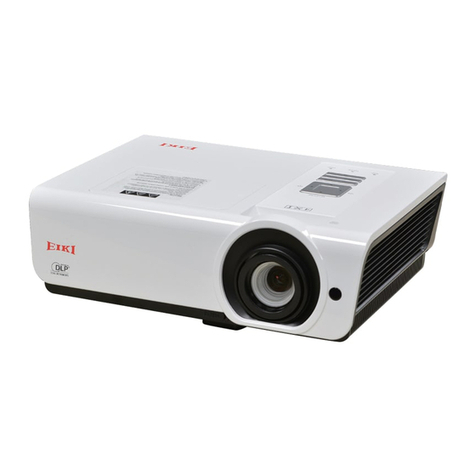
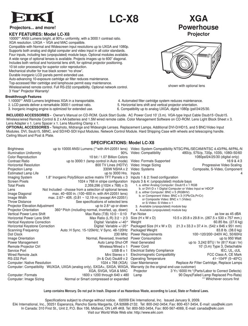
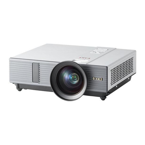
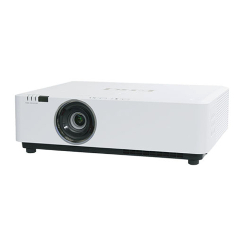
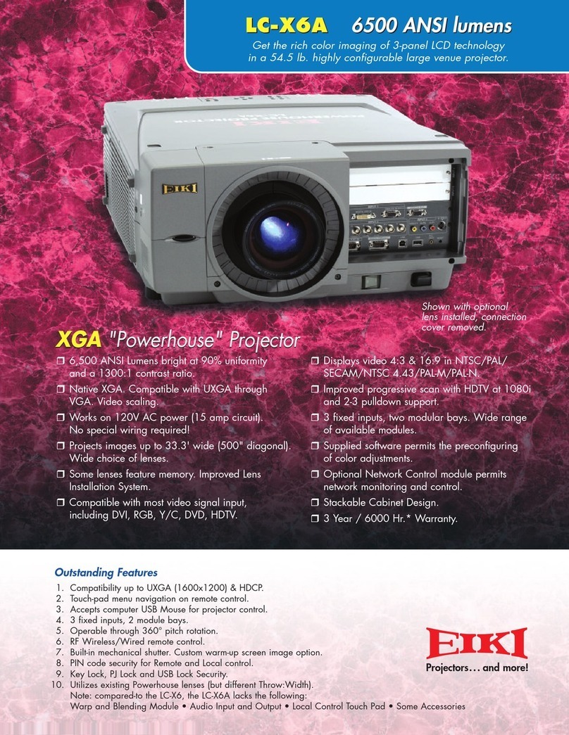
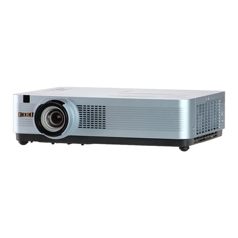
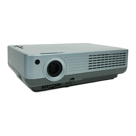
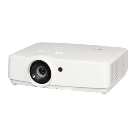
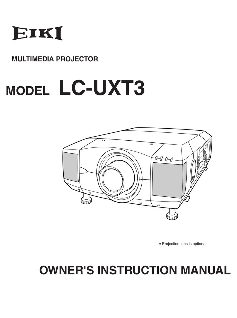
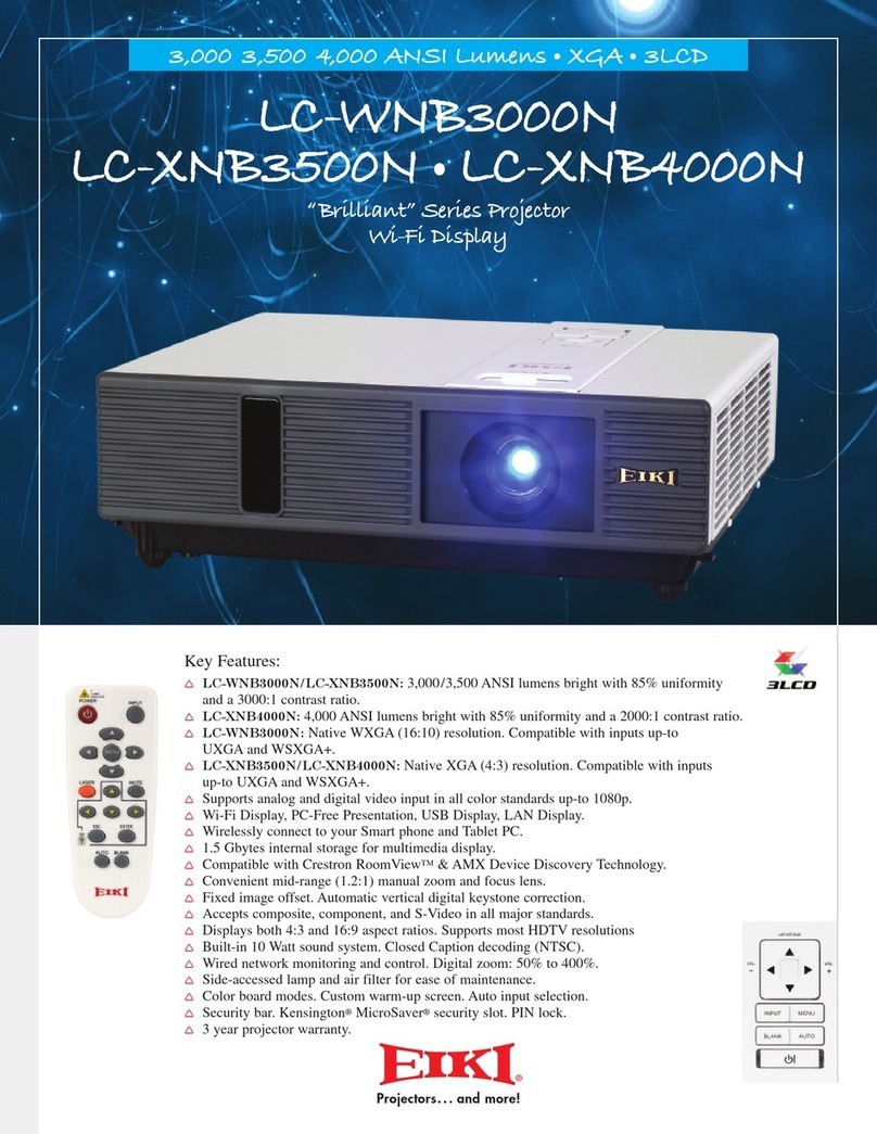
Eiki LC-XT6 User manual

* Projection lens is optional.
Multimedia Projector
SERVICE MANUAL
Model No. LC-XT6
US, Europe
FOREWORD
For your convenience, all service parts, identified in this manual are available through Eiki’s normal distribution channels.
In addition to service part number, the generic descriptions have been given, where possible, to allow your service
technicians to substitute equivalent components which might be available from other sources.
All orders for service parts will be honored. However, in instances where generic components are considered to be
available from several common sources, as would be the case with an industry standard fuse, resistor, or semicon-
ductor, it may be more economical and expeditious to purchase the part locally.
(2 012 -11) REFERENCE NO. SMA1211008E-00

-2-
Contents
SERVICE MANUAL ................................................... 1
Contents ........................................................................ 2
Safety Instructions......................................................... 3
Safety Precautions ..........................................................3
Product Safety Notice .....................................................3
Service Personnel Warning.............................................3
Specifications ................................................................ 5
Circuit Protections ....................................................... 10
Fuses (F601, F602, F603).............................................10
Thermal fuses (SW903, SW904, SW905, SW906)....... 11
Temperature sensors, wind sensors .............................12
Power failure, fan lock and filter error detection ............ 13
Maintenance................................................................ 14
Maintenance.................................................................. 14
Replacing the unit.......................................................... 14
Air filter unit ................................................................... 14
Lamp unit....................................................................... 17
Quick maintenance .......................................................21
Cleaning the optical parts..............................................22
Security Function Notice ............................................. 23
Lens Mounting............................................................. 24
Mechanical Disassembly............................................. 32
Order of mechanical disassembly.................................32
Optical Parts Disassembly .......................................... 51
Order of optical parts disassembly................................ 51
Servicing Notice .......................................................... 65
Note on main board replacement..................................65
Adjustment data setting.................................................65
Serial number setting ....................................................65
Model no. setting...........................................................65
Adjustments................................................................. 66
Adjustments after parts replacement ............................66
Optical Adjustments .................................................... 67
Optical adjustment location...........................................67
Before adjustment .........................................................68
1. Optical center adjustment..........................................70
2. PBS adjustment......................................................... 74
3. Contrast adjustment .................................................. 75
4. Back focus adjustment .............................................. 76
5. Convergence adjustment ..........................................77
Adjustment tool installation ...........................................78
Adjustment tool removal................................................79
Adjustment ....................................................................80
Electrical Adjustments................................................. 81
Service adjustment menu operation .............................81
Circuit adjustments........................................................82
Test points and locations...............................................86
Service adjustment data................................................87
Chassis Description .................................................. 158
Chassis over view........................................................158
Boards connection ...................................................... 159
Troubleshooting......................................................... 160
No picture .................................................................... 160
No Power.....................................................................164
Power supplies to boards ............................................ 165
AC filter, AC-DC power board...................................... 166
DC power board .......................................................... 167
PFC-1 & PFC-2 board .................................................168
Power supply and power failure detection................... 169
Power drive and power failure signals......................... 172
Fan control system ...................................................... 173
Motor control system ................................................... 174
Temperature abnormality ............................................ 175
Lamp abnormality........................................................ 176
Lamp control system ................................................... 177
Power failure detection system ................................... 178
Error history log ........................................................... 179
Diagnosis of power failure with serial port...................180
Indicators and projector condition ............................... 181
Serial Control............................................................. 185
Serial control interfaces...............................................185
Control Port Functions............................................... 188
IC Block Diagrams..................................................... 191
Exploded Views & Parts List ..................................SPL-1
Exploded Views..................................................... SPL-2
Mechanical Parts List .......................................... SPL-20
Electrical Parts List...............................................SPL-23
Schematic Diagram & Circuit Board Diagram........ DIA-1
Pin description of diode, transistor and IC ...............DIA-2
Schematic Diagram ................................................DIA-3
Circuit Board Diagram .......................................... DIA-15
-3-
Safety Instructions
WARNING:
The chassis of this projector is isolated (COLD) from AC line by using the converter transformer. Primary side
of the converter and lamp power supply unit circuit is connected to the AC line and it is hot, which hot circuit is
identified with the line ( ) in the schematic diagram. For continued product safety and protection of per-
sonnel injury, servicing should be made with qualified personnel.
The following precautions must be observed.
Safety Precautions
1: An isolation transformer should be connected in
the power line between the projector and the AC
line before any service is performed on the projec-
tor.
2: Comply with all caution and safety-related notes
provided on the cabinet back, cabinet bottom, inside
the cabinet or on the chassis.
3: When replacing a chassis in the cabinet, always
be certain that all the protective devices are
installed properly, such as, control knobs, adjust-
ment covers or shields, barriers, etc.
DO NOT OPERATE THIS PROJECTOR WITHOUT
THE PROTECTIVE SHIELD IN POSITION AND PR
OPERLY SECURED.
4: Before replacing the cabinet cover, thoroughly
inspect the inside of the cabinet to see that no stray
parts or tools have been left inside.
Before returning any projector to the customer, the
service personnel must be sure it is completely safe
to operate without danger of electric shock.
Service Personnel Warning
Eye damage may result from directly viewing the light produced by the Lamp used in this equipment. Always
turn off Lamp before opening cover. The Ultraviolet radiation eye protection required during this servicing.
Never turn the power on without the lamp to avoid electric-shock or damage of the devices since the stabilizer
generates high voltages (15kV - 25kV) at its starts.
Since the lamp is very high temperature during units operation replacement of the lamp should be done at least
45 minutes after the power has been turned off, to allow the lamp cool-off.
Product Safety Notice
Product safety should be considered when a component replacement is made in any area of the projector.
Components indicated by mark !in the parts list and the schematic diagram designate components in which
safety can be of special significance. It is, therefore, particularly recommended that the replacement of there
parts must be made by exactly the same parts.

-4-
<PT-FW430U/PT-FW430E/PT-FW430EA/PT-FX400U/PT-FX400E/PT-FX400EA>
1. Safety Precautions
1.1. General Guidelines
1.2. Leakage Current Check
1. Prepare the measuring circuit as shown in Fig.1.
Be sure to use a voltmeter having the performance described in Table 1.
2. Assemble the circuit as shown in Fig. 2. Plug the power cord in a power outlet.
3. Connect M1 to T1 according to Fig. 2 and measure the voltage.
4. Change the connection of M1 from T1 to T2 and measure the voltage again.
5. The voltmeter must read 0.375 V or lower in both of steps 3 and 4. This means that the current must be 0.75mA or less.
6. If the reading is out of the above standard, the projector must be repaired and rechecked before returning to the customer
because of a possibility of an electric shock.
- For continued safety, no modification of any circuit must be attempted.
- Unplug the power cord from the power outlet before disassembling this projector.
- Use correctly the supplied power cord and must ground it.
- It is advisable to use an isolation transformer in the AC power line before the service.
- Be careful not to touch the rotation part (cooling fan, etc.) of this projector when you service with the upper
case removed and the power supply turned ON.
- Observe the original lead dress during the service. If a short circuit is found, replace all the parts overheated
or damaged by the short circuit.
- After the service, all the protective devices such as insulation barriers, insulation papers, shields, and isolation
R-C combinations must be properly installed.
- After the service, check the leakage current to prevent the customer from getting an electric shock.
4
1.3. UV Precaution and UHM Lamp Precautions
- Be sure to unplug the power cord from the power outlet when replacing the lamp.
- Because the lamp reaches a very high temperature during its operation, wait until it cools completely when replacing
the Lamp Unit.
- The lamp emits small amounts of UV-radiation, avoid direct-eye contact with the light.
- The lamp unit has high internal pressure. If improperly handled, explosion might result.
- Because the high pressure lamp involves a risk of failure, never touch the lamp wire lead during the service.
Fig. 1 Fig. 2
Table. 2
4
Safety Instructions

-5-
Specifications
Model No. LC-XT6
Power supply AC 200 V - 240 V 50 Hz/60 Hz
Power consumption
200 V - 240 V 11 A 1 850 W
When [Lamp power] in the [Setting] menu is set to eco-mode: 1 450 W
Standby: 18 W
LCD panel
Size 4.57 cm (1.8”) (aspect ratio 4:3)
Display sys-
tem Three transparent LCD panels (RGB)
Drive system Polysilicon TFT active matrix system
Number of
pixels 786 432 pixels (1 024 x 768 dots) x 3 panels
Luminous lamp 380 W UHM lamp x 4
Light output 16 000 lm (when [lamp select] is set to [4-Lamps] and [Lamp power] is set to stan-
dard)
Image signals that can be pro-
jected Refer to “List of compatible signals”
Color system Six standards (NTSC/NTSC4.43/PAL/PAL-N/PAL-M/SECAM)
Screen size 1.02 m (40”) – 15.24 m (600”)
Screen aspect ratio 4:3
Projection method Front / Rear / Mount on Ceiling / Floor (Menu setting system)
Contrast ratio 2 500:1 (when setting [Lamp power] to auto, and [Advanced color] to [Auto])
Terminals
INPUT 1
DVI-D input
terminal
1 set, DVI-D 24 p
Digital signal TMDS (Transition Minimized Differential Signaling)
HDMI input
terminal 1 set, HDMI 19 pin (HDCP, Deep color compliant)
COMPUTER
input terminal
1 set (D-sub 15 p (female))
RGB signal 0.7 V [p-p] 75Ω(G-SYNC: 1.0 V [p-p] 75Ω)
HD/SYNC TTL high impedance, automatic positive/neg-
ative polarity compatible
VD, TTL high impedance, automatic positive/negative
polarity compatible
INPUT 2
Analog RGB
input terminal
1 set (BNC 5 p)
RGB signal 0.7 V [p-p] 75Ω(G-SYNC: 1.0 V [p-p] 75Ω) HD/SYNC
TTL high impedance, automatic positive/negative polar-
ity compatible
VIDEO signal 1.0 V [p-p] 75Ωnegative sync
Y PB/CBPR/CRsignal Y: 1.0 V [p-p] negative sync, PB/CB: 0.7 V [p-p] 75Ω, PR/
CR: 0.7 V [p-p] 75Ω
S-VIDEO input
terminal 1 set, Mini DIN 4 p Y 1.0 V [p-p], C 0.286 V [p-p] 75ΩS1 signal compliant
Serial input terminal D-Sub 9 p 1 set, RS-232C-compatible computer control
USB terminal (used by
service personnel) US connector (1 set, series B)
Wired remote control Mini jack
LAN terminal 1 set, RJ-45 for network connection, PJLink compliant, 10Base-T/100Base-TX
The following table describes the specifications of the projector.

-6-
Specifications
Model No. LC-XT6
Power cable length 3.0 m (118-1/8”)
Outer case Molded plastic
Dimensions Width: 650 mm (25-5/8”) Height: 349 mm (13-3/4”) (feet fully retracted)
Depth: 815 mm (32-1/8”) (feet fully retracted, not including lens)
Weight Approx. 46.5 kg (102.5 lbs.)
Operating environment Operating environment temperature*1: 5°C (41°F) to 40°C (104°F)
Operating environment humidity: 20% to 80% (no condensation)
Remote
control
Power supply DC 3 V (AAA battery x 2)
Operating range Approx. 5 m (196-7/8”) (within 30º in each direction)
Weight 102 g (3.6 ozs.) (including batteries)
Dimensions Width: 48 mm (1-7/8”) Height: 27 mm (1-1/8”) Depth: 145 mm (5-3/4”)
*1: The operating environment temperature may differ depending on the type of air filter used and when using the projector at
high elevations.
• The product numbers of accessories and separately sold components are subject to change without notice.

-7-
Specifications
7HFKQLFDO,QIRUPDWLRQ
(1*/,6+
$SSHQGL[
/LVWRIFRPSDWLEOHVLJQDOV
7KHIROORZLQJWDEOHVSHFL¿HVWKHW\SHVRIVLJQDOFRPSDWLEOHZLWKWKHSURMHFWRU
■:KHQWKHVLJQDOLVDQDORJ
6FUHHQGLVSOD\ 5HVROXWLRQ 6FDQQLQJIUHTXHQF\ 'RWFORFN
PRGH GRWV +RUL]RQWDON+] 9HUWLFDO+] IUHTXHQF\0+]
9*$ [
9*$ [
9*$ [
9*$ [
9*$ [
9*$ [
9*$ [
0$&/& [
0$& [
S [
S [
L [L
L [L
69*$ [
69*$ [
69*$ [
69*$ [
69*$ [
69*$ [
69*$ [
69*$ [
69*$ [
69*$ [
69*$ [
0$& [
;*$ [
;*$ [
;*$ [
;*$ [
;*$ [
;*$ [
;*$ [
;*$ [
;*$ [L
;*$ [
;*$ [
;*$ [L
;*$ [
;*$ [
;*$ [
0$& [
6;*$ [
6;*$ [
6;*$ [
6;*$ [
6;*$ [
6;*$ [
6;*$ [
6;*$ [
6;*$ [
6;*$ [
6;*$ [
6;*$ [
6;*$ [L
6;*$ [L
6;*$ [
6;*$ [

-8-
Specifications
7HFKQLFDO,QIRUPDWLRQ
(1*/,6+
$SSHQGL[
6FUHHQGLVSOD\ 5HVROXWLRQ 6FDQQLQJIUHTXHQF\ 'RWFORFN
PRGH GRWV +RUL]RQWDON+] 9HUWLFDO+] IUHTXHQF\0+]
6;*$ [
6;*$ [L
6;*$ [
6;*$ [
6;*$ [
6;*$ [
6;*$ [
6;*$ [
6;*$ [
6;*$ [
6;*$ [
0$& [
0$& [
0$& [
:;*$ [
:;*$ [
:;*$ [
:;*$ [
:;*$ [
:;*$ [
:;*$ [
:;*$ [
:;*$ [
:;*$ [
:;*$ [
:;*$ [
:;*$ [
:;*$ [
:;*$ [
:;*$ [
:;*$ [
:8;*$ [
:8;*$ [
:6;*$ [
:;*$ [
:;*$ [
8;*$ [
8;*$ [
8;*$ [
8;*$ [
8;*$ [
S [
S [
L [L
L [L
[L
S
[
[
[
[
[
SVI [
SVI [
SVI [
7KH³L´DIWHUWKHUHVROXWLRQLQGLFDWHVDQLQWHUODFHGVLJQDO
1RWFRPSDWLEOHZLWK>7UXH@LQ>6FUHHQ@

-9-
Specifications
7HFKQLFDO,QIRUPDWLRQ
(1*/,6+
$SSHQGL[
■:KHQWKHVLJQDOLVGLJLWDO
6FUHHQGLVSOD\ 5HVROXWLRQ 6FDQQLQJIUHTXHQF\ 'RWFORFN
PRGH GRWV +RUL]RQWDON+] 9HUWLFDO+] IUHTXHQF\0+]
'9*$ [
'L [
'L [
'S [
'S [
'69*$ [
';*$ [
':;*$ [
':;*$ [
':;*$ [
':;*$ [
':;*$ [
':;*$ [
':;*$ [
':;*$ [
':;*$ [
':;*$ [
':;*$ [
':;*$ [
':;*$ [
':;*$ [
':;*$ [
':;*$ [
':;*$ [
':;*$ [
'6;*$ [
'6;*$ [
'6;*$ [
'6;*$ [
'6;*$ [
'6;*$ [
'6;*$ [
'6;*$ [
'6;*$ [
'8;*$ [
':8;*$ [
':6;*$ [
':;*$ [
'S [
[
'L [L
'L [L
[L
'SVI [
'SVI [
'SVI [
'S
[
[
[
[
[
7KH³L´DIWHUWKHUHVROXWLRQLQGLFDWHVDQLQWHUODFHGVLJQDO
2QO\FRPSDWLEOHZLWKVLJQDOVXVLQJDQ+'0,FDEOHFRQQHFWHGWRWKH+'0,,1!WHUPLQDO
1RWH
z7KHQXPEHURIGLVSOD\GRWVLV[
z$VLJQDOZLWKDGLIIHUHQWUHVROXWLRQZLOOEHSURMHFWHGDIWHUFRQYHUWLQJWKHUHVROXWLRQWRPDWFKWKHSURMHFWRUGLVSOD\
z:KHQLQWHUODFHGVLJQDOVDUHFRQQHFWHGWKHUHPD\EHÀLFNHULQJLQWKHSURMHFWHGLPDJH
z7KHSURMHFWRULVQRWFRPSDWLEOHZLWKVLJQDOVZLWKDGRWFORFNIUHTXHQF\RI0+]RUKLJKHU

-10-
This projector provides the following circuit protections to operate in safety. If the abnormality occurs inside the pro-
jector, it will automatically turn off by operating one of the following protection circuits.
Circuit Protections
Fuses are located inside of the projector. If all the indicators are not lighting,
the fuse (F602) may be opened. If the STAND-BY indicator is lighting and
others are blinking, one of the fuses (F601, F603) may be opened. If fuse
(F601. F603) opens, the power supply to the LAMP1/LAMP2, or LAMP3/
LAMP4 will be cut off.
Check the fuses as following steps.
The fuses should be used with the following type;
Location : F601 / F603
Fuse Part No. : K5E802BZA003
TYPE 8.0A 250V FUSE
0215008.MXEP, LITTEL
How to replace the fuses
1. Remove the cabinet top, main board, PFC/Ballast box1-2
following to "Mechanical disassembly".
2. Remove the fuses F601, F602 and F603 on the AC filter
board.
To install the fuses, take reversed step in the above.
Fuses (F601, F602, F603)
F603
F602 F601
Location : F602
Fuse Part No. : K5E632BZA003
TYPE 6.3A 250V FUSE
021506.3MXEP, LITTEL
AC filter board

-11-
Circuit Protections
There are the thermal fuses (SW903, SW904, SW905 and SW906) inside of
the projector to detect the internal temperature rising abnormally. When the
internal temperature around lamps reaches near 99˚C, the thermal fuse will
open to cut off the power supply to the lamp power circuit.
If one of the thermal fuses opens, the projector cannot turn on the lamps. If
the STAND-BY indicator is lighting and others are blinking, one of the ther-
mal fuses may be opened. Thermal fuse replacement is required. The re-
placement of the thermal fuses must be done with a set of 4 fuses at once.
SW903
Thermal fuses (SW903, SW904, SW905, SW906)
SW904
SW905
SW906

-12-
The projector provides 2 temperature sensor ICs, 1 sensor on the main board and 1 sensor on the ex temp board,
and 1 wind sensor on the intake duct. The sensor ICs monitor surrounding temperature of the panels/prism, and
surrounding temperature of the intake duct, and the wind sensor monitors airflow passed through the air filter in the
intake duct.
- Temperature sensor (IC8851) on the main board for monitoring the surrounding temperature of B-panel.
- Temperature sensor (IC8811) on the ex temp board for monitoring the surrounding temperature of the intake duct.
- Wind sensor (S901) on the filter box.
Circuit Protections
IC8851
(Behind)
Temperature sensors, wind sensors
S901
Wind sensor
IC8811
The projector is shut down and the WARNING TEMP. indica-
tor is blinking red.
When the temperature inside the projector reaches a certain level, the WARN-
ING TEMP. indicator starts blinking. If the temperature rises moreover, the
projector will be automatically shut down to protect the inside of the projector,
and the WARNING TEMP. indicator is blinking fast and the POWER indicator
turns off. When the projector has cooled down enough (to its normal operat-
ing temperature), the POWER indicator turns on and the projector can be
turned on again by pressing the ON/STAND-BY button.
✔Note:
• The WARNING TEMP. indicator continues to blink even after the tempera-
ture inside the projector returns to normal. When the projector is turned on
again, the WARNING TEMP. indicator stops blinking.
Indicators
WARNING TEMP.
blinking red
Check the items below
- Remove dust around the air filter.
- Ventilation slots of the projector are blocked. In such an event, reposition the
projector so that ventilation slots are not obstructed.
- Check if projector is used at higher temperature place (Norma; operating
temperature is 5 to 40 ºC or 41 to 104 ºF).

-13-
The projector provides the detection circuits of the power failure and the fan lock. When the detection circuit detects
an error at the power supply line or at the fan operation circuit, the projector will turn into the standby mode to protect
the other circuits defective.
Circuit Protections
Power failure, fan lock and filter error detection
CAUTION
DO NOT LEAVE THE PROJECTOR WITH THE AC POWER CORD
CONNECTED UNDER AN ABNORMAL CONDITION. IT MAY RE-
SULT IN FIRE OR ELECTRIC SHOCK.
Indicators
The projector is shut down; and the STAND-BY indicator is
lighting and other indicators are blinking.
When the projector detects an abnormal condition (Power supply lines failure
, fans failure), it will be automatically shut down to protect the inside of the
projector and the STAND-BY indicator lights on and other indicators blink. In
this case, unplug the AC power cord and plug it, and then turn on the projec-
tor once again to verify operation. If the projector cannot be turned on and
these indicators are still lighting and blinking, unplug the AC power cord. See
the troubleshooting chapter.
STAND-BY indicator lights
on and other indicators
blink.

-14-
Before replacing the unit
When maintaining or replacing the unit, always turn off the power and remove the power plug from the outlet.
Maintenance
nOuter case
Wipe off dirt and dust with a soft, dry cloth.
• If the dirt is persistent, soak the cloth with water and wring it thoroughly before wiping. Dry off the projector with
a dry cloth.
• Do not use solvents such as benzene, thinner, rubbing alcohol, household cleaners, or chemical wipes. Using
them may cause deterioration of the outer case.
nFront surface of the lens
Wipe off dirt and dust off the front surface of the lens with a soft, dry, and clean cloth.
• Do not use a cloth that is fluffy, dusty, or soaked with oil/water.
• Do not use excessive force when wiping the lens as it is fragile.
Attention
• Lenses are made of glass. Impacts or excessive force when wiping may scratch its surface. Please handle with
care.
• Never use flammable solvents or air sprays on or around the projector. The temperature within the projector
may be extremely hot due to the projection lamp operation. An explosion or fire may still occur even after turn-
ing off the projector. Other than flammable air spray, the internal parts may also become damaged due to cold
air.
Replacing the unit
Filter prevents dust from accumulating on the optical elements inside the projector. Should the filter become
clogged with dust particles, it will reduce cooling fans’ effectiveness and may result in internal heat buildup and
adversely affect the life of the projector. If a “Filter warning” icon appears on the screen, replace the filters im-
mediately.
nReplacement of the air filter
1) Pull out the air filter unit.
• Use a Phillips screwdriver to turn the screws counterclockwise until they turn freely, and then remove the air
filter unit.
Screws
Air filter unit
Maintenance

-15-
Maintenance
2) Remove the holder.
• Loosen the three screws on the holder (A, B), slide the holder in the direction shown by the arrow in the im-
age, and lift up to remove the holder.
3) Remove the air filter.
• Hook your fingers in the slot to lift up and remove the air filter.
4) Attach the new air filter.
• Inserting the new air filter by slowly sliding it will make it easier to attach.
• The side with the sponge must be the top. Attaching it with the wrong side up or forcing it to attach will cause
the air to leak in. The air filter does not work fully and as a result, dust will get into the projector.
5) Attach the holder.
• Place the holder (A, B) on top of the filter.
• Slide the holder so that its arrows line up with the arrows on the unit, and attach the holder.
• Tighten the three holder screws.
6) Attach the air filter unit to the projector.
• Perform step 1) in the reverse order.
7) Reset the filter counter.
• Turn on the power and perform [Filter counter reset] in the [Setting] menu.
Attention
• Make sure to turn off the power before replacing the air filter.
• When attaching the unit, make sure that the projector is stable. Perform the replacement in a safe place where
the projector will not be damaged even if you drop the air filter unit.
• When turning the projector on, make sure that the air filter unit is installed before using the projector. Failure to
do so may cause damage.
• Air filters cannot be reused.
• The air filter and unit cannot be washed in water. Make sure not to wet the air filter with water or any other liquid.
Doing so may cause damage.
• After replacing the air filter, reset the filter counter. Otherwise, the power of the projector may be turned off for
safety.
• After attaching the air filter unit, be sure to tighten the screws. If not, the air filter unit may drop off while project-
ing.
Holder B
Screws Holder A

-16-
Maintenance
Be sure to reset the filter counter after replacing the
filters.
Press the MENU button to display the On-Screen
Menu. Use the Point ed buttons to select [Setting]
and then press the Point 8button or the SELECT
button.
Use the Point ed buttons to select [Filter counter]
and the press the SELECT button. Use the Point ed
buttons to select [Filter counter reset] and the press
the SELECT button. Filter counter Reset? appears.
Select [Yes] to continue.
1
2
nResetting the filter counter
Filter counter
“Filter counter Reset?”
appears.
Select [Yes], then
another confirmation box
appears.
Select [Yes] again to
reset the Filter counter.
Another confirmation dialog box appears, select [Yes]
to reset the Filter counter.
3
Select “Used time” and the dia-
logue box below appears.
✔Note:
• Whenever the filters have been replaced, reset the Filter
counter, but if the filters were not replaced, do not reset
the filter counter, as this could cause product damage.

-17-
Maintenance
Lamp unit
The lamp unit is a consumable component. Check the lamp usage duration with “[Information] menu” and perform
regular replacement.
If the replacement message is displayed on the screen and the lamp indicators <LAMP 1 REPLACE> to
<LAMP 4 REPLACE> turn on, replace the lamp units.
Replacement lamp POA-LMP147.
Attention
• Do not replace the lamp unit until it has cooled down sufficiently. (Wait at least 60 minutes after use.) The inside
of the cover is very hot and may cause burns.
nNotes on the replacement of the lamp unit
The lamp unit is a consumable component. Replace the lamp unit regularly, as its brightness gradually decreases
over time. The estimated duration before replacement is 2 000 hours (when [Lamp power] is set to standard).
However, this may be shortened depending on individual lamp characteristics, usage conditions, and the installa-
tion environment. Earlier replacement of lamp units is recommended for this reason.
The duration exceeds 2 200 hours of usage for two lamps, the lamps will be switched to the other two lamps if
they are available. After switching, if the duration exceeds 2 200 hours of usage for one of the two lamps and the
lamp fails, only the other lamp will light.
If the power is turned on without replacing the lamps after the duration exceeds 2 200 hours of usage for all lamps,
the power automatically turns off after approximately ten minutes to prevent the malfunction of the projector.
• Since the luminous lamp is made of glass, it may burst if dropped or hit with a hard object. Please handle with
care.
• A Phillips screwdriver is necessary when replacing the lamp unit.
• When replacing the lamp unit, be sure to hold it by the handle.
• The lamp contains mercury. When disposing of the used lamp unit, ask your nearest local authorities or dealer
about proper disposal of the unit.
Attention
• Use only specified lamp units.
• The product numbers of accessories and separately sold components are subject to change without notice.
• Replacement of all four lamps simultaneously is recommended to ensure a balance brightness and tint.
On-screen display Lamp indicator
<LAMP REPLACE>
Lamp indicators
<LAMP 1 REPLACE> to
<LAMP 4 REPLACE>
The lamp replacement instructions
notify the replacement time, and the
lamp status notifies which lamp to
replace.
Turns orange. Turns orange to notify which
lamp to replace.
nWhen to replace the lamp unit

-18-
Maintenance
Attention
• Turn off the UV lamp before opening the lamp cover.
• When the projector is mounted on the ceiling, do not put your face near the lamp unit.
• Attach the lamp unit securely.
• If the lamp unit is not attached properly, remove it and then attach it again. Forcing the lamp unit in may break
the connector.
• The glass surface may be hot. When replacing the lamp unit, be sure to hold it by the handle.
1) Check which lamp to replace with the lamp status displayed on the screen, or the lamp indicators
<LAMP 1 REPLACE> to <LAMP 4 REPLACE>.
2) Turn off the power and disconnect the power plug from the power outlet, and wait at least 60 minutes,
and then check if the lamp unit has cooled down.
3) Use a Phillips screwdriver to turn the lamp cover fixing screw on top of the projector body until they
turn freely, and then open the lamp cover.
• Open the cover until it is at 90° to the projector.
Lamp status Lamp indicators <LAMP 1 REPLACE> to
<LAMP 4 REPLACE>
Lamp cover
Screw
nReplacing the lamp unit

-19-
Maintenance
4) Use a Phillips screwdriver to turn the lamp unit fixing screws (two screws) until they turn freely, and
then holding the handle, slowly pull out the lamp unit from the projector.
5) Insert the new lamp unit taking note of its direction, and use a Phillips screwdriver to firmly tighten the
lamp unit fixing screws (two screws).
• Do not smear the glass surface by touching it with your hand.
6) Close the lamp cover, and use a Phillips screwdriver to firmly tighten the lamp cover fixing screw.
Note
• When replacing with the new lamp unit, the projector resets the total usage time of the lamp unit automatically.
• After replacing the lamp unit, be sure to tighten the lamp cover fixing screw. If not, the lamp unit may drop off
while projecting
Lamp unit
Screw
TURN OFF THE UV LAMP BEFORE OPENING THE LAMP COVER
To prevent glass fragments from scattering, hold the lamp unit vertically when replacing it. When the
projector is attached to the ceiling, do not work directly under the lamp cover or put your face near it.
Remove the lamp cover slowly.
LAMP NO. : POA-LMP147

-20-
Maintenance
nChecking the projector used time and lamp used time
The LAMP REPLACE indicator will light yellow when the total lamp used time (Corresponding value) reaches
2,000 hours. This is to indicate that lamp replacement is required.
The total lamp used time is calculated by using the below expression,
Total lamp used time (Corresponding value) = Teco x 0.67 + Tnormal
Teco : used time in the Eco 1 and Eco 2 mode
Tnormal : used time in the Normal mode and Auto mode
You can check the lamp used time following to the below procedure.
1Press and hold the ON/STAND-BY button on the projector or the ON button on the remote control for more
than 20 seconds.
2The projector used time and lamp used time will be displayed on the screen briefly as follows.
Counter
Projector 500H
Lamp Lamp 1 Lamp 2 Lamp 3 Lamp 4
Normal 200 H 100 H 200 H 100 H
Eco 300 H 300 H 300 H 300 H
Corresponding value 400 H 300 H 300 H 450 H
Projector used time
Lamp 4 Total lamp used time
Lamp 3 Total lamp used time
Lamp
control Auto Normal Eco 1 Eco 2
Normal ✔ ✔
Eco ✔ ✔
Lamp used time table in the Lamp
control - Lamp mode
nWarning message on the non-standard lamp used
If the non-standard lamp is used, the warning and confirmation messages will appear on the screen every startup.
Some of the functions are limited when the non-standard lamp is used in spite of the warning.
Since the lamp is not standard,
projector failed to read lamp data.
Continue to use this lamp?
Yes
No
Lamp 2 Total lamp used time
Lamp 1 Total lamp used time
Other manuals for LC-XT6
2
Table of contents
Other Eiki Projector manuals

Eiki
Eiki EK-623U series User manual

Eiki
Eiki LC-XB28 User manual

Eiki
Eiki LC-XT2 Setup guide

Eiki
Eiki LC-XIP2000 User manual

Eiki
Eiki OHP-4100A User manual

Eiki
Eiki DLP Projector EIP-5000 User manual

Eiki
Eiki EK-100 series User manual

Eiki
Eiki LC-SVGA860 Setup guide

Eiki
Eiki 392 User manual

Eiki
Eiki LC-SX2 Setup guide