EIS STM32-H4Q7 User manual

Distributor of Olimex LTD: Excellent Integrated System Limited
Datasheet of STM32-H407 - ST M3 STM32F407 HEADER BOARD
Excellent Integrated System Limited
Excellent Integrated System Limited
Stocking Distributor
Stocking Distributor
Click to view price, real time Inventory, Delivery & Lifecycle Information:
Click to view price, real time Inventory, Delivery & Lifecycle Information:
Olimex LTD
Olimex LTD
STM32-H407
STM32-H407
For any questions, you can email us directly:
For any questions, you can email us directly:
1 / 31
1 / 31

Distributor of Olimex LTD: Excellent Integrated System Limited
Datasheet of STM32-H407 - ST M3 STM32F407 HEADER BOARD
STM32-H407 development board
USER’S MANUAL
Document revision E, May 2016
Designed by OLIMEX Ltd, 2012
All boards produced by Olimex LTD are ROHS compliant
2 / 31
2 / 31
Distributor of Olimex LTD: Excellent Integrated System Limited
Datasheet of STM32-H407 - ST M3 STM32F407 HEADER BOARD
OLIMEX© 016 STM3 -H407 user's manual
D SCLA MER
© 016 Olimex Ltd. Olimex®, logo and combinations thereof, are registered trademarks of Olimex Ltd. Other product
names may be trademarks of others and the rights belong to their respective owners.
The in ormation in this document is provided in connection with Olimex products. No license, express or implied
or otherwise, to any intellectual property right is granted by this document or in connection with the sale o
Olimex products.
This work is licensed under the Creative Commons Attribution-ShareAlike 3.0 Unported License. To view a copy of
this license, visit http://www.creativecommons.org/licenses/by-sa/3.0/.
This hardware design by Olimex LTD is licensed under a Creative Commons Attribution-ShareAlike 3.0 Unported
License.
The software is released under GPL.
It is possible that the pictures in this manual differ from the latest revision of the board.
The product described in this document is subject to continuous development and improvements. All particulars of the
product and its use contained in this document are given by OLIMEX in good faith. However all warranties implied or
expressed including but not limited to implied warranties of merchantability or fitness for purpose are excluded. This
document is intended only to assist the reader in the use of the product. OLIMEX Ltd. shall not be liable for any loss or
damage arising from the use of any information in this document or any error or omission in such information or any
incorrect use of the product.
This evaluation board/kit is intended for use for engineering development, demonstration, or evaluation purposes only
and is not considered by OLIMEX to be a finished end-product fit for general consumer use. Persons handling the
product must have electronics training and observe good engineering practice standards. As such, the goods being
provided are not intended to be complete in terms of required design-, marketing-, and/or manufacturing-related
protective considerations, including product safety and environmental measures typically found in end products that
incorporate such semiconductor components or circuit boards.
Olimex currently deals with a variety of customers for products, and therefore our arrangement with the user is not
exclusive. Olimex assumes no liability for applications assistance, customer product design, software performance, or
infringement of patents or services described herein.
THERE IS NO WARRANTY FOR THE DESIGN MATERIALS AND THE COMPONENTS
USED TO CREATE STM32-H407. THEY ARE CONSIDERED SUITABLE ONLY FOR
STM32-H407.
Page of 30
3 / 31
3 / 31
Distributor of Olimex LTD: Excellent Integrated System Limited
Datasheet of STM32-H407 - ST M3 STM32F407 HEADER BOARD
OLIMEX© 016 STM3 -H407 user's manual
Table of Contents
D SCLA MER ............................................................................................................. 2
CHAPTER 1 OVERV EW ......................................................................................... 5
1. Introduction to the chapter ....................................................................................................... 5
1.1 Features ..................................................................................................................................... 5
1.2 H407 or E407? .......................................................................................................................... 6
1.3 Target market and purpose o the board ............................................................................... 6
1.4 Organization ............................................................................................................................. 6
CHAPTER 2 SETT NG UP THE STM32-H407 BOARD ....................................... 7
2. Introduction to the chapter ....................................................................................................... 7
2.1 Electrostatic warning ............................................................................................................... 7
2.2 Requirements ........................................................................................................................... 7
2.3 Powering the board .................................................................................................................. 8
2.4 Prebuilt so tware ...................................................................................................................... 8
CHAPTER 3 STM32-H407 BOARD DESCR PT ON ............................................ 9
3. Introduction to the chapter ....................................................................................................... 9
3.1 Layout (top view) ..................................................................................................................... 9
3.2 Layout (bottom view) ............................................................................................................. 10
CHAPTER 4 THE STM32F407ZGT6 M CROCONTROLLER ......................... 11
4. Introduction to the chapter ..................................................................................................... 11
4.1 The STM32F407ZGT6 eatures ............................................................................................ 11
CHAPTER 5 CONTROL C RCU TY AND HARDWARE MODULES ............. 13
5. Introduction to the chapter ..................................................................................................... 13
5.1 Reset ........................................................................................................................................ 13
5.2 Clocks ...................................................................................................................................... 13
CHAPTER 6 CONNECTORS AND P NOUT ....................................................... 14
6. Introduction to the chapter ..................................................................................................... 14
6.1 JTAG/SWD debug ................................................................................................................. 14
6.2 SD/MMC slot .......................................................................................................................... 14
6.3 UEXT module ......................................................................................................................... 15
6.4 USB HOST .............................................................................................................................. 16
6.5 USB_OTG ............................................................................................................................... 16
6.6 Arduino plat orm ................................................................................................................... 16
6.7 20-pin connectors – PD – PE – PF – PG .............................................................................. 18
6.8 PWR Jack ............................................................................................................................... 19
6.9 Battery connector ................................................................................................................... 19
6.10 U3BOOT ............................................................................................................................... 19
6.11 Jumper description .............................................................................................................. 19
Page 3 of 30
4 / 31
4 / 31
Distributor of Olimex LTD: Excellent Integrated System Limited
Datasheet of STM32-H407 - ST M3 STM32F407 HEADER BOARD
OLIMEX© 016 STM3 -H407 user's manual
6.11.1 PWR_SEL ................................................................................................................................ 19
6.11.2 B1_1/B1_0 and B0_1/B0_0 ...................................................................................................... 20
6.11.3 R-T ............................................................................................................................................ 20
6.11.4 3.3V_E ....................................................................................................................................... 20
6.11.5 AGND_E ................................................................................................................................... 20
6.11.6 AREF_EN ................................................................................................................................. 21
6.12 Additional hardware components ...................................................................................... 21
CHAPTER 7 HOW TO USE THE BOARD W TH ARDU NO DE ................... 22
CHAPTER 8 BLOCK D AGRAM AND MEMORY ............................................. 23
8. Introduction to the chapter ..................................................................................................... 23
8.1 Processor amily block diagram ........................................................................................... 23
8.2 Physical memory map ........................................................................................................... 24
CHAPTER 9 SCHEMAT CS ................................................................................... 25
9. Introduction to the chapter ..................................................................................................... 25
9.1 Eagle schematic ...................................................................................................................... 25
9.2 Physical dimensions ............................................................................................................... 27
CHAPTER 10 REV S ON H STORY AND SUPPORT ........................................ 28
10. Introduction to the chapter ................................................................................................... 28
10.1 Document revision ............................................................................................................... 28
10.2 Board's revision .................................................................................................................... 28
10.3 Use ul web links and purchase codes ................................................................................. 29
10.4 Product support ................................................................................................................... 30
Page 4 of 30
5 / 31
5 / 31
Distributor of Olimex LTD: Excellent Integrated System Limited
Datasheet of STM32-H407 - ST M3 STM32F407 HEADER BOARD
OLIMEX© 016 STM3 -H407 user's manual
CHAPTER 1 OVERV EW
1. ntroduction to the chapter
Thank you for choosing the STM3 -H407 single board computer from Olimex! This document
provides a user’s guide for the Olimex STM3 -H407 board. As an overview, this chapter gives the
scope of this document and lists the board’s features. The differences between the members of the
OLIMEX STM3 F407 boards are mentioned. The document’s organization is then detailed.
The STM3 -H407 development board enables code development of applications running on the
microcontroller STM3 F407ZGT6, manufactured by STMicrocontrollers.
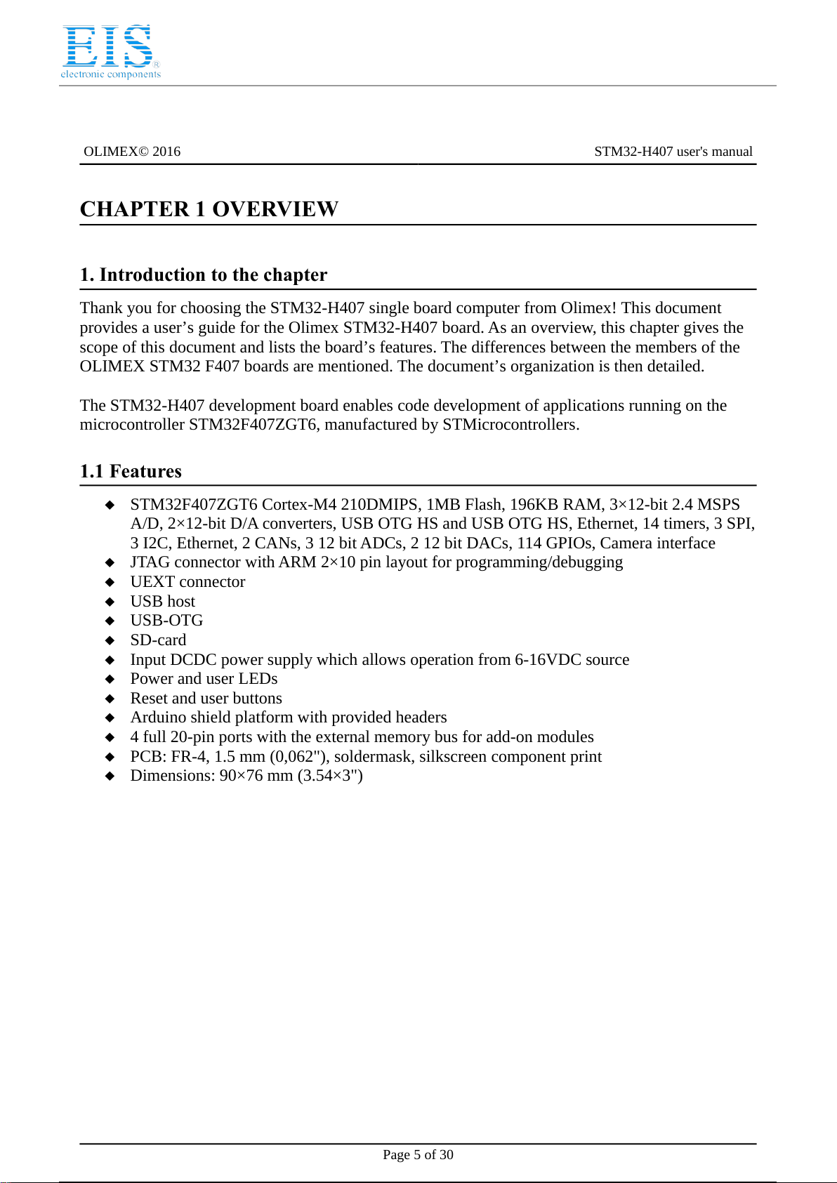
1.1 Features
STM3 F407ZGT6 Cortex-M4 10DMIPS, 1MB Flash, 196KB RAM, 3×1 -bit .4 MSPS
A/D, ×1 -bit D/A converters, USB OTG HS and USB OTG HS, Ethernet, 14 timers, 3 SPI,
3 I C, Ethernet, CANs, 3 1 bit ADCs, 1 bit DACs, 114 GPIOs, Camera interface
JTAG connector with ARM ×10 pin layout for programming/debugging
UEXT connector
USB host
USB-OTG
SD-card
Input DCDC power supply which allows operation from 6-16VDC source
Power and user LEDs
Reset and user buttons
Arduino shield platform with provided headers
4 full 0-pin ports with the external memory bus for add-on modules
PCB: FR-4, 1.5 mm (0,06 "), soldermask, silkscreen component print
Dimensions: 90×76 mm (3.54×3")
Page 5 of 30
6 / 31
6 / 31
Distributor of Olimex LTD: Excellent Integrated System Limited
Datasheet of STM32-H407 - ST M3 STM32F407 HEADER BOARD
OLIMEX© 016 STM3 -H407 user's manual
1.2 H407 or E407?
The major difference between STM3 -H407 and STM3 -E407 is that the latter has built-in
Ethernet (physical level transceiver Micrel). STM3 -E407 also features an extra USB-OTG and a
number of SMD jumpers on the bottom which help the user to control the multiplexing on some
pins easier. STM3 -E407 has x USB-OTG both with a miniUSB interface. STM3 -H407 has 1x
USB-OTG and 1x USB-HOST with the On-The-Go interfaced by miniUSB and the HOST by USB
type A connector.
If you need built-in Ethernet check the STM3 -E407.
1.3 Target market and purpose of the board
STM3 -H407 is a development board featuring a powerful ARM Cortex-M4F microcontroller with
the most important peripherals, interfaces and connectors mounted and ready to use. The board can
be powered by a number of different sources, can be programmed via two different interfaces, has a
TON of GPIO pins available on a number of headers. The board's Arduino platform headers give
another option for enthusiasts who wish to implement support for Arduino/Maple/Pinguino shields
giving the board additional features altogether with the option to add Olimex extension modules on
the OLIMEX UEXT.
All of the above options make the board quite versatile and suitable for numerous tasks and
situations. The power of ARM and the creativity of OLIMEX come at the best price and the well-
known quality.
Every ARM enthusiast would see STM3 -H407 as an interesting bargain and quite capable board
for its low price.
1.4 Organization
Each section in this document covers a separate topic, organized as follow:
–Chapter 1 is an overview of the board usage and features
–Chapter provides a guide for quickly setting up the board
–Chapter 3 contains the general board diagram and layout
–Chapter 4 describes the component that is the heart of the board: the STM3 F 07ZET6
microcontroller
–Chapter 5 is an explanation of the control circuitry associated with the microcontroller to
reset. Also shows the clocks on the board
–Chapter 6 covers the connector pinout, peripherals and jumper description
–Chapter 7 gives advice on how to use the board with Arduino IDE
–Chapter 8 shows the memory map
–Chapter 9 provides the schematics
–Chapter 10 contains the revision history, useful links and support information
Page 6 of 30
7 / 31
7 / 31

Distributor of Olimex LTD: Excellent Integrated System Limited
Datasheet of STM32-H407 - ST M3 STM32F407 HEADER BOARD
OLIMEX© 016 STM3 -H407 user's manual
CHAPTER 2 SETT NG UP THE STM32-H407 BOARD
2. ntroduction to the chapter
This section helps you set up the STM3 -H407 development board for the first time.
Please consider first the electrostatic warning to avoid damaging the board, then discover the
hardware and software required to operate the board.
The procedure to power up the board is given, and a description of the default board behavior is
detailed.
2.1 Electrostatic warning
STM3 -H407 is shipped in a protective anti-static package. The board must not be exposed to high
electrostatic potentials. A grounding strap or similar protective device should be worn when
handling the board. Avoid touching the component pins or any other metallic element.
2.2 Requirements
In order to set up the STM3 -H407 optimally, the following items are required:
- JTAG or SWD interface programmer/debugger – can power the board and gives the ability to
program/debug the board – to choose the correct programmer be sure that you are aware what
software tools you are going to use when programming STM3 -H407, and that the programmer
supports STM3 F407 processor.
Additional components can be acquired in order to increase the functionality of the board:
- External power supply
- SD-card or USB-mini cable or extensive UEXT modules are recommended but not required
- 3.7V Battery
- MOD-XXXX boards for additional features on the UEXT (RTC, TC, GSM, MP3, RS-485 among
others) – note that you will have to implement the software setup between the boards
- Arduino/Maple/Pinguino shields – every shield is hardware compatible with H407 but will not
work out-of-the-box, software implementation should be considered
Some of the suggested items can be purchased by Olimex, for instance:
ARM-USB-TINY-H – high-speed OpenOCD ARM JTAG debugger
ARM-USB-OCD-H – high-speed OpenOCD ARM JTAG debugger with buffer protection
USB-MINI-CABLE – USB mini to USB-A cable
BATTERY-LIPO1400MAH – lithium-polymer battery 1400mAh
SY0612E – power supply adapter 1 V/0.5A for iMX 33-STM3 -H407
Page 7 of 30
8 / 31
8 / 31
Distributor of Olimex LTD: Excellent Integrated System Limited
Datasheet of STM32-H407 - ST M3 STM32F407 HEADER BOARD
OLIMEX© 016 STM3 -H407 user's manual
2.3 Powering the board
The board is powered in one of the following ways: 1) by PWR jack, ) by JTAG/SWD
programmer, 3) by USB-OTG.
The PWR jack should be supplied from a 6V to 16V source with maximum current of 1A from the
power jack. Without additional components and peripherals (no microSD card mounted, nothing
connected to the USB, etc.) the typical consumption is 30mA @ 1 V. For the European customers
we sell an affordable power supply adapter 1 V/0.5A – SY0612E.
It is worth mentioning that the board can NOT be powered by the battery connector. The battery
connected keeps some of the processor's functions remain intact (hibernate) during power down but
it provides insufficient power for the board to operate properly. For example the RTC doesn't lose
the values when there is a battery connected.
2.4 Prebuilt software
Upon powering initially the board's red PWR LED and the green PWR LED should turn on.
Page 8 of 30
9 / 31
9 / 31
Distributor of Olimex LTD: Excellent Integrated System Limited
Datasheet of STM32-H407 - ST M3 STM32F407 HEADER BOARD
OLIMEX© 016 STM3 -H407 user's manual
CHAPTER 3 STM32-H407 BOARD DESCR PT ON
3. ntroduction to the chapter
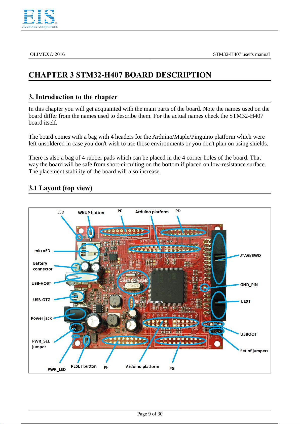
In this chapter you will get acquainted with the main parts of the board. Note the names used on the
board differ from the names used to describe them. For the actual names check the STM3 -H407
board itself.
The board comes with a bag with 4 headers for the Arduino/Maple/Pinguino platform which were
left unsoldered in case you don't wish to use those environments or you don't plan on using shields.
There is also a bag of 4 rubber pads which can be placed in the 4 corner holes of the board. That
way the board will be safe from short-circuiting on the bottom if placed on low-resistance surface.
The placement stability of the board will also increase.
3.1 Layout (top view)
Page 9 of 30
10 / 31
10 / 31
Distributor of Olimex LTD: Excellent Integrated System Limited
Datasheet of STM32-H407 - ST M3 STM32F407 HEADER BOARD
OLIMEX© 016 STM3 -H407 user's manual
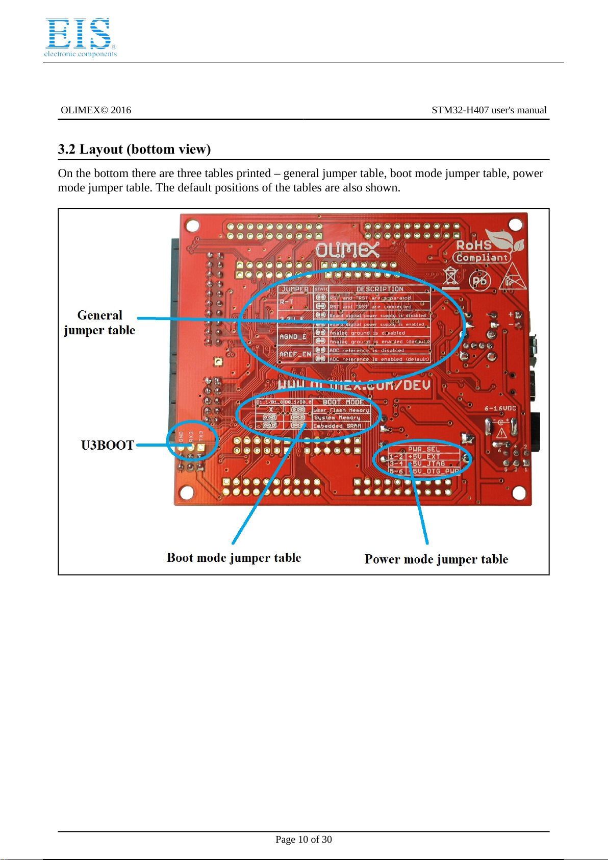
3.2 Layout (bottom view)
On the bottom there are three tables printed – general jumper table, boot mode jumper table, power
mode jumper table. The default positions of the tables are also shown.
Page 10 of 30
11 / 31
11 / 31

Distributor of Olimex LTD: Excellent Integrated System Limited
Datasheet of STM32-H407 - ST M3 STM32F407 HEADER BOARD
OLIMEX© 016 STM3 -H407 user's manual
CHAPTER 4 THE STM32F407ZGT6 M CROCONTROLLER
4. ntroduction to the chapter
In this chapter is located the information about the heart of STM3 -H407 – its Cortex-M4F
microcontroller. The information is a modified version of the datasheet provided by its
manufacturers from ST.
4.1 The STM32F407ZGT6 features
Core: ARM 3 -bit Cortex™-M4 CPU with FPU, Adaptive real-time accelerator (ART
Accelerator™) allowing 0-wait state execution from Flash memory, frequency up to 168
MHz, memory protection unit, 10 DMIPS/1. 5 DMIPS/MHz (Dhrystone .1), and DSP
instructions
Memories
1 Mbyte of Flash memory
19 +4 Kbytes of SRAM including 64-Kbyte of CCM (core coupled memory) data RAM
Flexible static memory controller supporting Compact Flash, SRAM, PSRAM, NOR
and NAND memories
LCD parallel interface, 8080/6800 modes
Clock, reset and supply management
1.8 V to 3.6 V application supply and I/Os
POR, PDR, PVD and BOR
4-to- 6 MHz crystal oscillator
Internal 16 MHz factory-trimmed RC (1% accuracy)
3 kHz oscillator for RTC with calibration
Internal 3 kHz RC with calibration
Sleep, Stop and Standby modes
VBATsupply for RTC, 0×3 bit backup registers + optional 4 KB backup SRAM
3×1 -bit, .4 MSPS A/D converters: 4 channels and 7. MSPS in triple interleaved mode
×1 -bit D/A converters
General-purpose DMA: 16-stream DMA controller with FIFOs and burst support
Up to 17 timers: up to twelve 16-bit and two 3 -bit timers up to 168 MHz, each with up to 4
IC/OC/PWM or pulse counter and quadrature (incremental) encoder input
Debug mode
Serial wire debug (SWD) & JTAG interfaces
Cortex-M4 Embedded Trace Macrocell™
114 I/O ports with interrupt capability
Up to 15 communication interfaces
3 × I C interfaces (SMBus/PMBus)
4 USARTs/ UARTs (10.5 Mbit/s, ISO 7816 interface, LIN, IrDA, modem control)
3 SPIs (37.5 Mbits/s), with muxed full-duplex I S to achieve audio class accuracy via
internal audio PLL or external clock
× CAN interfaces ( .0B Active)
SDIO interface
Advanced connectivity
USB .0 full-speed device/host/OTG controller with on-chip PHY
Page 11 of 30
12 / 31
12 / 31
Distributor of Olimex LTD: Excellent Integrated System Limited
Datasheet of STM32-H407 - ST M3 STM32F407 HEADER BOARD
OLIMEX© 016 STM3 -H407 user's manual
USB .0 high-speed/full-speed device/host/OTG controller with dedicated DMA, on-
chip full-speed PHY and ULPI
10/100 Ethernet MAC with dedicated DMA: supports IEEE 1588v hardware,
MII/RMII
8- to 14-bit parallel camera interface up to 54 Mbytes/s
True random number generator
CRC calculation unit
96-bit unique ID
RTC: subsecond accuracy, hardware calendar
For comprehensive information on the microcontroller visit the ST’s web page for a datasheet.
At the moment of writing the microcontroller datasheet can be found at the following link:
document DM00037051
Page 1 of 30
13 / 31
13 / 31

Distributor of Olimex LTD: Excellent Integrated System Limited
Datasheet of STM32-H407 - ST M3 STM32F407 HEADER BOARD
OLIMEX© 016 STM3 -H407 user's manual
CHAPTER 5 CONTROL C RCU TY AND HARDWARE MODULES
5. ntroduction to the chapter
Here you can find information about reset circuit and quartz crystals locations, the power supply
circuit is discussed.
5.1 Reset
STM3 -H407's reset circuit includes R 1 (10KΩ), R19 (1 KΩ), C35 (100nF) and a RESET button.
5.2 Clocks
There are two quartz crystals available on the board:
1 MHz quartz crystal Q1 is connected to pins 3 and 4 of the CORTEX-M4F processor.
Quartz crystal Q is a 3 768Hz RTC (real-time clock) and is connected to pins 8 and 9. 5.3 Power
supply circuit
The power supply circuit of STM3 -H407 allows flexible input supply from 6V to 16V direct
current. This means a wide range of power supplies, adapters, converters are applicable. The
maximum amperage the board can draw is 1A.
The Li-Po battery connector cannot be used to fully power the board. Its function is to give an
option to save internal data if the board needs to be relocated. It will keep the RTC alive, for
instance.
If you have successfully powered the board the red PWR LED will turn on. Note that it is possible
to have the PWR LED on even if there isn't enough power for proper operation of the board and all
the peripherals currently connected.
Page 13 of 30
14 / 31
14 / 31

Distributor of Olimex LTD: Excellent Integrated System Limited
Datasheet of STM32-H407 - ST M3 STM32F407 HEADER BOARD
OLIMEX© 016 STM3 -H407 user's manual
CHAPTER 6 CONNECTORS AND P NOUT
6. ntroduction to the chapter
In this chapter are presented the connectors that can be found on the board all together with their
pinout and notes about them. Jumpers functions are described. Notes and info on specific
peripherals are presented. Notes regarding the interfaces are given.
Note that slashed signals (xxxx/yyyy) in the tables below might mean either multiplexing between
signals or port name correspondence on the processor.
6.1 JTAG/SWD debug
The board can be debugged from the 0-pin JTAG connector either by a JTAG or a SWD
compatible debugger. Below is the table of the JTAG. This interface can be used with the Olimex's
OpenOCD debuggers.
JTAG/SWD interface
Pin # Signal
Name Pin # Signal
Name
1+3.3V 11 -
2+3.3V 12 GND
3PB4/TRST 13 PB3/TDO
4GND 14 GND
5PA15/TDI 15 PB4/TRST
6GND 16 GND
7PA13/TMS 17 -
8GND 18 GND
PA14/TCK 1 +5V_JTAG
10 GND 20 GND
6.2 SD/MMC slot
The microSD card slot is a standard 8pin connector.
We have tested a number of microSD cards on the STM3 -H407 boards and all of them worked
fine regardless manufacturer or capacity. However, keep in mind that some of the lower quality
microSD cards might draw too much current from the slot which might cause power-state problems.
If you suspect the microSD card is causing problems please try using another one of better quality
for better results.
Page 14 of 30
15 / 31
15 / 31

Distributor of Olimex LTD: Excellent Integrated System Limited
Datasheet of STM32-H407 - ST M3 STM32F407 HEADER BOARD
OLIMEX© 016 STM3 -H407 user's manual
microSD card connector
Pin # Signal Name
1DAT2/RES
2CD/DAT3/CS
3CMD/DI
4VDD
5SCL/SCLK
6VSS
7DAT0/RES
8DAT1/RES
Notice that the pad numeration is written at the bottom of STM3 -H407 under the microSD card
connector.
When removing the card, please make sure that you release it from the connector by pushing and
NOT by pulling the card directly (this can damage both the connector and the microSD card).
6.3 UEXT module
STM3 -H407 board has UEXT connector and can interface Olimex's UEXT modules.
For more information on UEXT please visit:
https://www.olimex.com/Products/Modules/UEXT/
UEXT connector
Pin # Wire Name Microcontroller port
13.3V -
2GND -
3PC6/USART6_T PC6
4PC7/USART6_R PC7
5PB8/I2C1_SCL PB8
6PB9/I2C1_SDA PB9
7PC2/SPI2_MISO PC2
8PC3/SPI2_MOSI PC3
PB10/SPI2_SCK/UART3_T PB10
10 RB7/UE T_CS PB7
Page 15 of 30
16 / 31
16 / 31
Distributor of Olimex LTD: Excellent Integrated System Limited
Datasheet of STM32-H407 - ST M3 STM32F407 HEADER BOARD
OLIMEX© 016 STM3 -H407 user's manual
6.4 USB HOST
The big advantage of having USB hosts available over USB devices is that you can as well use
them as masters. A USB host may implement multiple host controllers and each host controller may
provide one or more USB ports.
Note DFU bootloader uses the host USB port, and a "USB A-A" cable is required.
The signals follow the familiar and standard USB host pattern:
USB 2-level host
PIN# SIGNAL NAME
1+5V_HOST_PWR
2USB_HOST_D-
3USB_HOST_D+
4GND
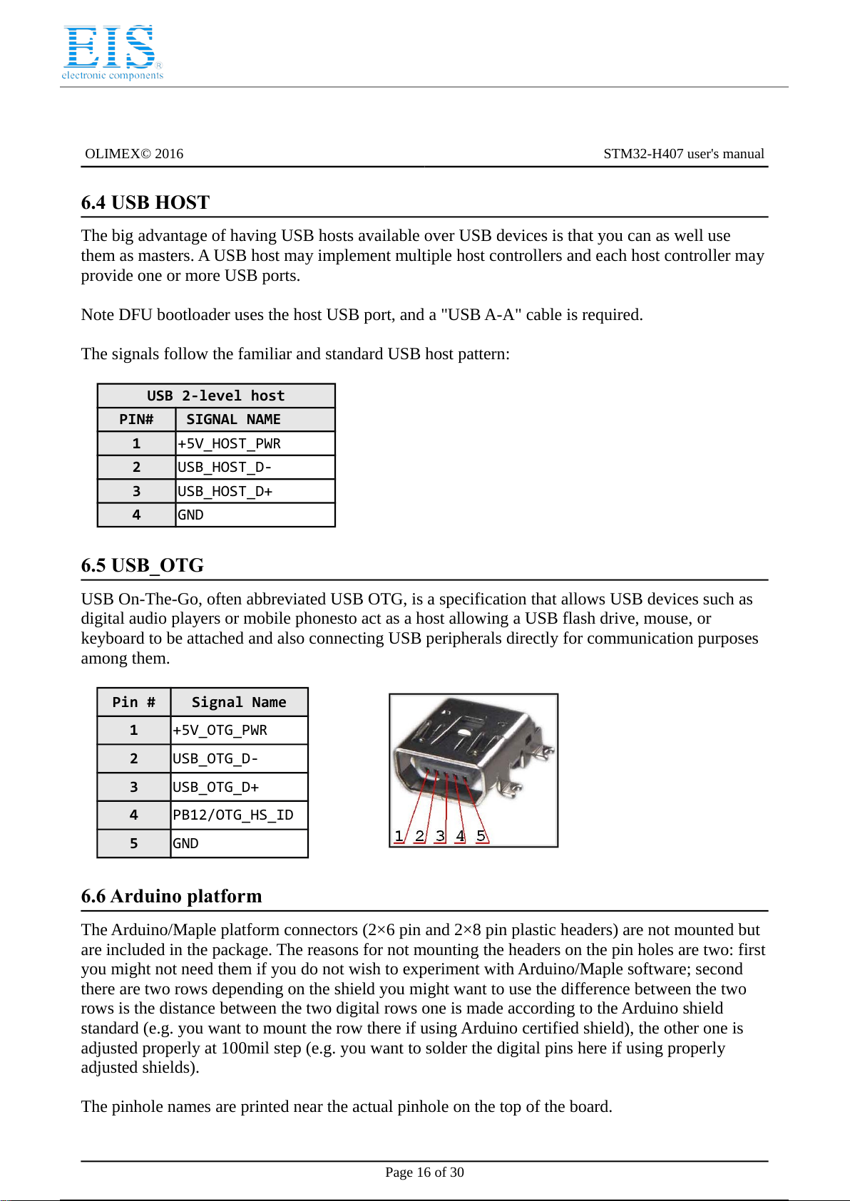
6.5 USB_OTG
USB On-The-Go, often abbreviated USB OTG, is a specification that allows USB devices such as
digital audio players or mobile phonesto act as a host allowing a USB flash drive, mouse, or
keyboard to be attached and also connecting USB peripherals directly for communication purposes
among them.
Pin # Signal Name
1+5V_OTG_PWR
2USB_OTG_D-
3USB_OTG_D+
4PB12/OTG_HS_ID
5GND
6.6 Arduino platform
The Arduino/Maple platform connectors ( ×6 pin and ×8 pin plastic headers) are not mounted but
are included in the package. The reasons for not mounting the headers on the pin holes are two: first
you might not need them if you do not wish to experiment with Arduino/Maple software; second
there are two rows depending on the shield you might want to use the difference between the two
rows is the distance between the two digital rows one is made according to the Arduino shield
standard (e.g. you want to mount the row there if using Arduino certified shield), the other one is
adjusted properly at 100mil step (e.g. you want to solder the digital pins here if using properly
adjusted shields).
The pinhole names are printed near the actual pinhole on the top of the board.
Page 16 of 30
17 / 31
17 / 31

Distributor of Olimex LTD: Excellent Integrated System Limited
Datasheet of STM32-H407 - ST M3 STM32F407 HEADER BOARD
OLIMEX© 016 STM3 -H407 user's manual
Arduino platform pinholes
CON1 CON2
Pin Signal Name Processor
pin# Pin Signal Name Processor pin#
RST RST 25 A0 PC0 26
3V3 3.3V - A1 PC1 27
5V 5V - A2 PB0 46
GND GND - A3 PB1 47
GND GND - A4 PC4 44
VIN VIN - A5 PC5 45
Arduino platform pinholes
CON3 CON4
Pin Signal Name Processor pin# Pin Signal Name Processor pin#
D0 PA3/USART_R 37 D8 PA1 35
D1 PA2/USART_T 36 D PB11 70
D2 PG7 92 D10 PA4 40
D3 PG8 93 D11 PA7 43
D4 PG12 127 D12 PA6 42
D5 PG13 128 D13 PA5 41
D6 PG14 129 GND AGND 31
D7 PG15 132 AREF AREF 32
Page 17 of 30
18 / 31
18 / 31

Distributor of Olimex LTD: Excellent Integrated System Limited
Datasheet of STM32-H407 - ST M3 STM32F407 HEADER BOARD
OLIMEX© 016 STM3 -H407 user's manual
6.7 20-pin connectors – PD – PE – PF – PG
The 4× 0-pin connectors combine different processor ports and provide very nice GPIO option –
you can use them with your breadboarding wires, you can mount headers, you can take measures,
etc, etc.
Note that all 4 headers come without connectors (unlike the UEXT or the JTAG) and connectors are
not included in the package (unlike the Arduino platform). However they follow the standard
100mil step connectors – not hard to find and mount/solder if needed etc.
PD PE
Pin # Signal Name Pin # Signal Name Pin # Signal Name Pin # Signal Name
1+3.3V 11 PD8 1+3.3V 11 PE8
2GND 12 PD9 2GND 12 PE9
3PD0 13 PD10 3PE0 13 PE10
4PD1 14 PD11 4PE1 14 PE11
5PD2 15 PD12 5PE2 15 PE12
6PD3 16 PD13 6PE3 16 PE13
7PD4 17 PD14 7PE4 17 PE14
8PD5 18 PD15 8PE5 18 PE15
PD6 1 +5V PE6 1 +5V
10 PD7 20 GND 10 PE7 20 GND
PF PG
Pin # Signal
Name Pin # Signal Name Pin # Signal
Name Pin # Signal Name
1+3.3V 11 PF8 1+3.3V 11 PG8
2GND 12 PF9 2GND 12 PG9
3PF0 13 PF10 3PG0 13 PG10
4PF1 14 PF11 4PG1 14 PG11
5PF2 15 PF12 5PG2 15 PG12
6PF3 16 PF13 6PG3 16 PG13
7PF4 17 PF14 7PG4 17 PG14
8PF5 18 PF15 8PG5 18 PG15
PF6 1 +5V PG6 1 +5V
10 PF7 20 GND 10 PG7 20 GND
Page 18 of 30
19 / 31
19 / 31

Distributor of Olimex LTD: Excellent Integrated System Limited
Datasheet of STM32-H407 - ST M3 STM32F407 HEADER BOARD
OLIMEX© 016 STM3 -H407 user's manual
6.8 PWR Jack
The power jack used is the typical .5mm one used by Olimex in most of our products. You should
provide between 6 and 16 volts @ 1A to the board.
Pin # Signal Name
1Power Input
2GND
More info about the power supply can be found in chapters and 5 of this manual.
6.9 Battery connector
When using the battery connector keep in mind that it is an energy solution that wouldn't be able to
power the board and all the peripherals!
It help keeping information in the processor if you need to transport the board from one power
supply to other.
Pin # Signal Name
1VBAT
2GND
The pin names are also written on the bottom of the board in the base of the connector.
6.10 U3BOOT
U3BOOT are 3 pinholes set on USART3 and are named on the bottom – GND, RX, TX3 and notice
there are two vias near them which are actually VCC and can be used if connecting U3BOOT. More
information about booting over UART can be found in the processor's datasheet.
6.11 Jumper description
Please note some of the jumpers on the board are SMD type. If you feel insecure in your
soldering/cutting technique it is better not to try adjusting SMD jumpers.
Also if you feel incapable of removing the PTH jumper with hand better use tweezers. We do.
6.11.1 PWR_SEL
PWR_SEL is important PTH jumper allowing easy switching of input current. If you are powering
the board via the PWR_JACK set it to position 1- (default → to the edge of the board).
If powering from the JTAG/SWD set the jumper in position 3-4 (middle position).
Page 19 of 30
20 / 31
20 / 31
Table of contents
Other EIS Motherboard manuals

Popular Motherboard manuals by other brands


Asus
Asus ROG CROSSHAIR VIII IMPACT user guide

Texas Instruments
Texas Instruments TPS65300EVM user guide

Acrosser Technology
Acrosser Technology AR-B9891 manual

Texas Instruments
Texas Instruments TPS54336AEVM-010 user guide

Embedian
Embedian SMARC-FiMX6 user manual

Transcend
Transcend TS-AKT4 Series user manual


