EKF CompactPCI CC5-RAVE User manual

BIOS Quick Reference
CC5-RAVE •
CompactPCI
®
FC-PGA 370 CPU
Document No. 2508 • Preliminary Edition 2
09-2001

BIOS Quick Reference • CC5-RAVE
- 2 -
EKF Elektronik GmbH * Philipp-Reis-Str. 4 * D-59065 HAMM (Germany)
Tel. +49 (0)2381/6890-0 * Fax. +49 (0)2381/6890-90 * E-Mail [email protected] * Internet http://www.ekf.de
Contents
AboutthisManual....................................................... 4
EditionHistory..................................................... 4
Nomenclature ..................................................... 4
TradeMarks ...................................................... 4
Legal Exclaimer - Liability Exclusion ..................................... 4
Overview .............................................................. 5
Power-OnSelf-Test(POST) ................................................. 5
TheBIOSUserInterface ................................................... 5
SetupScreenSystem ..................................................... 7
BasicCMOSConfigurationScreen ........................................... 8
Date/Time ........................................................ 8
NumLock......................................................... 9
ConfiguringDriveAssignmentOrder .................................... 9
BootOrder ....................................................... 9
ConfiguringFloppyDriveTypes ....................................... 10
ConfiguringIDEDriveGeometry ...................................... 10
MiscellaneousSettings ............................................. 11
TypematicDelay/Rate ......................................... 11
SeekatBoot................................................ 11
Show"HitDel" .............................................. 11
ConfigBox ................................................. 11
F1ErrorWait ............................................... 11
ParityChecking.............................................. 11
MemoryTestTick ............................................ 11
TestAbove1MB ............................................ 11
INT3Instruction............................................. 12
SplashScreen ............................................... 12
CustomConfigurationSetupScreen......................................... 13
ProcessorThrottleMode ............................................ 13
ScanPCIBuses ................................................... 13
BusesBehindBridges............................................... 14
ShowBIOSMessages,DelayAfterMessages ............................. 14
BehaviourafterInitializingExpansionROM .............................. 14
SelectPrimaryVGA ................................................ 14
Level2Cache .................................................... 15
USBlegacysupport ................................................ 15
BIOSStandardI/OPort ............................................. 15
ParallelPortConfiguration........................................... 16
SerialPortConfiguration ............................................ 16

BIOS Quick Reference • CC5-RAVE
- 3 -
EKF Elektronik GmbH * Philipp-Reis-Str. 4 * D-59065 HAMM (Germany)
Tel. +49 (0)2381/6890-0 * Fax. +49 (0)2381/6890-90 * E-Mail [email protected] * Internet http://www.ekf.de
IDEConfigurationSetupScreen ............................................ 17
PrimaryIDEPort .................................................. 17
UDMA66 .................................................. 17
Master/SlaveTimingMode ..................................... 18
IORDYSamplingPoint ........................................ 18
RecoveryTime............................................... 18
SecondaryIDEPort ................................................ 18
PasswordConfiguration.................................................. 19
StandardDiagnosticsRoutinesSetupScreen................................... 20
SystemBIOSDebugger................................................... 21
ConsoleRedirection................................................ 22
Addendum A: Embedded BIOS POST Codes ................................... 23
Addendum B: Embedded BIOS Beep & Blink Codes .............................. 25

BIOS Quick Reference • CC5-RAVE
- 4 -
EKF Elektronik GmbH * Philipp-Reis-Str. 4 * D-59065 HAMM (Germany)
Tel. +49 (0)2381/6890-0 * Fax. +49 (0)2381/6890-90 * E-Mail [email protected] * Internet http://www.ekf.de
About this Manual
This manual describes some of the setup functions incorporated in the on-board BIOS, provided
with the CC5-RAVE. It is intended for the experienced user only. As the BIOS will be undergoing
future development, information provided herein may differ from the actual appearence.
Edition History
EKF
Document Ed. Contents/Changes Author Date
Text # 2508 1 1. Edition BIOS Quick Reference
CC5-RAVE, English
Preliminary edition, to be completed later on
jj 28 August
2001
2 2. Preliminary Edition
Manual reflects BIOS Version 4.3 (GS) EKF
Build 0.94
jj 12 September
2001
Nomenclature
Numbers followed by a ‘h’ or with a ‘0x’ prefix represent hexadecimal values
Trade Marks
Some terms used herein are property of their respective owners, e.g.
Pentium, Celeron, Socket 370: ® Intel
CompactPCI
: ® PICMG
Windows 98, Windows NT, Windows 2000: ® Microsoft
General Software™, the GS Logo, Embedded BIOS™, BIOStart™, and Embedded DOS™ are
trademarks or registered trademarks of General Software, Inc.
EKF does not claim this list to be complete.
Legal Exclaimer - Liability Exclusion
This manual has been edited as carefully as possible. We apologize for any potential mistake.
Information provided herein is designated exclusively to the proficient user (system integrator,
engineer). EKF can accept no responsibility for any damage caused by the use of this manual.

BIOS Quick Reference • CC5-RAVE
- 5 -
EKF Elektronik GmbH * Philipp-Reis-Str. 4 * D-59065 HAMM (Germany)
Tel. +49 (0)2381/6890-0 * Fax. +49 (0)2381/6890-90 * E-Mail [email protected] * Internet http://www.ekf.de
Overview
The CC5-RAVE board is licensed with a single copy of Embedded BIOS software from General
Software, Inc. General Software may be reached on the web at http://www.gensw.com. The
BIOS has been adapted to the particular CC5-RAVE hardware by EKF. BIOS updates will be
available by download at http://www.ekf.de/c/ccpu/cc5/cc5.html. E-Mail support can be
The system’s pre-boot environment of Embedded BIOS includes POST, Setup Screen System,
Manufacturing Mode, Console Redirection, and Integrated BIOS Debugger. A REFLASH tool is
also available to update the BIOS image with new builds of Embedded BIOS. Before using the
system, please read the following to properly configure CMOS settings, and learn how to use
the embedded features of the pre-boot firmware, Embedded BIOS. The last two sections of this
manual provide the BIOS POST Codes and Beep codes.
This manual does not cover reprogramming of the Flash BIOS. Please download the latest BIOS
versionandtheprogrammingtoolfromhttp://www.ekf.de/c/ccpu/cc5/firmware/cc5bios.zipand
follow thoroughly the instructions provided within the readme.txt.
Power-On Self-Test (POST)
When the system is powered on, Embedded BIOS tests and initializes the hardware and
programs, the chipset and other peripheral components. During this time, POST progress codes
are written by the system BIOS to I/O port 80H, allowing the user to monitor the progress with
a suitable emulator equipment. “Embedded BIOS POST Codes” in addendum A lists the POST
codes and their meanings. During early POST, no video is available to display error messages
should a critical error be encountered; therefore, POST uses beeps on the speaker (if the CC6-
ACID super I/O board is attached) and the floppy drive LED (if there is one) to indicate the failure
of a critical system component during this time. Consult “Embedded BIOS Beep Codes” on the
addendum B pages for a list of Beep codes used by the system’s BIOS.
The BIOS User Interface
The system BIOS can use the standard keyboard and video device, or use console redirection to
demonstrate headless operation. For headless operation, remove the standard keyboard and
screen devices and the system will boot unattended. If an RS232 cable is attached to COM1, a
PC/ATstyle character-based POST is available from HyperTerminal, PROCOMM, or any other
terminal emulator software that supports VT100 emulation.
When a keyboard and video device are attached, the CC5-RAVE can display either a traditional
character-based PC BIOS display with memory count-up, or it can display a graphical POST with
splash screen and progress icons. Both POST displays accept a <DEL> key press to enter the
setup screen, and both display boot-time progress activity displays. The graphical display shows
the status of file system devices, but omits character-based PCI resource display. The text-based
POST displays the memory count-up and the PCI resource assignment table.

BIOS Quick Reference • CC5-RAVE
- 6 -
EKF Elektronik GmbH * Philipp-Reis-Str. 4 * D-59065 HAMM (Germany)
Tel. +49 (0)2381/6890-0 * Fax. +49 (0)2381/6890-90 * E-Mail [email protected] * Internet http://www.ekf.de
The figure below shows the format of the text-based POST display. The display is very similar if
console redirection through a COM port is used instead. PCI Bus numbers 00 and 01 belong to
devices on the CC5-RAVE, while numbers from 02 off are related to components on the CPCI
backplane and CPCI I/O modules.
If the graphical version of POST has been activated, the BIOS decompresses the main image, and
can display multiple overlaid graphics at various points in POST. EKF could define the entire
sequence and control the timing of the system for an embedded application, and can arrange
to have different graphics displayed on each successive boot of the system. This feature is ideal
for embedded systems that must show evidence of operation during startup, while the
application loads underneath the splash screen. Once the application begins writing to the
screen,the splash screenrelinquishes control, providinga seamless graphicalprogression for the
end user. Please contact EKF in order to arrange a custom specific splash screen (mail to
[email protected]). When the system is powered on for the first time, you’ll need to configure the
systemthroughtheSetupScreen System (described later) before peripherals, such as disk drives,
are recognized by the BIOS. The information is written to battery-backed CMOS RAM on the
board’s Real Time Clock. Should the board’s battery fail, this information will be lost and the
board will need to be reconfigured. The Basic Setup Screen provides an option to disable the
graphical POST and switch to the legacy text-based version. This feature may not permanently
disable the graphical POST if the BIOS adaptation calls for reverting to the graphical form after
so many boots. If you find that the graphical POST comes back after several boots, it is because
this option is enabled for this platform. EKF can arrange to control whether Setup can be used
to dictate the policy, and whether it is permanent or temporary.

BIOS Quick Reference • CC5-RAVE
- 7 -
EKF Elektronik GmbH * Philipp-Reis-Str. 4 * D-59065 HAMM (Germany)
Tel. +49 (0)2381/6890-0 * Fax. +49 (0)2381/6890-90 * E-Mail [email protected] * Internet http://www.ekf.de
Setup Screen System
The system is configured from within the Setup Screen System, which is a series of menus that
can be invoked from POST by pressing the <DEL> key. Once in the Setup Screen System, the
user can navigate with the UP and DOWN arrow keys. Pressing ENTER opens the selected sub-
menu screen (highlighted option, marked with an arrow).
Within the sub-menu screens, TAB and ENTER are used in addition to the cursor keys to advance
to the next field, and ‘+’ and ‘-’ keys (or PgUp/PgDn) cycle through values, such as those in the
Basic Configuration Screen, or the IDE Configuration Screen. Press ESC in order to return to the
main menu screen. Modified BIOS adjustments can be either permanently saved (‘Write to
CMOS and Exit’), or abandoned (‘Exit without changing CMOS’).

BIOS Quick Reference • CC5-RAVE
- 8 -
EKF Elektronik GmbH * Philipp-Reis-Str. 4 * D-59065 HAMM (Germany)
Tel. +49 (0)2381/6890-0 * Fax. +49 (0)2381/6890-90 * E-Mail [email protected] * Internet http://www.ekf.de
Basic CMOS Configuration Screen
The system’s drive types, boot activities, and POST optimizations are configured from the Basic
Setup Screen. In order to use disk drives with your system, you must select appropriate
assignments of drive types in the left-hand column. Then, if you are using true floppy and IDE
drives (not memory disks that emulate these drives), you need to configure the drive types
themselves in the Floppy Drive Types and IDE Drive Geometry sections. Finally, you’ll need to
configure the boot sequence in the middle of the screen. Once these selections have been
made, your system is ready to use.
Date/Time
This section lets you set the real-time clock of the system. If the clock stands still, the buffer
accumulator of the CMOS is probably depleted (or needs to be simply recharged). In this case
exchange the accumulator (or set the board under power in order to recharge the accumulator)
and set the RTC again. When detecting a failure in the CMOS CRC, caused by an exhausted
accumulator, all CMOS options are automatically loaded from the BIOS Flash (factory default
parameters) and have to be reconfigured (if necessary) by the user.

BIOS Quick Reference • CC5-RAVE
- 9 -
EKF Elektronik GmbH * Philipp-Reis-Str. 4 * D-59065 HAMM (Germany)
Tel. +49 (0)2381/6890-0 * Fax. +49 (0)2381/6890-90 * E-Mail [email protected] * Internet http://www.ekf.de
NumLock
Parameter NumLock defines the state of the <Num> key during boot.
Configuring Drive Assignment Order
Embedded BIOS allows the user to map a different file system to each drive letter. The BIOS
allows file systems for each floppy (Floppy0 and Floppy1), each IDE drive (Ide0, Ide1, Ide2, and
Ide3), and memory disks when configured (Flash0, ROM0, RAM0, etc.) The figure above shows
how the first floppy drive (Floppy0) is assigned to drive A: in the system, and then how the first
IDE drive (Ide0) is assigned to drive C: in the system. To switch two floppy disks around or two
hard disks around, just map Floppy0 to B: and Floppy1 to A:, and for hard disks map Ide0 to D:
and Ide1 to C:.
Caution: Take care to not skip drive A: when making floppy disk assignments, as well as drive C:
when making hard disk assignments. The first floppy should be A:, and the first hard drive
should be C:. Also, do not assign the same file system to more than one drive letter. Thus,
Floppy0 should not be used for both A: and B:. The BIOS permits this to allow embedded
devices to alias drives, but desktop operating systems may not be able to maintain cache
coherency with such a mapping in place.
Boot Order
This section defines the order in which the logical drives are scanned during the boot procedure.
To avoid unnecessary delays of the boot procedure, you should only enter logical drives that are
assigned to physical drives. Embedded BIOS supports up to five different user-defined steps in
the boot sequence. When the entire system has been initialized, POST executes these steps in
order until an operating system successfully loads. In addition, other pre-boot features can be
run before, after, or between operating system load attempts. The following actions can be
used:
Drive A: - K: Boot operating system from specified drive. If “Loader” (see ‘Drive Assignment
Order’) is set to “BootRecord” or “Unused”, then the standard boot record will be invoked,
causing DOS, Windows95/98, Windows NT, or other industry-standard operating systems to
load (currently the loader option is preset to ‘Unused’ an cannot be changed by the user).
Debugger Launch the integrated BIOS Debugger. To return to the boot process from the
debugger environment, type “G” at the debugger prompt and press ENTER.
None No action; POST proceeds to the next activity in the sequence.

BIOS Quick Reference • CC5-RAVE
- 10 -
EKF Elektronik GmbH * Philipp-Reis-Str. 4 * D-59065 HAMM (Germany)
Tel. +49 (0)2381/6890-0 * Fax. +49 (0)2381/6890-90 * E-Mail [email protected] * Internet http://www.ekf.de
Configuring Floppy Drive Types
If true floppy drive file systems (and not their emulators, such as ROM, RAM, or flash disks) are
mapped to drive letters, then the floppy drives themselves must be configured in this section.
Floppy0 refers to the first floppy disk drive on the drive ribbon cable (normally drive A:), and
Floppy1 refers to the second drive (drive B:). If a floppy drive is not present, you must select
"None", otherwise there will be long delays during the POST and system boot, caused by
timeouts in the corresponding disk I/O routines.
Configuring IDE Drive Geometry
If true IDE disk file systems (and not their emulators, such as ROM, RAM, or flash disks) are
mapped to drive letters, then the IDE drives themselves must be configured in this section. The
following table shows the drive assignments for Ide0-Ide3:
File System Name (Usage) Controller Master/Slave
Ide0 (external HD drive) Primary (1f0h) Master
Ide1 (external device, HDD, DVD etc.) Primary (1f0h) Slave
Ide2 (on-board CompactFlash) Secondary (170h) Master
To use the primary master IDE drive in your system (the typical case), just configure Ide0 in this
section, and map Ide0 to drive C: in the Configuring Drive Assignments section. The IDE Drive
Types section lets you select the type for each of the four IDE drives: None, User,
Physical, LBA, or CHS.
User - This type allows the user to select the maximum cylinders, heads, and sectors per track
associated with the IDE drive. This method is now rarely used since LBA is now in common use.
Physical - This type instructs the BIOS to query the drive’s geometry from the controller on each
POST. No translation on the drive’s geometry is performed, so this type is limited to drives of
512 Mbytes or less. Commonly, this is used with embedded ATA PC Cards.
LBA - This type instructs the BIOS to query the drive’s geometry from the controller on each
POST, but then translate the geometry according to the industry-standard LBA convention. This
supports up to 16-Gbyte drives. Use this method for all new drives.
CHS - This type instructs the BIOS to query the drive’s geometry from the controller on each
POST,butthentranslate the geometry according to the PhoenixCHSconvention. Using this type
onadrive previously formattedwithLBA or Physical geometry mightshowdata as beingmissing
or corrupted.
Geometry can either be entered directly in format cylinder/head/sector or can be automatically
recognized, if this is supported. Automatical recognition supports physical addressing, LBA
addressing and addressing according to Phoenix standard. For IDE drives smaller than 504MB
and CD-ROM drives you should select option "AUTOCONFIG, PHYSICAL", for greater drives select
"AUTOCONFIG, LBA". Option "AUTOCONFIG, PHOENIX" is not in common use any more. Select

BIOS Quick Reference • CC5-RAVE
- 11 -
EKF Elektronik GmbH * Philipp-Reis-Str. 4 * D-59065 HAMM (Germany)
Tel. +49 (0)2381/6890-0 * Fax. +49 (0)2381/6890-90 * E-Mail [email protected] * Internet http://www.ekf.de
"Not installed" for drives that are not installed.
Miscellaneous Settings
Typematic Delay/Rate
These parameters configure the keyboard interface and define the repetition rate of the
characters. Normally you do not need to change these parameters.
Seek at Boot
This option defines drives to which drive a "SEEK" command is sent before the boot procedure.
You can select ‘NONE’ (no drive), ‘FLOPPY’ (floppy drive A), ‘IDE’ (IDE drive C) and ‘BOTH’
(floppy and IDE drive). The default setting is ‘NONE’ to make the boot procedure as short as
possible.
Show "Hit Del"
If this option is active, you have the choice to enter the Setup menu during the power-on self
test. To do this, press the <Del> key (with monitor/keyboard) or <Ctrl> + <C> (with
terminal).
Config Box
This option determines whether or not the configuration table is displayed on the boot console.
F1 Error Wait
If this option is active, the power-on self test will halt when detecting an error, and will prompt
you to determine how to proceed. If you press <F1> the POST will continue despite the error,
if you press <Del> you will enter the Setup menu and can check the configuration.
Parity Checking
This menu item is not used. It has no function.
Memory Test Tick
If this option is active, a click signal will be output on the speaker during the power on self test.
Test Above 1 MB
This option defines whether the memory area above 1MB will be tested during the POST.

BIOS Quick Reference • CC5-RAVE
- 12 -
EKF Elektronik GmbH * Philipp-Reis-Str. 4 * D-59065 HAMM (Germany)
Tel. +49 (0)2381/6890-0 * Fax. +49 (0)2381/6890-90 * E-Mail [email protected] * Internet http://www.ekf.de
INT 3 Instruction
If your version of DOS, an application, or any OEM-supplied BIOS extensions have debugging
code(i.e.,“INT 3” instructions) remaining, then thesewouldinvoke the debuggerautomatically,
if ‘INT 3 instruct.’ is set to ‘Call Dbg’. To continue, use the “G” command. Normally this option
is set to ‘Ignored’.
Splash Screen
Determines whether a graphic screen is shown during the POST and boot process. The graphic
can be customized to your individual needs (e.g. company logo) by EKF.

BIOS Quick Reference • CC5-RAVE
- 13 -
EKF Elektronik GmbH * Philipp-Reis-Str. 4 * D-59065 HAMM (Germany)
Tel. +49 (0)2381/6890-0 * Fax. +49 (0)2381/6890-90 * E-Mail [email protected] * Internet http://www.ekf.de
Custom Configuration Setup Screen
The system’s hardware-specific features are configured with the Custom Setup Screen. All
features are straightforward except for the Redirect Debugger I/O option, which is an extra
embedded feature that allows the user to select whether the Integrated BIOS Debugger should
use standard keyboard and video or RS232 console redirection for interaction with the user. If
no video is available, the debugger is always redirected.
Processor Throttle Mode
This option allows to reduce considerably the CPUs power consumption, useful for low power
applications, or when high ambient temperatures can occur. If the full processor performance
is not needed, the CPU can be throttled back either on a fixed or temperature controlled (future
option) base, to 12.5/25/37.5/50/62.5/75/87.5%. Switch the throttle mode off if the full CPU
performance is required.
Scan PCI Buses
On POST, the BIOS scans the PCI bus for attached devices. If this option is set to ‘ALL’, any PCI
device is detected, also those components which are behind several PCI to PCI bridges. Setting
the scan to ‘0 only’ limits the enumerating procedure to the local CC5-RAVE chipset and speeds
up the POST process. A value of 0-1 additionally includes scanning of local devices as the
Ethernet controller and the PCI bridge. 0-2 would include all those devices outside the CC5-

BIOS Quick Reference • CC5-RAVE
- 14 -
EKF Elektronik GmbH * Philipp-Reis-Str. 4 * D-59065 HAMM (Germany)
Tel. +49 (0)2381/6890-0 * Fax. +49 (0)2381/6890-90 * E-Mail [email protected] * Internet http://www.ekf.de
RAVE on the backplane, that are attached directly w/o an additional PCI bridge on the I/O
module. If the I/O module is equipped with a PCI bridge, detecting of devices behind this bridge
(bus 3) would require setting of this option to ‘ALL’.
Buses Behind Bridges w Class Code = FF (i960 Boards)
This feature of Embedded BIOS allows to avoid scanning of PCI buses behind a PCI-PCI bridge
which has its PCI class code (CC) set to 0xFF. The selectable options are:
• Scanned: PCI buses behind bridges with Class Code 0xFF will be scanned for PCI devices
• Ignored (factory default): PCI buses behind bridges with Class Code 0xFF will be ignored,
i.e. these buses will NOT be scanned for PCI devices
For systems containing EKF I/O boards which are equipped with the i960 CPU/bridge (e.g. CU1,
CU2, CG1, CM1, CX1) this option must be set to ‘ignored’.
This option might be obsolete in future versions of the BIOS.
Show BIOS Messages, Delay After Messages
This parameter can be adjusted to the value that most fits your needs. From ‘Few’ to ‘Normal’
or ‘More’, select the verbosity of BIOS messages you prefer. The ‘DbgMode’ is suitable when
using the internal debugger. The amount of delay inserted after outputting each message to the
screen can be controlled by the parameters ‘Normal’, ‘FastBoot’ and ‘DbgMode’.
Behaviour after Initializing Expansion ROM
Thisparameter controlsthe actionmethod whichtakes placewhendetecting externalBIOScode
on POST, typically provided on bootable I/O boards as SCSI adapters and networking interface
controllers. You can select here to continue POST (‘Normal’), or to append a ‘5s delay’, or to
wait for pressing a key (‘Press key’), or to enter the ‘Debugger’.
Select Primary VGA
The CC5-RAVE is equipped with an i810 internal video display controller. Select ‘CC5/i810' in
order to use the boards DVI-I connector as primary display. In order to select an external video
graphics adapter card, set the parameter value to 1.PCI ... 10.PCI accordingly. A setting of
‘Legacy’ establishes the VGA adapter as primary, which has been scanned as last video device
during the enumeration of PCI components. The selectable options follow here in detail:
• CC5/i810 (factory default): Selects the VGA on CC5 (i810 internal graphics device) as the
primary VGA device
• Legacy (old GS algorithm):In previous BIOS versions that VGA device became the primary
VGA device which was found on the highest PCI bus. If more than one VGA device was
found on that bus, the VGA device with the highest device number became primary
VGA.
• 1. PCI: Primary VGA device becomes that VGA device which is found on the lowest PCI
bus above CC5 (on CC5 systems this is always the first CompactPCI bus). If more than

BIOS Quick Reference • CC5-RAVE
- 15 -
EKF Elektronik GmbH * Philipp-Reis-Str. 4 * D-59065 HAMM (Germany)
Tel. +49 (0)2381/6890-0 * Fax. +49 (0)2381/6890-90 * E-Mail [email protected] * Internet http://www.ekf.de
one VGA device is found on that bus, the VGA device with the lowest device number
becomes primary VGA
• 2. -9. PCI: ....
• 10. PCI: Primary VGA device becomes that VGA device which is found on the highest PCI
bus. If more than one VGA device is found on that bus, the VGA device with the highest
device number becomes primary VGA
Level 2 Cache
The processors cache can be disabled here. Disabling the cache will slow down code processing
dramatically, so this is merely a feature for testing and debugging.
USB legacy support
The current version of Embedded BIOS does not support USB devices. This setting is not
alterable at the moment (future option).
BIOS Standard I/O Port
Operation of the CC5-RAVE as a desktop PC requires monitor and keyboard to be attached
(CC6-ACID needed for KBD). As an alternative, I/O might be redirected to the ‘COM1' or ‘COM2'
serial interfaces (also requires CC6-ACID super I/O board). Attach a VT100 like ASCII terminal (or
PC equipped with a terminal emulation program) to the selected port. Standard I/O redirection
will be aborted on pressing any key on the PS/2 keyboard (the CMOS parameter itself is not
changed).
BIOS Setup I/O Port
In a likewise manner as the standard I/O redirection, the BIOS setup procedure might be
redirected to the ‘COM1' or ‘COM2' serial interfaces. Setup I/O redirection will be aborted on
pressing any key on the PS/2 keyboard (the CMOS parameter itself remains unchanged).
BIOS Debugger I/O Port
In a likewise manner as the standard I/O redirection, the debugger operation might be
redirected to the ‘COM1' or ‘COM2' serial interfaces. The BIOS is provided with an integrated
debugger. The ‘VGA/KEYB’ mode requires the graphics hardware to work properly, and - more
important - overwrites screen contents generated by the application which has to be debugged.
Debugger I/O redirection cannot be aborted on pressing any key on the PS/2 keyboard

BIOS Quick Reference • CC5-RAVE
- 16 -
EKF Elektronik GmbH * Philipp-Reis-Str. 4 * D-59065 HAMM (Germany)
Tel. +49 (0)2381/6890-0 * Fax. +49 (0)2381/6890-90 * E-Mail [email protected] * Internet http://www.ekf.de
Call Debugger During POST
The integrated debugger can be invoked During POST. There are several levels available for
selection:
• Disabled: Do not invoke the debugger
• Level 1: Invoke the debugger immediately before boot
• Level 2: Invoke the debugger before ATA/IDE initializations (includes Level 1)
• Level 3: Invoke the debugger after VGA initialization (includes Level 1 and 2)
Parallel Port Configuration
The parallel port can be configured by several parameters. If disabled, the settings of the
remaining parameters have no meaning. If enabled, the parallel port IRQ (Level 5/7), address
(278h, 378h, 3BCh), and operation mode (legacy centronics printer, SPP/EPP1.7, ECP/EPP1.7,
SPP, SPP/EPP1.9, ECP, ECP/EPP1.9) can be configured to meet your individual needs.
Serial Port Configuration
The UART COM1/2 ports can be both individually disabled/enabled and configured with respect
to their I/O addresses and IRQ levels. The available addressing range is 220h, 228h, 238h, 2E8h,
2F8h, 338h, 3E8h, 3F8h). You can select either of IRQ 3/4/5/7. If in doubt, select 3F8h IRQ 4 for
UART1 (COM1) and 2F8h IRQ 3 for UART2 (COM2).

BIOS Quick Reference • CC5-RAVE
- 17 -
EKF Elektronik GmbH * Philipp-Reis-Str. 4 * D-59065 HAMM (Germany)
Tel. +49 (0)2381/6890-0 * Fax. +49 (0)2381/6890-90 * E-Mail [email protected] * Internet http://www.ekf.de
IDE Configuration Setup Screen
This screen provides for configuration of both the Primary IDE and the Secondary IDE interfaces.
Each port can be individually enabled/disabled.
Primary IDE Port
UDMA66
On the CC5-RAVE, the primary IDE port is dedicated to the harddisk (master) and CD-ROM
(slave) drives. Normally, this port must be enabled. You can select the method how the disk
operating system will detect attached drives at the Primary IDE interface as Ultra ATA/66. You
will have to distinct between two hardware configurations:
1. The CC5-RAVE comes without the super-I/O companion board CC6-ACID. The UDMA options
at your choice are ‘Dis’ (disable, never allow UDMA disk operation) and ‘Auto’ (the IDE cable
type in use, 40- or 80-pos., is detected in order to check if UDMA operation could be allowed).
2. The CC5-RAVE is accompanied by the CC6-ACID Low-Pin-Count super-I/O interface board,
usually with the harddisk being mounted directly to this card. The available options are ‘Dis’
(never allow UDMA), ‘Auto’ (for auto-detecting of 80-pos. IDE cables), and ‘Ena’ (for simulating
the 80-pos. IDE cable being present - this option is required for an HDD directly mounted on the
CC6-ACID).

BIOS Quick Reference • CC5-RAVE
- 18 -
EKF Elektronik GmbH * Philipp-Reis-Str. 4 * D-59065 HAMM (Germany)
Tel. +49 (0)2381/6890-0 * Fax. +49 (0)2381/6890-90 * E-Mail [email protected] * Internet http://www.ekf.de
The UDMA capability is passed to the operating system. The actual data transfer mode however
depends on the drives built in UDMA features and the treatment of the operating system (e.g.
DOS will not be able to activate the UDMA mode). The BIOS itself does not use UDMA during
POST.
Master/Slave Timing Mode
Individually selectable for master and slave, this 3-bit (0-7) parameter controls various access
modes to the drives. Detailed information can be derived from the Intel IDE Programmer’s
Reference Manual at http://developer.intel.com/design/chipsets/manuals/298236.htm.
IORDY Sampling Point
Individually selectable for master and slave, this parameter controls a delay time for the drives
IORDY signal (3-5 clock cycles). Detailed information see above.
Recovery Time
Individually selectable for master and slave, this parameter controls delays to recover from drive
access (1-4 clock cycles). Detailed information see above.
Secondary IDE Port
This port is reserved for the ATA CompactFlash drive on the CC5-RAVE. The options are identical
to the primary IDE port but the UDMA parameter. No IDE slave device is attached.

BIOS Quick Reference • CC5-RAVE
- 19 -
EKF Elektronik GmbH * Philipp-Reis-Str. 4 * D-59065 HAMM (Germany)
Tel. +49 (0)2381/6890-0 * Fax. +49 (0)2381/6890-90 * E-Mail [email protected] * Internet http://www.ekf.de
Password Configuration
This screen allows to define a password for the system, that is requested anytime before
proceeding to either the BIOS Setup or the OS boot, if password checking is enabled. This
feature therefore adds some level of security to the system in preventing unauthorized people
from altering the BIOS setup parameters and starting the OS.
The factory default password is ‘none’ (simply enter <CR>, if password checking has been
enabledwithout priordefininga userpassword). Theoption‘Change Password’allows todefine
a user specific key.
If you can’t remember the password, there are two possible solutions to this problem: Either
enter the debug mode (the integrated debugger can be invoked prior to entering the unknown
password). Now alter the content of CMOS memory cells at the addresses 39h and 3Ah to 0
(this resets the password to 0000h = ‘none’). When resetting the system, a CMOS Bad
Checksum situation is detected, which causes the BIOS to replace the CMOS parameters to its
factory defaults.
The second, harder way would be to carefully remove (soldering iron needed) the accumulator
from the CC5-RAVE, which is responsible for data retention in the CMOS RAM. After a few
seconds, insert (solder) the accumulator again. When switching on the system, the BIOS detects
a checksum failure due to deleted data and installs the factory default parameters. All previous
settings will be gone lost, e.g. date and time. You will have to reconfigure all BIOS settings now.

BIOS Quick Reference • CC5-RAVE
- 20 -
EKF Elektronik GmbH * Philipp-Reis-Str. 4 * D-59065 HAMM (Germany)
Tel. +49 (0)2381/6890-0 * Fax. +49 (0)2381/6890-90 * E-Mail [email protected] * Internet http://www.ekf.de
Standard Diagnostics Routines Setup Screen
Embedded systems may require automated burn-in testing in the development cycle. This facility
is provided directly in the system’ssystem BIOS through the Standard Diagnostics Routines Setup
Screen. To use the system, selectively enable or disable features to be tested, and then enable the
“Tests Begin on ESC?” option to cause the system test suite to be invoked. To repeat the system
test battery continuously, you should also enable the “Continuous Testing” option. When
continuous testing is started, the system will continue until an error is encountered. Caution: The
disk I/O diagnostics perform write operations on those drives; therefore, only spare drives should
be used which do not contain data that could be harmed by the test. Caution: The keyboard test
may fail when in fact the hardware is operating within reasonable limits. This is because
although the device may produce occasional errors, the BIOS retries operations when failures
occur during normal operation of the system.
Table of contents
Other EKF Computer Hardware manuals
EKF
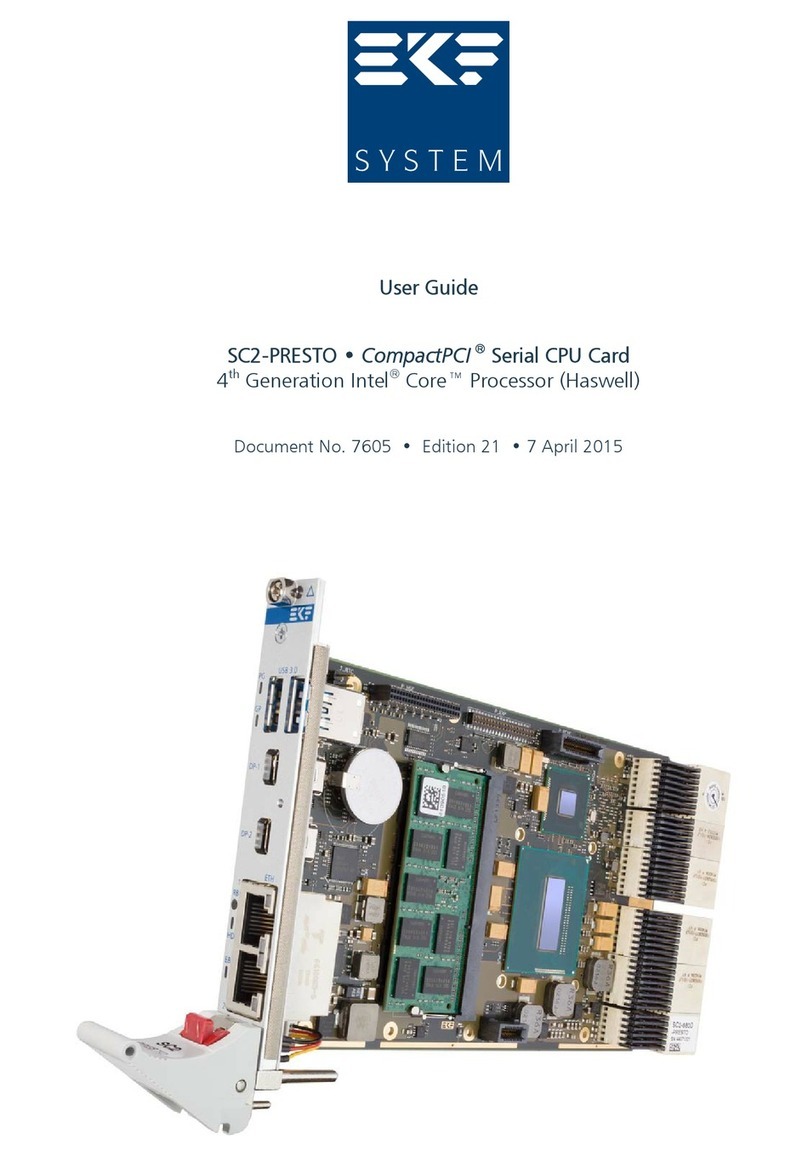
EKF SC2-PRESTO CompactPCI User manual
EKF
EKF PC1-62-GROOVE User manual
EKF
EKF SC3-LARGO User manual
EKF
EKF PCZ-NVM Manual
EKF
EKF SC4-CONCERTO User manual
EKF
EKF SC9-TOCCATA User manual

EKF
EKF PC4-PRESTO User manual
EKF
EKF C23-SATA Manual

EKF
EKF CompactPCI CCM-BOOGIE User manual
EKF
EKF PC3-ALLEGRO User manual
