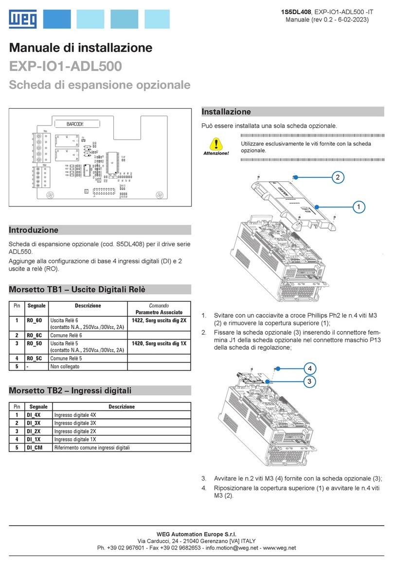
WEG EXP- SE-I1R1F2-ADV User manual

_________________________________________________________________________
EXP- SE-I1R1F2-ADV ________________________ 1
Cod. 1S9G76
Rev. 0.5 - 20-2-2023
Instruction Manual
EXP- SE-I1R1F2-ADV
Incremental Sinusoidal (SE)
Encoder expansion card S5L31
•1 1Vpp Encoder input
•1 TTL Encoder Output Repetition
•2 Channel freeze
\
Introduzione / Introduction
Questa scheda può essere utilizzata solo con drive ADV200 versione firmware 3.0 e successive
This card can be used only with drive ADV200 firmware version 3.0 and later
Introduzione / Introduction
Scheda di espansione per 1 ingresso encoder sinusoidale 1 Vpp / 2 ingressi freeze / 1 uscita
TTL per i drive ADV200.
E' possibile montare fino a due schede encoder per Drive, per maggiori dettagli
vedere il capitolo 5.4 del manuale ADV200 Guida Rapida all'installazione.
Gli ingressi Freeze congelano la posizione encoder e sono utilizzati solo da MDPlc
The card adds 1 Sinusoidal 1Vpp encoder input / 2 freeze inputs / 1 TTL output to the
ADV200 drive.
It’s possible to mount up to 2 encoder cards for each drive; for more details see chapter 5.4
of ADV200 Quick Start Up Guide.
The Freeze inputs store the encoder position and can be used only by MDPlc
Fissaggio / Mounting
Fare riferimento al capitolo Installazione schede opzionali del manuale
ADV200 Guida rapida all'installazione.
Refer to ADV200 Quick Start up manual, chapter Installation of optional cards.
ATTENZIONE: Utilizzare solo le viti in dotazione ! CAUTION: Use only the supplied screws !
Possono essere inserite fino a tre schede opzionali nei tre alloggiamenti (Slot) che si
trovano sotto la copertura superiore:
• Slot 1: dedicato alle schede IO (EXP-IO-...-ADV) (*)
• Slot 2: dedicato alle schede Encoder (EXP-...-ADV)
• Slot 3: dedicato alle schede Bus di campo (EXP-PDP-ADV, EXP-CAN-ADV, ecc) (*)
Up to three optional cards can be inserted in the three slots under the top cover:
• Slot 1: dedicated to IO cards (EXP-IO-...-ADV) - (*)
• Slot 2: dedicated to Encoder cards (EXP-...-ADV)
• Slot 3: dedicated to field Bus cards (EXP-PDP-ADV, EXP-CAN-ADV, etc.)(*)
(*) Nel caso sia necessario gestire 2 o 3 encoder, in questi Slot possono essere
inserite anche le schede per gli encoder digitali (EXP-DE-I1R1F2-ADV e EXP-DE-
I2R1F2-ADV), vedere il capitolo 11.5.1 del manuale ADV200 Guida rapida per
maggiori dettagli.
(*) If managing 2 or 3 encoders, these slots can also be used for the digital encoder
cards (EXP-DE-I1R1F2-ADV and EXP-DE-I2R1F2-ADV), see section 11.5.1 ADV200
Quick Start up manual, for further details.
Importante! Se viene inserita una scheda opzionale in uno Slot errato, il drive segnalerà un
messaggio di errore.
Attention! If an optional card is inserted in an incorrect Slot, the drive will send an error
message.

_________________________________________________________________________
EXP- SE-I1R1F2-ADV ________________________ 2
Connessione / Connections
Sezione dei cavi / Wire sizes: 0.2 ... 2.5 mm2 (AWG 24 ... 12)
Utilizzare cavi schermati con doppini twistati, la schermatura deve essere fissata agli
omega come indicato nel manuale del drive al capitolo 11.5.
Use shielded cables with twisted pairs. Shielding must be fixed to omega cables as
described in chapter 11.5 of the drive manual.
Morsett
o
Terminal
Designazione
Designation Funzione Function Note
S5
+VE
Alimentazione encoder programmabile
Programmable encoder power supply
(1)
C5
0VE
Riferimento alimentazione encoder
Reference encoder power supply
21
A+ IN
Canale A+ incrementale sinusoidale
Sinusoidal incremental channel A+
22
A- IN
Canale A- incrementale sinusoidale
Sinusoidal incremental channel A-
23
B+ IN
Canale B+ incrementale sinusoidale
Sinusoidal incremental channel B+
24
B- IN
Canale B- incrementale sinusoidale
Sinusoidal incremental channel B-
25
Z+ IN
Canale Z+ impulso di zero
Zero pulse Z+ channel
26
Z- IN
Canale Z- impulso di zero
Zero pulse Z- channel
31
-
Non usato
Not used
32
-
Non usato
Not used
33
-
Non usato
Not used
34
-
Non usato
Not used
51
DI CM
Comune freeze
Freeze common
52
DI F1
Freeze 1
Freeze 1
53
DI F2
Freeze 2
Freeze 2
41
A+ OUT
Ripetizione canale A+ incrementale digitale
Digital incremental channel A+ repetition
42
A- OUT
Ripetizione canale A- incrementale digitale
Digital incremental channel A- repetition
43
B+ OUT
Ripetizione canale B+ incrementale digitale
Digital incremental channel B+ repetition
44
B- OUT
Ripetizione canale B- incrementale digitale
Digital incremental channel B- repetition
(1) Tramite tastierino (menù CONFIG ENCODER, PAR 2102 Alimentaz encoder) è possibile
selezionare il valore della tensione di alimentazione interna dell’encoder con step minimo 0,1V.
(2) Considerare l’eventuale caduta di tensione dovuta alla lunghezza del cavo quando si imposta la
tensione di alimentazione.
(1) The internal power supply of the encoder can be selected from the keypad (ENCODER CONFIG
menu, PAR 2102 Encoder supply) with minimum step 0.1 V
(2) Consider the possible voltage drop due to the length of the cable when you set the supply voltage.
Encoder option type
Def
Min
Max
EXP-SE-I1R1F2-ADV
5.2 V
5.2 V
6.0 V
S5
21
22
23
24
25
26
51
52
53
41
42
43
44
XE
XER
C5

_________________________________________________________________________
EXP- SE-I1R1F2-ADV ________________________ 3
Leds
+VE S0
PWR S1
PWR
Green
Indica che l’espansione è alimentata ed attiva The led is ON when the expansion card is powered and
+VE
Green
Indica che l’encoder è alimentato
The led is ON when the encoder is powered
S0
S1
Yellow
Led di diagnostica.
Se l’encoder è cablato correttamente, questi led lampeg-
giano con sequenza binaria.
Diagnostic LEDs..
If the encoder is wired properly, these LEDs flash with a
binary sequence.

_________________________________________________________________________
EXP- SE-I1R1F2-ADV ________________________ 4
Schemi / Diagrams
Incremental Sinusoidal Encoder (SE)
Ripetizione Encoder - Repeat Encoder
(*)
Collegamento schermatura, vedere figura 5.2.3.1 del manuale ADV200 Guida. Rapida.
Connection of shielding, see figure 5.2.3.1 on ADV200 Quick Start
41
42
43
44
(*)
B- out
B+ out
A- out
A+ out
23
24
25
26
31
32
34
51
52
53
S5
C5
21
33
22
0VE out
+VE out
A+
A-
B+
Z+
B-
Z-
(*)
DI - F2
DI - F1
DI - CM

_________________________________________________________________________
EXP- SE-I1R1F2-ADV ________________________ 5
Dati tecnici / Technical data
Incrementali / Incremental
Canali / Channels
A+ A-, B+ B-, Z+ Z-, differenziali.
Gestita mancanza segnali encoder (solo
canali A+ A-, B+ B-).
A+ A-, B+ B-, differential.
Management of loss of encoder signals
(only
A+ A-, B+ B- channels).
Frequenza max. / Max frequency 200 kHz (verificare il numero di impulsi
encoder in funzione della velocità massima)
200 kHz (check the number of encoder
impulses according to the maximum speed)
Numero di impulsi / Number of impulses
min 128, max 32768 (default 1024)
Interfaccia elettrica / Electrical interface
Channels A/B 0,8V ≤Vpp ≥1,2V (typ. 1,0V) −Channel Z 0,2V ≤Vpp ≥0,8V
Capacità di carico / Load capacity
8mA @ 1.0Vpp (Zin 120Ω)
Alimentazione / Power supply
min +5,2V, max +6,0V (default + 5,2V)
− Imax 150mA . Alimentazione interna
programmabile (1)
min +5.2 V, max +6.0 V (default + 5.2 V) −
Imax 150 mA.
Programmable internal power supply (1)
Lunghezza cavo / Cable length
50mt max
Ripetizione Encoder -Repeat Encoder -RE (TTL line-driver)
Le schede di espansione Encoder dispongono di un’uscita dell’encoder incrementale con livelli del Driver Linea TTL da utilizzarsi come
ripetizione del dispositivo di retroazione del servomotore. Questa funzione viene eseguita via hw ed è possibile ripetere un’uscita
encoder con un divisore programmabile. I segnali d’uscita dell’encoder sono disponibili sul connettore XER.
Encoder expansion cards have an incremental encoder output with TTL Line Driver levels to be used to repeat the servomotor
feedback device. This function is performed via HW and an encoder output can be repeated with a programmable divider. The
encoder output signals are available on the XER connector:
Canali / Channels
A+ A-, B+ B-, differenziali line driver.
A+ A-, B+ B-, differential line drivers.
Frequenza max. / Max frequency
200 kHz
Numero di impulsi / Number of impulses
ripetizione 1/1-1/2-1/4-1/8 (default 1/1)
1/1-1/2-1/4-1/8 repeat (default 1/1)
Interfaccia elettrica / Electrical interface
TTL (ref. GND) Ulow ≤ 0.5V Uhigh ≥ 2.5V
Capacità di carico / Load capacity
20mA @ 5,5V (Zin 120Ω)
Alimentazione / Power supply
5,2V
Lunghezza cavo / Cable length
50mt max

_________________________________________________________________________
EXP- SE-I1R1F2-ADV ________________________ 6
Riconoscimento della scheda opzionale / Optional card recognization
1 - All’accensione il drive riconosce la presenza della scheda opzionale nello slot di
espansione, sul display per alcuni secondi viene visualizzato questo messaggio.
1 - At power-on, the drive recognizes the presence of optional card in the expansion slot,
this message is shown on the display.
2- Nel menu 02 INFORMAZIONI DRIVE, selezionare il parametro PAR 532 Tipo scheda
slot 2 (oppure PAR 530 Tipo scheda slot 1, PAR 534 Tipo scheda slot
3) per leggere il tipo di scheda riconosciuta.
2- On 02 DRIVE INFO menu, select the PAR 532 Slot 2 card type (or PAR 530
Slot 1 card type, PAR 534 Slot 3 card type) to read the recognized card type.
Descrizione / Description
Tipo scheda / Card type
0 Nessuna / None
-
1544
Enc 1
EXP-DE-I1R1F2-ADV
2056
Enc 7
EXP-DE-I2R1F2-ADV
1800
Enc 2
EXP-SE-I1R1F2-ADV
520
Enc 3
EXP-SESC-I1R1F2-ADV
776
Enc 4
EXP-EN/SSI-I1R1F2-ADV
1032
Enc 5
EXP-HIP-I1R1F2-ADV
255
Sconosciuta / Unknown
-
WEG Automation Europe S.r.l.
Via Carducci, 24 - 21040 Gerenzano [VA] ITALY
T+
T-
EN
LOC
ILim
n=0
AL
Option detect slot 2
MESSAGE
Code: 0008H-8
01
T+
T-
EN
LOC
ILim
n=0
AL
01 MONITOR
03 STARTUP WIZARD
02 DRIVE INFO
04 DRIVE CONFIG
T+
T-
EN
LOC
ILim
n=0
AL
Slot 2 card type
02.16
Enc 2
532
PAR :
Value 1800
1
2
Table of contents
Other WEG Computer Hardware manuals