EKF C42-SATA Manual
Technical Information
C42-SATA
Micro SATA SSD
Solid State Drive Mezzanine Module
Document No. 5290 • Ed. 11 • 17 April 2013

Technical Information C42-SATA • Low Profile Micro SATA SSD Mezzanine Module
Contents
AboutthisManual ........................................................... 3
EditionHistory......................................................... 3
RelatedDocuments ..................................................... 4
Nomenclature ......................................................... 4
TradeMarks .......................................................... 4
Legal Disclaimer - Liability Exclusion ......................................... 4
Standards ............................................................ 4
Features................................................................... 6
ShortDescription....................................................... 7
BlockDiagram......................................................... 9
ComponentAssembly .................................................. 10
InstallingandReplacingComponents............................................ 12
BeforeYouBegin...................................................... 12
Warnings ...................................................... 12
Caution ....................................................... 12
InstallingtheBoardAssembly ............................................ 13
RemovingtheBoardAssembly............................................ 14
EMCRecommendations................................................. 15
Technical Reference - Connectors ............................................... 16
Caution............................................................. 16
P-SATA1(MicroSATAReceptacle) ......................................... 17
P-MEZ .............................................................. 18
Schematics................................................................ 20
© EKF -2- ekf.com

Technical Information C42-SATA • Low Profile Micro SATA SSD Mezzanine Module
About this Manual
This manual is a short form description of the technical aspects of the C42-SATA, required for
installation and system integration. It is intended for the advanced user only.
Edition History
EKF Document Ed. Contents/Changes Author Date
Text # 5290
c42_tie.wpd
1 Technical Information C42-SATA
English, Preliminary Edition
jj 14 October 2008
2 Review jj 4 December 2008
3 Review jj 10 February 2009
4 Added Photos MicroSATA SSD Intel and other Brands jj 2 March 2009
5 General review jj 16 April 2009
6 C42-SATA illustrations updated jj 18 May 2009
7 Added sectional drawing jj 5 June 2009
8 Added photos jj 5 March 2010
9 Added photos jj 26 May 2010
10 Added photos jj 29 March 2012
11 Added photos showing C42-SATA on PCS-BALLET jj 17 April 2013
© EKF -3- ekf.com

Technical Information C42-SATA • Low Profile Micro SATA SSD Mezzanine Module
Related Documents
Related Documents CPU Cards
CCM-BOOGIE www.ekf.com/c/ccpu/ccm/ccm_e.html
PC1-GROOVE www.ekf.com/p/pc1/pc1.html
PC2-LIMBO www.ekf.com/p/pc2/pc2.html
SC1-ALLEGRO www.ekf.com/s/sc1/sc1.html
Related Documents Mezzanine Modules and Side Cards
C40 ... C47 Series
Mezzanine Storage Modules
www.ekf.com/c/ccpu/c4x_mezz_ovw.pdf
Mezzanine Modules Overview www.ekf.com/c/ccpu/mezz_ovw.pdf
The EKF Mezzanine Module Concept www.ekf.com/c/ccpu/cpci_mezzanine_evolution.pdf
Nomenclature
Signal names used herein with an attached '#' designate active low lines.
Trade Marks
Some terms used herein are property of their respective owners, e.g.
<Intel, Pentium, Celeron, Core 2 Duo, Core i7: ® Intel
<CompactPCI ®: ® PICMG, CompactPCI ® Serial : ® PICMG
<Windows XP, WEPOS/POSready, Windows 7, Windows 8: ® Microsoft
<EKF, ekf system: ® EKF
EKF does not claim this list to be complete.
Legal Disclaimer - Liability Exclusion
This document has been edited as carefully as possible. We apologize for any potential mistake.
Information provided herein is designated exclusively to the proficient user (system integrator,
engineer). EKF can accept no responsibility for any damage caused by the use of this manual.
Standards
Specifications/Standards
Micro SATA SFF-8144 Specification (ftp://ftp.seagate.com/sff)
SATA Serial ATA 2.5/2.6 Specification (www.sata-io.org)
© EKF -4- ekf.com

Technical Information C42-SATA • Low Profile Micro SATA SSD Mezzanine Module
C42-SATA & SC1-ALLEGRO CPU Card
C42-SATA & SC1-ALLEGRO CPU Card Assembly
© EKF -5- ekf.com

Technical Information C42-SATA • Low Profile Micro SATA SSD Mezzanine Module
Features
Feature Summary
Form Factor <Proprietary size mezzanine module 66mm x 97.5mm x 1mm
<Fits into the 4HP (20.3mm) envelope of the CPU carrier board
<Typically delivered as a ready to use assembly unit (including the
CCM-BOOGIE or successor CPU card)
<Mounting position right (on top of the CPU board)
Host I/F Connector
(Bottom Mount to
CPU Carrier)
<High speed mezzanine connector suitable for PC1-GROOVE,
SC1-ALLEGRO and successor CPU carrier boards
<Up to 4 x SATA channels (SATA2 - SATA4 channels not in use on the
C42-SATA)
<Up to 4 x USB ports (not in use on the C42-SATA)
SATA Usage <SATA1 (typically from the PCH southbridge on a CPU carrier board),
bound to the C42-SATA on-board Micro SATA solid state drive
(SSD), 1.8-inch size
<SATA2 - SATA4 channels not in use on the C42-SATA
Solid State Drive <Module suitable for 1.8-inch Micro SATA SSD (alternatively hard disk
drive), dimensions according to SFF-8144 (54mm x 78.5mm x
5mm)
<All major operating systems supported (boot device)
<Variety of industrial grade Micro SATA SSD manufacturers, e.g. Intel,
Micron, Toshiba, Samsung, SLC or MLC available
<Up to 800GB capacity as of current (Intel® Solid-State Drive DC
S3500 Series)
<SSD can be provided by EKF or by customer
Top Mount
Connectors
<P-SATA1 for on-board Micro SATA drive
<7 pins signal section + 9 pins power section integrated docking
connector
Thermal
Conditions
Environmental
Conditions
<Operating temperature: 0°C ... +70°C
<Storage temperature: -40°C ... +85°C, max. gradient 5°C/min
<Humidity 5% ... 95% RH non condensing
<Altitude -300m ... +3000m
<Shock 15g 0.33ms, 6g 6ms
<Vibration 1g 5-2000Hz
EC Regulations <EN55022, EN55024, EN60950-1 (UL60950-1/IEC60950-1)
<2002/95/EC (RoHS)
MTBF tbd
© EKF -6- ekf.com

Technical Information C42-SATA • Low Profile Micro SATA SSD Mezzanine Module
Short Description
Available as a mezzanine add-on expansion
board to EKF CPU carrier cards, the C42-SATA
accommodates a Solid State Drive (SSD), as a
rugged and fast mass storage media. The
C42-SATA has been designed to fit into the 4HP
(20.32mm) envelope of a CPCI CPU carrier
board, so that another 4HP pitch mezzanine
expansion board can be stacked above the
CPU/C42 assembly in addition.
As of current, Micro SATA solid state drives are
available with up to 800GB capacity as of
current, delivering sufficient space for
installation of any popular operating system.
The 1.8-inch Micro SATA SSD will be fastened
by means of a screw locked retainer, for
optimum reliability. A Flash technology based
SATA drive provides significant advantages
compared to rotating memory solutions (aka
hard disk), e.g. less power consumption, faster
data I/O transfers, lower latency time, industrial
temperature grade and superior immunity
against shock and vibration.
SSDs of different vendors may differ
significantly in read/write access times. Contact
EKF for choosing an optimum solution.
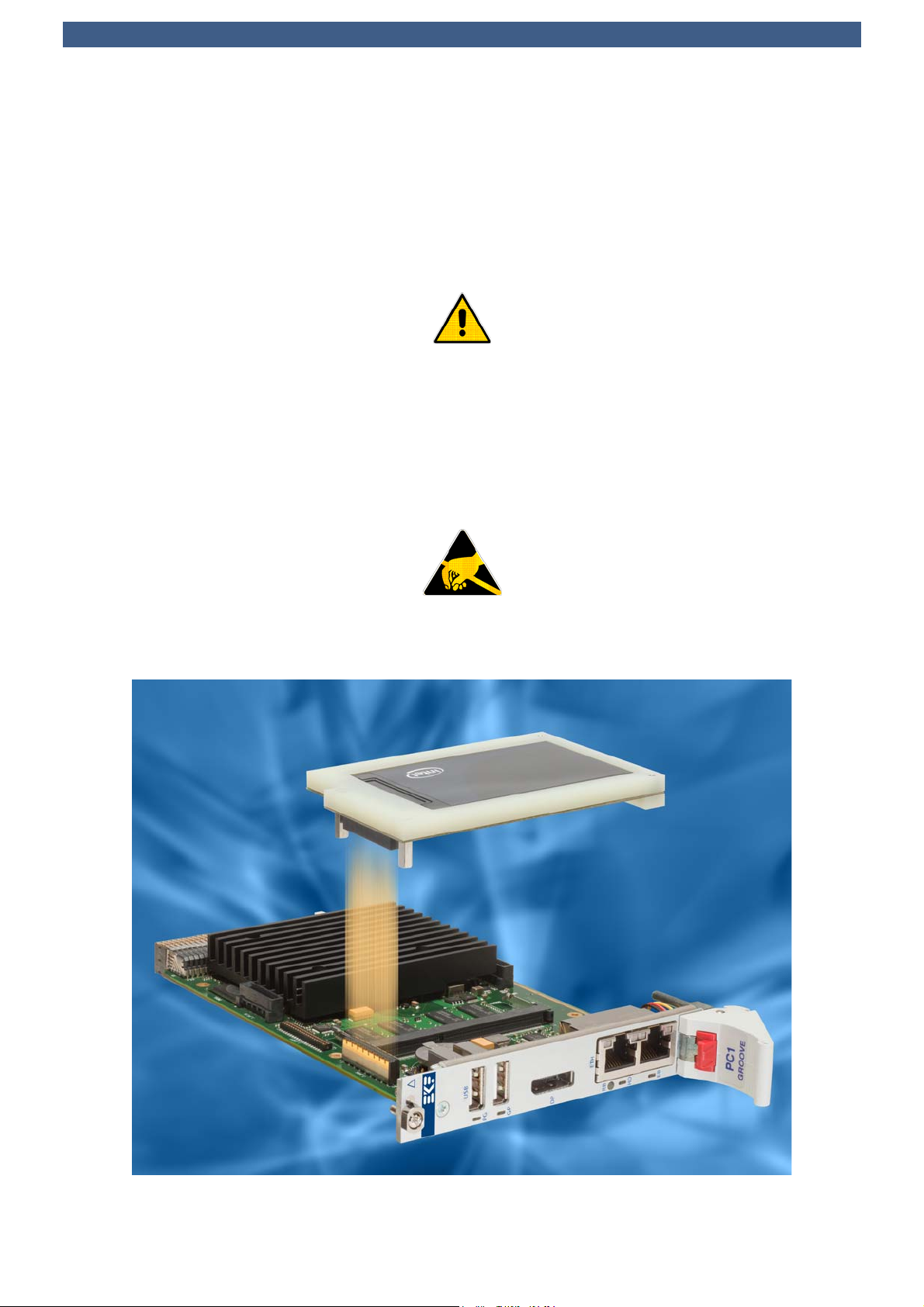
C42-SATA and PC1-GROOVE CPU Card Assembly
© EKF -7- ekf.com

Technical Information C42-SATA • Low Profile Micro SATA SSD Mezzanine Module
Intel® MicroSATA SSD
C42-SATA (w/o Drive)
© EKF -8- ekf.com

Technical Information C42-SATA • Low Profile Micro SATA SSD Mezzanine Module
Block Diagram
High Speed
Mezzanine
Connector
Micro SATA
Receptacle
P-MEZ
SATA1
Simplified Block Diagram
C42-SATA
1.8-Inch
SATA
SSD
Solid State Drive
© EKF -9- ekf.com
Technical Information C42-SATA • Low Profile Micro SATA SSD Mezzanine Module
Component Assembly
1.8-Inch
SATA
Solid State Drive
© EKF
EKF Part No. 710.9.HDD_18.2 • Drawing No. 4459
C42-SATA
Mounting Shell
PCI Express x 4
C42-SATA
Mezzanine
Option
SDVO-2
CPU
Carrier
Board
draft only - do not scale • © EKF • ekf.com
LPC/USB/AUDIO
1.8-Inch
SATA
Solid State Drive
© EKF
EKF Part No. 710.9.HDD_18.2 • Drawing No. 4459
C42-SATA
Mounting Shell
© EKF -10- ekf.com
Technical Information C42-SATA • Low Profile Micro SATA SSD Mezzanine Module
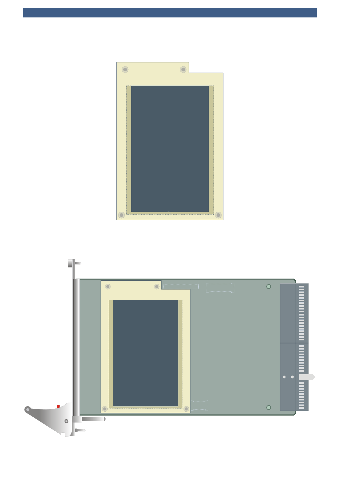
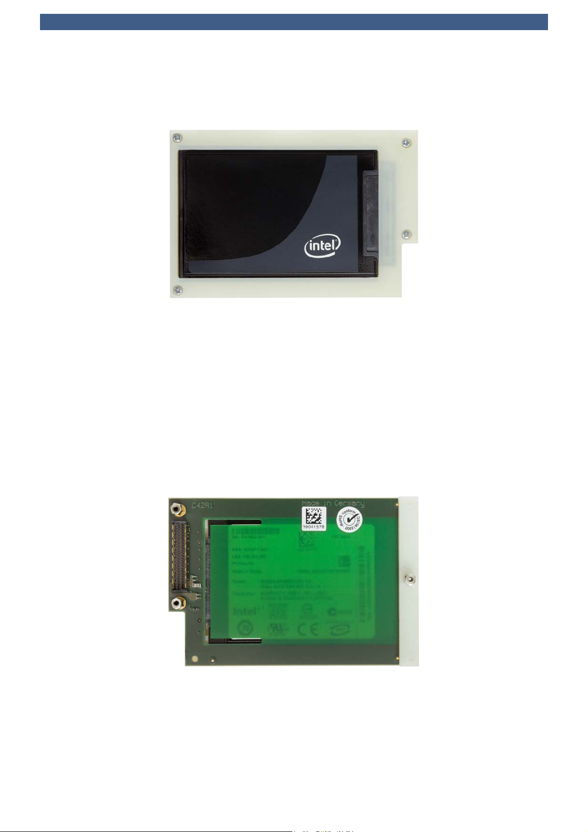
C42-SATA Top View
C42-SATA Bottom View
© EKF -11- ekf.com
Technical Information C42-SATA • Low Profile Micro SATA SSD Mezzanine Module
C42-SATA over the PC1-GROOVE CPU Carier Card
Installing and Replacing Components
Before You Begin
Warnings
The procedures in this chapter assume familiarity with the general terminology associated with
industrial electronics and with safety practices and regulatory compliance required for using and
modifying electronic equipment. Disconnect the system from its power source and from
any telecommunication links, networks or modems before performing any of the
procedures described in this chapter. Failure to disconnect power, or telecommunication
links before you open the system or perform any procedures can result in personal injury
or equipment damage. Some parts of the system can continue to operate even though
the power switch is in its off state.
Caution
Electrostatic discharge (ESD) can damage components. Perform the procedures described in this
chapter only at an ESD workstation. If such a station is not available, you can provide
some ESD protection by wearing an antistatic wrist strap and attaching it to a
metal part of the system chassis or board front panel. Store the board only in its
original ESD protected packaging. Retain the original packaging (antistatic bag and
antistatic box) in case of returning the board to EKF for repair.
© EKF -12- ekf.com
Technical Information C42-SATA • Low Profile Micro SATA SSD Mezzanine Module
Installing the Board Assembly
Warning
This procedure should be done only by qualified technical personnel. Disconnect the system from its
power source before doing the procedures described here. Failure to disconnect power, or
telecommunication links before you open the system or perform any procedures can result in personal
injury or equipment damage.
Typically you will perform the following steps:
CSwitch off the system, remove the AC power cord
CAttach your antistatic wrist strap to a metallic part of the system
CRemove the board packaging, be sure to touch the board only at the front panel
CIdentify the related CompactPCI slot (peripheral slot for I/O boards, system slot for CPU boards,
with the system slot typically most right or most left to the backplane)
CInsert card carefully (be sure not to damage components mounted on the bottom side of the
board by scratching neighboured front panels)
CA card with onboard connectors requires attachment of associated cabling now
CLock the ejector lever, fix screws at the front panel (top/bottom)
CRetain original packaging in case of return
© EKF -13- ekf.com

Technical Information C42-SATA • Low Profile Micro SATA SSD Mezzanine Module
Removing the Board Assembly
Warning
This procedure should be done only by qualified technical personnel. Disconnect the system from its
power source before doing the procedures described here. Failure to disconnect power, or
telecommunication links before you open the system or perform any procedures can result in personal
injury or equipment damage.
Typically you will perform the following steps:
CSwitch off the system, remove the AC power cord
CAttach your antistatic wrist strap to a metallic part of the system
CIdentify the board, be sure to touch the board only at the front panel
Cunfasten both front panel screws (top/bottom), unlock the ejector lever
CRemove any onboard cabling assembly
CActivate the ejector lever
CRemove the card carefully (be sure not to damage components mounted on the bottom side
of the board by scratching neighboured front panels)
CStore board in the original packaging, do not touch any components, hold the board at the
front panel only
Warning
Do not expose the card to fire. Battery cells and other components could explode
and cause personal injury.
© EKF -14- ekf.com

Technical Information C42-SATA • Low Profile Micro SATA SSD Mezzanine Module
EMC Recommendations
In order to comply with the CE regulations for EMC, it is mandatory to observe the following rules:
CThe chassis or rack including other boards in use must comply entirely with CE
CClose all board slots not in use with a blind front panel
CFront panels must be fastened by built-in screws
CCover any unused front panel mounted connector with a shielding cap
CExternal communications cable assemblies must be shielded (shield connected only at one end
of the cable)
CUse ferrite beads for cabling wherever appropriate
CSome connectors may require additional isolating parts
Reccomended Accessories
Blind CPCI Front
Panels
EKF Elektronik Widths currently available
(1HP=5.08mm):
with handle 4HP/8HP
without handle
2HP/4HP/8HP/10HP/12HP
Ferrit Bead Filters ARP Datacom,
63115 Dietzenbach
Ordering No.
102 820 (cable diameter 6.5mm)
102 821 (cable diameter 10.0mm)
102 822 (cable diameter 13.0mm)
Metal Shielding
Caps
Conec-Polytronic,
59557 Lippstadt
Ordering No.
CDFA 09 165 X 13129 X (DB9)
CDSFA 15 165 X 12979 X (DB15)
CDSFA 25 165 X 12989 X (DB25)
© EKF -15- ekf.com
Technical Information C42-SATA • Low Profile Micro SATA SSD Mezzanine Module
Technical Reference - Connectors
Caution
Some of the connectors may provide operating voltage (e.g. +12V, +5V and +3.3V) to devices inside
the system chassis, such as internal peripherals. Not all of these connectors are overcurrent protected.
Do not use these connectors for powering devices external to the computer chassis. A fault in the load
presented by the external devices could cause damage to the board, the interconnecting cable and
the external devices themselves.
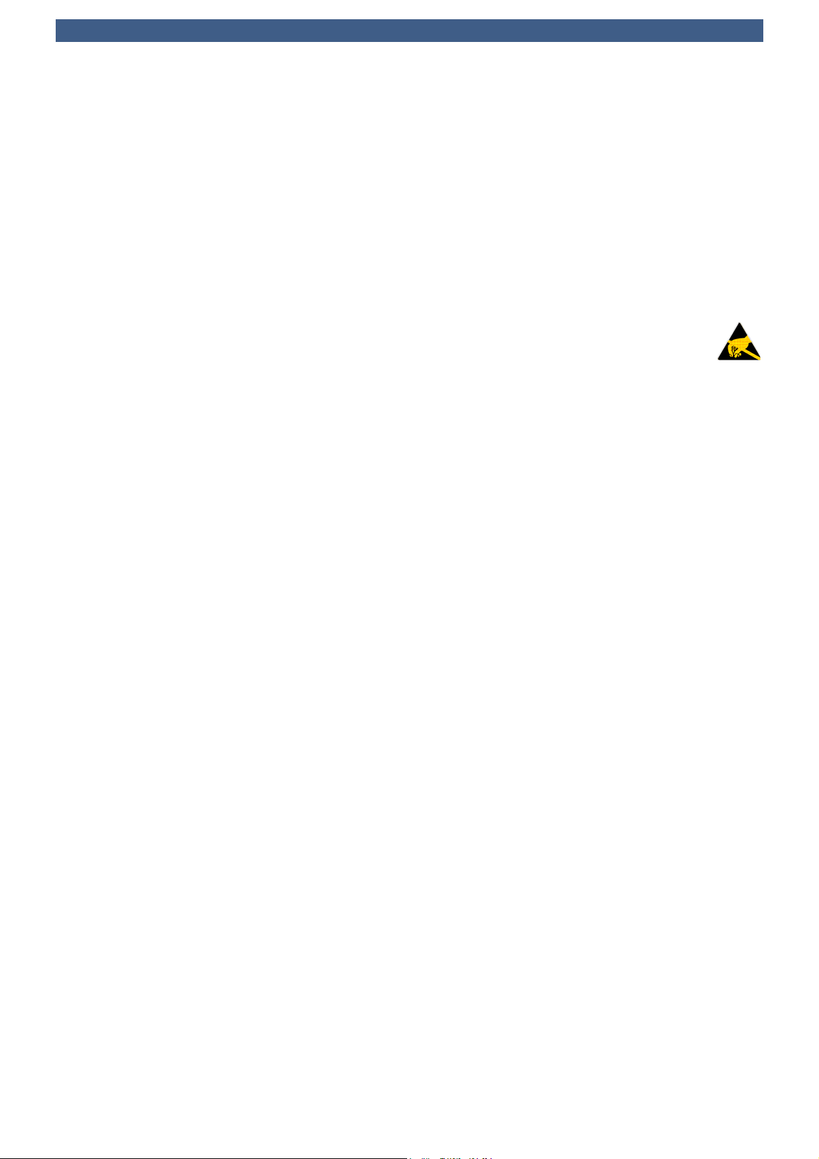
P-MEZ Sectional Drawing (North View)
Carrier Board PCB
9.0mm
C42
Side Board 4HP Pitch
P-SATA
SSD
# 710.9.HDD_18.2
S
B
B=Bolt #442.2.0109.0 M2 Inner Thread 9mm WS4
B
S
S=Screw #440.08.020.006 M2x6 DIN 7985
5.0mm
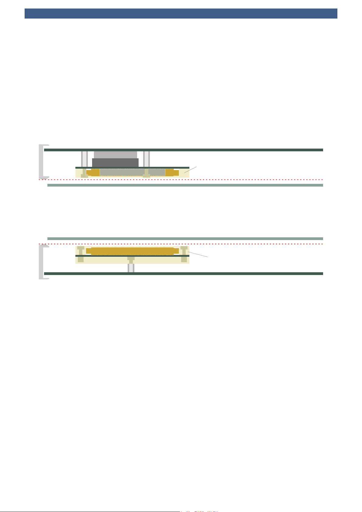
Sectional Drawing (South View)
Carrier Board PCB
# 710.9.HDD_18.A # 710.9.HDD_18.2
C42
Side Board 4HP Pitch
SSD
N
S
N
S
S
S=Screw N=Nut B=Bolt B
N=Nut #440.42.020.003 M2 Threaded Insert l=3.1mm d=3.7mm
S=Screw #440.08.020.006 M2x6 DIN 7985
B=Bolt #442.2.0105.0 M2 Inner Thread 5mm WS4
© EKF -16- ekf.com

Technical Information C42-SATA • Low Profile Micro SATA SSD Mezzanine Module
P-SATA1 (Micro SATA Receptacle)
The C42-SATA can accommodate any 1.8-inch SATA standard form factor drive according to the
SFF-8144 specification, which results in a 5.0 mm maximum height, and 78.5mm x 54.0mm
dimensions. The Micro SATA connector in use is defined in Serial ATA Rev. 2.6. Devices with 8.0mm
height (probably only hard disk) could be used on the C42-SATA, but require additional headroom
(4HP envelope for the assembly not maintained in this case).
A mounting frame is used to hold the drive in its position, for extremely rugged applications.
P-SATA1 • Micro SATA Docking Connector 7+9 • 256.016.10.01
S1 GND
S2 TX+ SATA1
S3 TX- SATA1
S4 GND
S5 RX- SATA1
S6 RX+ SATA1
S7 GND
P1 +3.3V
P2 +3.3V
P3 GND
P4 GND
P5 +5V
P6 +5V
P7 DAS (R to GND)
P8 NC
P9 NC
Signal designations RX/TX assigned with respect to the SATA host controller (ICH Southbridge). Typical
Micro SATA SSD devices are powered from a single +3.3V rail. Power is supplied (and switched on/off
according to Sx state) from the CPU carrier board, across the C42-SATA mezzanine connector P-MEZ.
Note: Do not confuse the Micro SATA connector specified by Serial ATA Rev. 2.6 with the proprietary
'Special SATA' connector as defined by Samsung (refer to Samsung 1.8” Form Factor Proposal).
Part No. 256.016.10.01 • Micro SATA Receptacle • © EKF • ekf.com
© EKF -17- ekf.com

Technical Information C42-SATA • Low Profile Micro SATA SSD Mezzanine Module
P-MEZ
The C42-SATA is equipped with a high speed mezzanine connector P-MEZ, mating with the
CCM-BOOGIE CPU carrier board and its successors. The inter-board connector is situated at the
bottom of the C42-SATA and establishes the data path and power link to the carrier board CPU. Since
the C42-SATA comes typically mounted as a unit together with the CCM-BOOGIE, there is normally no
need for the user to get access to the inter-board connector. It is described here as a reference only
and for better understanding of the C42-SATA.
The connector P-MEZ is a 1mm height shielded male pin header. Its counterpart on the CPU carrier
board is a 8mm height receptacle, for a nominal headroom of 9mm between the boards.
P-MEZ SATA & USB Mezzanine Interface
1.00mm Pitch Male Connector 1mm Height (275.90.01.068.51)
GND b1 a1 GND
SATA3_TXP b2 a2 SATA1_TXP
SATA3_TXN b3 a3 SATA1_TXN
GND b4 a4 GND
SATA3_RXN b5 a5 SATA1_RXN
SATA3_RXP b6 a6 SATA1_RXP
GND b7 a7 GND
SATA4_TXP b8 a8 SATA2_TXP
SATA4_TXN b9 a9 SATA2_TXN
GND b10 a10 GND
SATA4_RXN b11 a11 SATA2_RXN
SATA4_RXP b12 a12 SATA2_RXP
GND b13 a13 GND
USB3_P b14 a14 USB1_P
USB3_N b15 a15 USB1_N
GND b16 a16 GND
USB4_P b17 a17 USB2_P
USB4_N b18 a18 USB2_N
GND b19 a19 GND
USB3_OC# b20 a20 USB1_OC#
USB4_OC# b21 a21 USB2_OC#
+5VS 2) b22 a22 +3.3VS 1)
+5VS 2) b23 a23 +3.3VS 1)
+5V b24 a24 +3.3V
RSVD b25 a25 +12V
1) 2) Switched voltages from carrier board, according to CPU sleep state S0
Notes:
<All s# connector pins (shield) are tied to GND
<All TX/RX designations with respect to SATA controller (TX controller = RX drive, RX controller = TX drive)
a1
s1
s9s18
s10
a25
b25
b1
1.00
m
m
Pitch High Speed
M
ale Connector
© EKF 275.90.01.068.51 ekf.com
© EKF -18- ekf.com

Technical Information C42-SATA • Low Profile Micro SATA SSD Mezzanine Module
C42-SATA on the PCS-BALLET Side Card
© EKF -19- ekf.com

Technical Information C42-SATA • Low Profile Micro SATA SSD Mezzanine Module
Schematics
Complete circuit diagrams for this product are available for customers on request. Signing of a non-
EKF reserves the right to refuse distribution of confidential information material for any reason that
EKF may consider substantial.
C42-SATA as an Option on the SP2-LUTE Wireless Card
© EKF -20- ekf.com
Table of contents
Popular Storage manuals by other brands

Checkpoint
Checkpoint Smart-1 225 Installing and Removing

Z.I.P.P.ER MASCHINEN
Z.I.P.P.ER MASCHINEN ZI-GAB100AN user manual

Elite
Elite ELITEPOB-300SLIM-0215 quick guide

Sun Microsystems
Sun Microsystems StorEdge 3900 Series troubleshooting guide

Asgard
Asgard ACCESS E PLUS Assembly instructions

Drobo
Drobo B800i How-to guide


