Ekolot KR-030 TOPAZ Installation instructions

Manufacturer: PPHU
EKOLOT
Type: KR-030TOPAZ
Handling, maintenanceand periodicinspections
manual
Issue: 1
Rev. No: Date:July2010
Date: Page
1
HANDLING, MAINTENANCE ANDPERIODIC
INSPECTIONS MANUAL
AIRCRAFT
KR-030 TOPAZ
SERIALNUMBER:30 -..…. -…...
Manufacturer: PPHU
EKOLOT
Type: KR-030TOPAZ
Handling, Maintenanceand PeriodicInspections
Manual
Issue: 1
Rev. No: Date:July2010
Date: Page
2
CONTENTS
PAGE
1
SMALL REPAIRS 2
2
PREPARATIONOFTHEAIRCRAFTFORLONG-TERM
SUSPENSIONOFOPERATION 4
3
WORKS TO BE DONEAFTERTHELONG-TERM
SUSPENSIONOFOPERATION 5
4
ROUTINEMAINTENANCELIST 5
5
PERIODICALINSPECTIONSCHEDULE 6
6
LIFECYCLEOFASSEMBLIES 6
7
ASSEMBLYAND DISASSEMBLYOFTHEAIRCRAFT 7
8
ADJUSTMENTPOINTSOFTHECONTROLSYSTEM 12
9.1
FRONTUNDERCARRIAGE 15
9.2
MAINUNDERCARRIAGE 24
9.3
CONTROLSYSTEMS 33
9.3.1
RUDDERCONTROLSYSTEM 33
9.3.2
ELEVATORAND AILERONSCONTROLSYSTEM 47
9.3.3
FLAPS DRIVE SYSTEM 57
9.4
POWERPLANT62
9.4.1
ENGINEMOUNTINGSYSTEM 62
9.4.2
ENGINECONTROLSYSTEM 87
9.4.3
FUELSYSTEM 95
9.4.4
ENGINELUBRICATIONSYSTEM 118
9.4.5
ENGINECOOLING SYSTEM 127
9.5
AIRFRAMESTRUCTURE 145
9.5.1
DOORS 145
9.5.2
REPLACEMENTOFGLAZING 153

Manufacturer: PPHU
EKOLOT
Type: KR-030TOPAZ
Handling, Maintenanceand PeriodicInspections
Manual
Issue: 1
Rev. No: Date:July2010
Date: Page
3
1. SMALLREPAIRS
NOTICE:Incaseofanydamagetothepropeller, please readthe
instructionsplacedintheOperationManualforASType
Propellers.
NOTICE:
All damagestothefuselagecomposite structureandmethodsofrepair
mustbeconsultedwiththeaircraftmanufacturer.
a)Small cracksand paintingimperfectionsaretoberemovedbymeansof
apaintbrush.
b)Cracksinthewindshieldandsidewindowscan be stoppedfrom
spreading bydrillinga ≈∅2holeattheendofcrack.
c)Duringthepainting workson controlsurfaces,suchasflaps,ailerons,
rudderor elevator,thecomponentmustbeweighedwiththeoriginal
factorycoating.Afterremoving the oldcoating and applying anew
coating,thecomponentshouldnot beheavierthanbefore therepair.
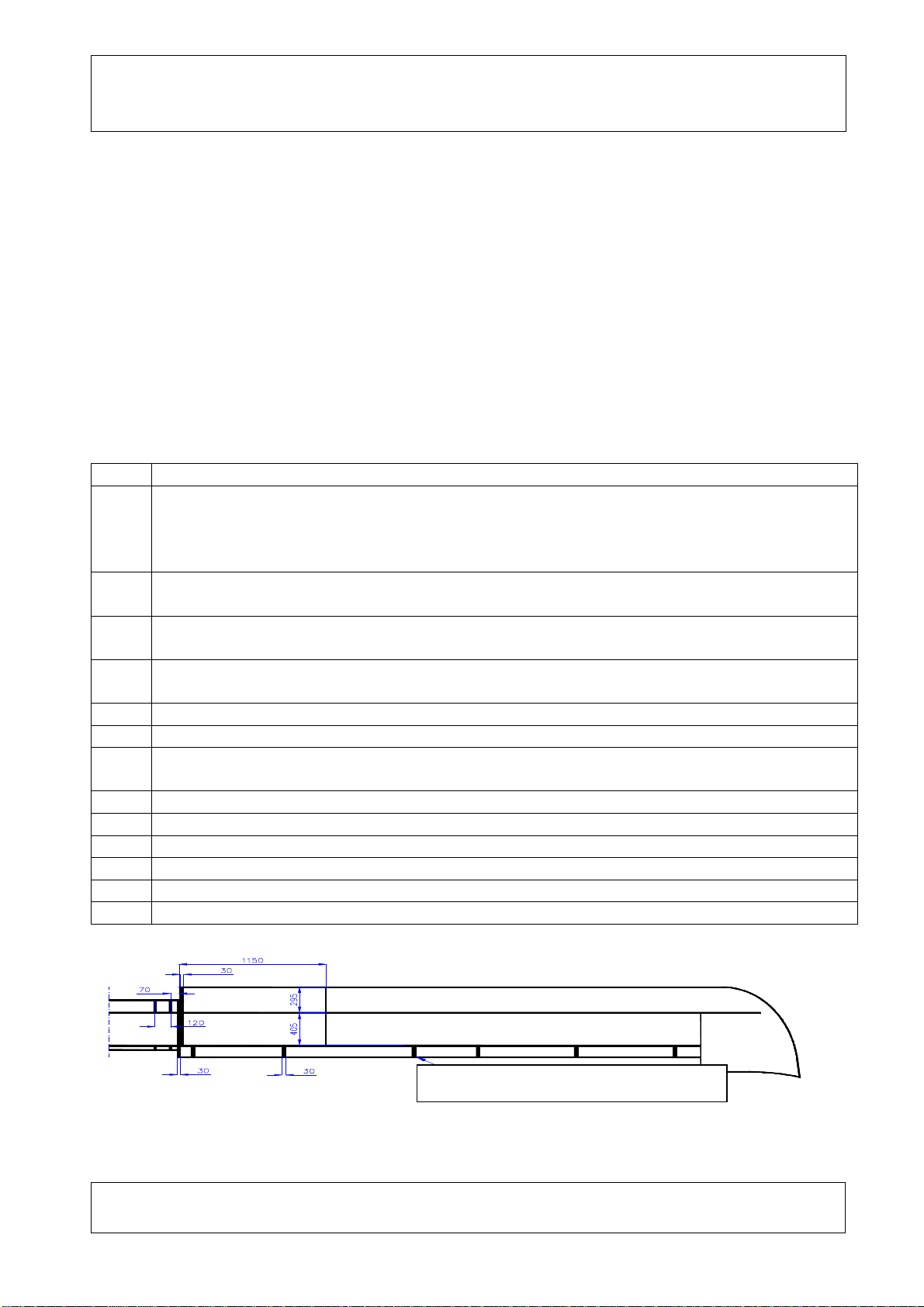
After repainting,ailerons' centre ofgravitymustbe verified inthe
following way:
Aileronistobe fixedwithtwohinges(number1and3,counting along
the span)inupside downposition.Thesuspendedaileron mustbe free
toswing.
Ifthe aileronnosehasatendencytogo downor theaileronstaysin
horizontalposition itcanbepresumedthat itiscorrectlybalanced.
Iftheaileron nosehasatendencytogoup,ameasurement mustbe
performedasper thefollowingdrawing.
P
zawieszenie
Aileronbalancemeasurement diagram
SUSPENSION POINT
Manufacturer: PPHU
EKOLOT
Type: KR-030TOPAZ
Handling, Maintenanceand PeriodicInspections
Manual
Issue: 1
Rev. No: Date:July2010
Date: Page
4
Value of the P forcerequiredtomaintainhorizontalpositionof the
aileron must notbe greater than0,02kG.
Force Pmust beapplied inthe symmetryplaneofoneof the fastening
point. Toeliminateinfluenceof friction during measurementof Pforce,
the measurement mustbeexecutedbydeflectingthe aileron’send up
anddownandthen arithmeticmean for calculationmustbeapplied.
d)When removingtheoldcoating,specialconsideration must begivento
avoiddestructionof the compositestructure(see: point a)
2.PREPARATIONOFTHEAIRCRAFTFORLONG-TERMSUSPENSION
OFOPERATION
-Disconnect and removethe battery.
-Securetheengine according tothe engine OperationandMaintenance
Manual.
-Emptyfueltanksthrough thefuselage bellydrainvalve.Setthe CUT-
OFFvalvetoOPENposition.
-Dismantlethe aircraft (see:point8.9).Placethe wingsand control
surfaceson specialprops,ideallyinverticalposition,aileron and
controlsurfacestothetop.
-Attachmentpoints,pinsand boltsare tobe cleaned withnaphtha and
coveredwithVaselineorthickgrease.
-Coverthecomponentswithprotectivecovers.
-Fuselageistobeproppedinsuchawaythe tiresdonothavecontact
withthe ground.
-Attachmentpoints,controlsystem,pinsand boltsaretobe covered
withVaselineand wrapped ingreasedclothes.
-Letairoutoftiresto0,5Bar.
-Rearpartof the fuselage (thetail seat)istobe properlycovered.
-Boltsfor mountingwingsare tobecovered withathinlayerof
Vaseline,andthenputintoaplasticbagwithnutsandwashers,which
isinturntobeplacedintheluggage compartment.
-Mountingboltsseatsinwingsand fuselage are tobe cleaned,covered
withathinlayerof Vaselineand pluggedwithpiecesof clothsoaked in
grease.
-Closeandsecurethe door.
-Put aprotectivecover on all elements.
3.WORKSTO BEDONEAFTERTEMPORARYSUSPENSIONOF
OPERATION
Manufacturer: PPHU
EKOLOT
Type: KR-030TOPAZ
Handling, Maintenanceand PeriodicInspections
Manual
Issue: 1
Rev. No: Date:July2010
Date: Page
5
-All partspreserved withgreaseare tobewashedand cleaned.
-Put airintirestothelevelof 1,8-2,0Bar.
-Carryout activities1, 2,3,4,5,6, intheprocedure 8.6.
-Installandconnectthebattery(“+"terminaltothe"+"cableand"-"
terminaltothe"-"cable).
-Removeall preservationfrompowerplant, accordingtothepowerplant
manual.
-Carryout activities7,8,9, intheprocedure8.6.
-Assembletheaircraft (see: point8.9).
-Carryout activities10,11,12, intheprocedure8.6.
4.ROUTINEMAINTENANCELIST
Pos.
Inspection/ check
1
Inspection of airframestructure, givingspecialconsideration toallelementsthat are
heavilyloaded duringtake-off andlanding. Controlof qualityof glue connection of
the wing shellwithinternalwing structurebymeansof tapping, according tothe
schemeattached.
2
Inspection ofallmetaljointspinsand bolts.Check forclearancesinallcriticaljoints
of the airframe.
3
Inspection ofallsafetyelementsinparticularelementsofairframe,powerplantand
controlsystem.
4
Check offrictionincontrolsystem,controlsystemfair-leadscheck.Flapsand
aileronscheck: externalsurfaces, hinges, drivesystemelements. .
5
Inspection and check of undercarriage.
6
Inspection and check ofinstruments. Checkingairtightness of pneumaticsystems.
7
Inspection and checkoffueland oilsystems(band clipson pipes).Allcracked or
scratched fuelpipesmust be replaced.
8
Inspection of wiring system, check securityofcableconnections.
9
Inspection of externalmetalsurfacesandprotectivecoatings.
10
Inspection and check of brakesystem.
11
Inspection of controlsurfacesdisplacement.
12
Inspection and check of propelleraccordingtothe manualforAS propellers.
13
Lubricationaccording toprocedure8.5.3
Laminationschemeof the KR-030 wing
Flapsand aileronssuspension position

Manufacturer: PPHU
EKOLOT
Type: KR-030TOPAZ
Handling, Maintenanceand PeriodicInspections
Manual
Issue: 1
Rev. No: Date:July2010
Date: Page
6
5. PERIODICALINSPECTIONSCHEDULE
The following scheduleshowsinspectionsthatmustbe carriedoutafterspecifiedperiods
of timeorafterincidentsmentioned:
Period oftime
Perform inspec
tion/check position:
Afterfirst 2hoursof flight 1, 2, 3, 4, 5, 6,7, 8,12
Afterfirst 5hoursof flight 1, 2, 3, 4, 5, 6,7, 8,12
After100 hoursof flight orannually 1, 2, 3, 4, 5, 6,7, 8,9, 10,11, 12,13
Afterhardlanding 1, 2, 3, 5, 6
Safeand correctoperation oftheplane maybe assuredbysystematicmaintenanceand
inspectionsof the airframeand powerplant. The activitiesmustbe performed afterperiods
specifiedinFlightandMaintenanceManualofthe Plane,and powerplantand propeller
manuals.
6.LIFECYCLEOFASSEMBLIES
Item Assembly Lifecycle
1 Airframe
-compositestructure
-metalcomponentsof the
structure
-controlsystemcomponents
Depending on technicalcondition
2 EngineROTAX912 UL Accordingtoupdated technicalbull
etins
issuedbythemanufacturer.
3 PropellerAS 1700/1950 Depending on technicalcondition;see
manualfortheAS typepropellers
4 Cockpit instruments(pneumatic
andelectric) Depending on technicalcondition
5 Radioandother electronic
equipment Accordingtotheupdatedmanualsand
instructionsof respective
manufacturers.
6 Rubber pipesfor fueland oil
Depending on technicalcondition but
no longer than6yearscounted from
the yearof production
7 Rubber shockabsorbersofthe
frontwheel
8 Tiresand inner tubes
9 Rubber dampersinthe engine
frame

Manufacturer: PPHU
EKOLOT
Type: KR-030TOPAZ
Handling, Maintenanceand PeriodicInspections
Manual
Issue: 1
Rev. No: Date:July2010
Date: Page
7
7.ASSEMBLYAND DISASSEMBLYOFTHEAIRCRAFT
At least twopersonsarenecessarytoperformthe assemblydescribed below:
a)Allpartsandelementsthataretobeassembled mustbe checked forany
visibledamages.
b)Beforecommencing assembly,examine generalcondition ofthe wingsand
fuselage structure.If necessary,clean allbolts,pinsandholesand cover
themwiththinlayerofVaseline.Check fueltankbreatherforanyobstruction
(aholeclosetotheflap drivelever, on the left side of fuselage).
c)Putthe wing on the fuselage insuchawaythatitscentralpartslipsintothe
gap overthe cockpit.
Flapsmustbe displacedupinsuchawaythattheyareabovetheflapsdrive
lever(picture8-1).
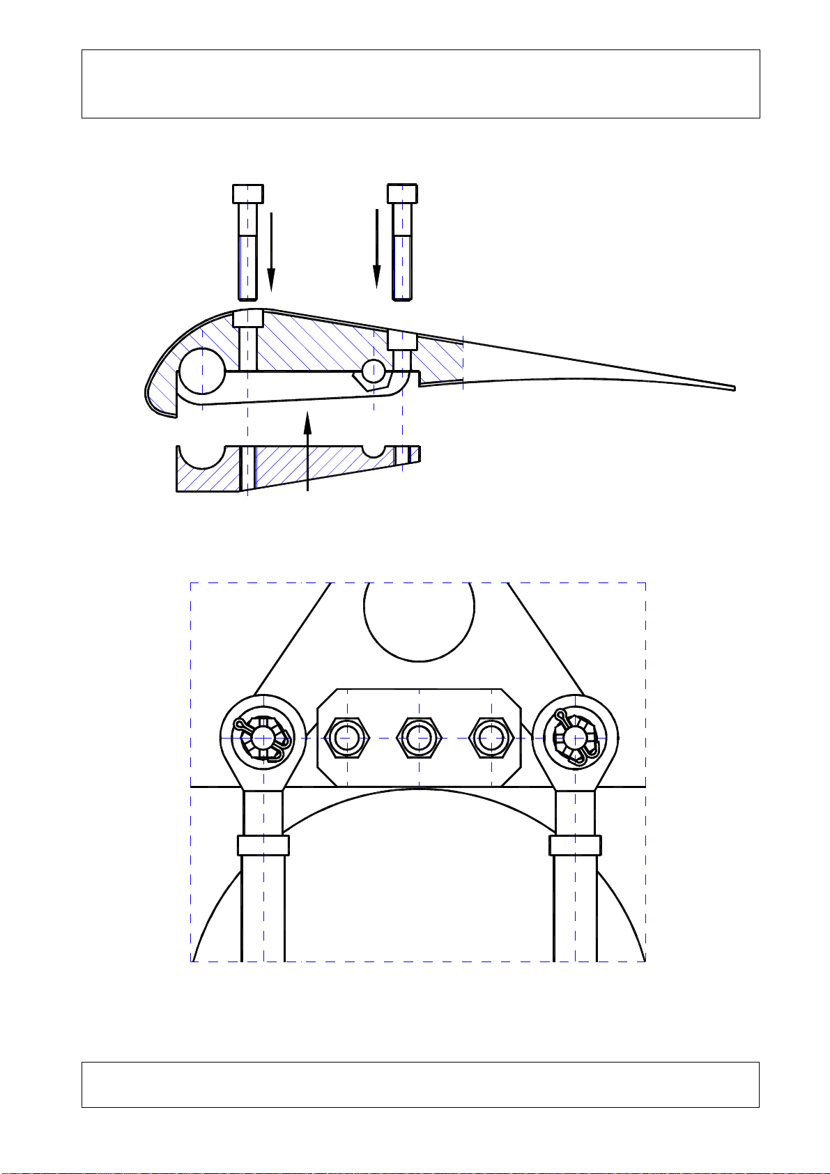
d)Putpinsintothemountingseats(2infrontand 2inback)Frontpinsareto
be inserted afterremoving topwindscreen panel,back pinsaretobe inserted
inthe compartmentarea.Thepinsaretobe securedwithbolts.Boltsareto
be securedwithcotterpins(picture8-2).
e)Flapsdriveistobe connectedbyaclamping ring,secured withbolts.Bolts
aretobe screwed intousing LOCTITE262 fluid.Theymustbe secured with
cotterpinsfromthe bottom(picture8-3).
f)Aileronsdriveistobe connectedinthecockpitthrough placingrods’eyeson
driveleverpinsinthebottompartofthe wing.Tighten the castellated nuts
and securewithcotterpins(picture8-4).
g)Fixthe controldrivecoverand the panelinfront of the windshield.
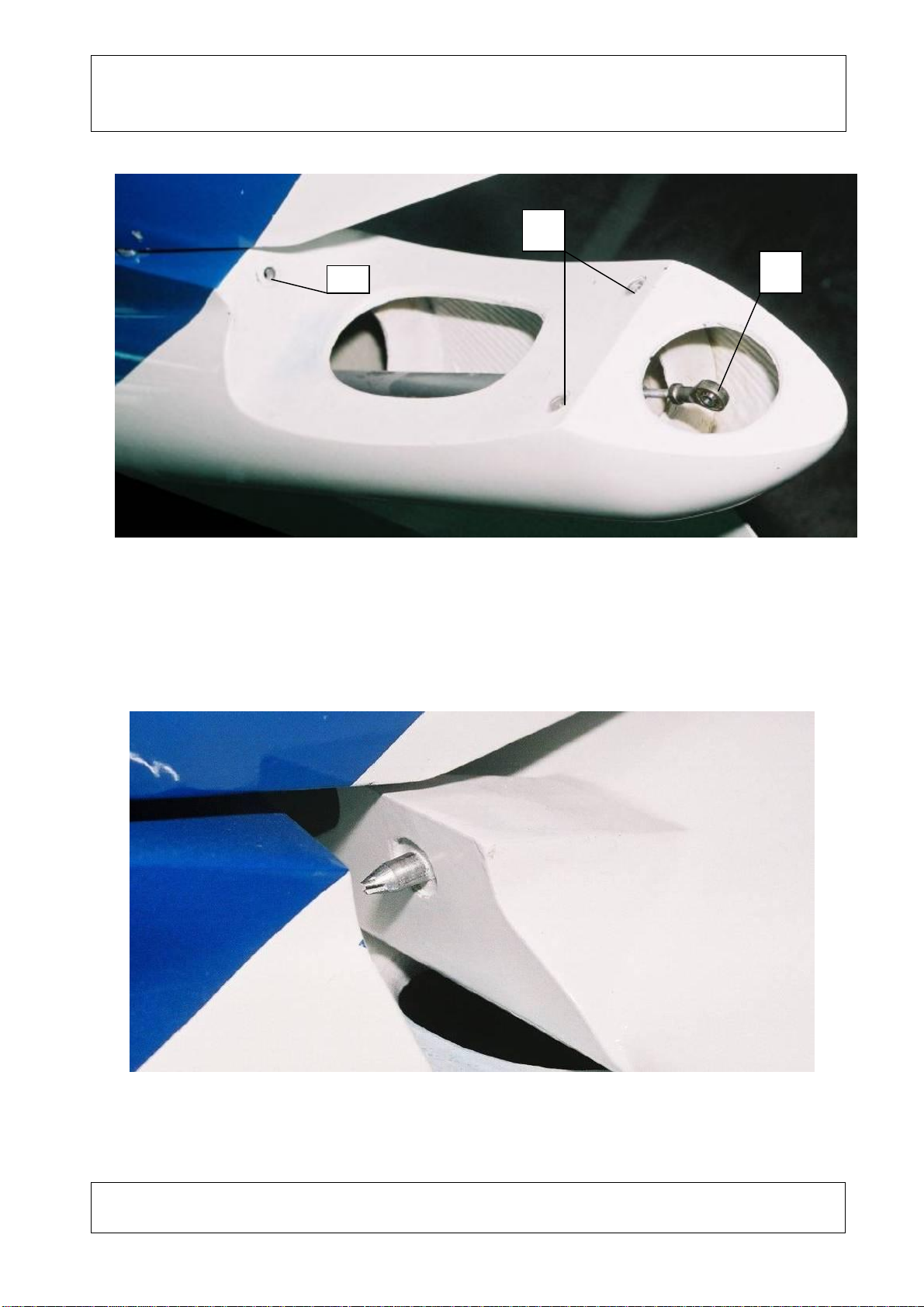
h)Insert the pinlocated inthefront partofhorizontalstabilizer,totheholeinthe
fuselage and tightentwoboltstofixthe stabilizertothe fuselage(pictures8-6
and 8-7)
i)Putelevatorrod eyeontheforkinelevatorcontrollever.Secureitwiththe
pin,screwthe boltinand put the cotterpin(picture8-8)
j)Check performanceof allcontrolsystems, includingflapscontrolsystem.
k)Connect pneumaticpipeswiththePitot pipe.
Disassemblyoftheplaneistobedoneinreverse order.

Manufacturer: PPHU
EKOLOT
Type: KR-030TOPAZ
Handling, Maintenanceand PeriodicInspections
Manual
Issue: 1
Rev. No: Date:July2010
Date: Page
8
Pic. 8-1Placingthe wingon thefuselage
Pic. 8-2Installationof mountingpinstothe fuselage
Manufacturer: PPHU
EKOLOT
Type: KR-030TOPAZ
Handling, Maintenanceand PeriodicInspections
Manual
Issue: 1
Rev. No: Date:July2010
Date: Page
9
Pic. 8-3Flapsdriveconnection
Pic. 8-4Aileronsdriveconnection tothe fuselage
Manufacturer: PPHU
EKOLOT
Type: KR-030TOPAZ
Handling, Maintenanceand PeriodicInspections
Manual
Issue: 1
Rev. No: Date:July2010
Date: Page
10
Pic. 8-5Tailwithout elevatorunit
1
-frontseat formounting the elevatorunit
2
-rearseat formountingthe elevatorunit
3
-elevatorrodeye
Pic8-6
Insertion of elevatorunitpintothe seatinthe fuselage
1
2
3

Manufacturer: PPHU
EKOLOT
Type: KR-030TOPAZ
Handling, Maintenanceand PeriodicInspections
Manual
Issue: 1
Rev. No: Date:July2010
Date: Page
11
Pic. 8-7
Boltsforfixing elevatorunit tothe fuselage
Pic. 8-8
Connecting of elevatorrodtotheelevatorlever

Manufacturer: PPHU
EKOLOT
Type: KR-030TOPAZ
Handling, Maintenanceand PeriodicInspections
Manual
Issue: 1
Rev. No: Date:July2010
Date: Page
12
8ADJUSTMENTPOINTSOFTHECONTROLSYSTEM
8.1Adjustmentofelevator can be donethrough screwinginor outthe
elevator rodeye.See:8-5,pos.3.Locknutmustbe loosenedprior to
thisactivity.When theadjustmentisfinished,thepush-pullrod eye
must besecured withalocknut and Loctite262.
8.2Aileronscontrolsystem isadjustablebychanginglengthofpushrods
(recommended tobe carriedout inEkolotworkshop)
8.3Ruddercontrolsystem isequipped withneutralpositionadjustment
systemwithpedalsinneutralposition,(see Pic.8–10),aswell as
adjustmentofdeflection,bymeansofchanging positionsoflimiters
mounted on thepush-pull rod.
9 Pic. 8-10.Rudderneutralpositionadjustmentpoint
1. Settingtheneutralpositionoftheruder.
2. Removetheadjustment tipof therudderpushrodfromthebolton
the middlelever.
3. Positionpedalinneutralpositionand immobilize.
4. Prior toscrewingtheadjusting tipinorout(see:8-10)neutralposition
of ruddermustbe maintained. Securethe endapplyingthe same
methodasused for rudder assemblycomponents.
Adjustabletipof the
rudderpush-pull rod
Middlelever
Viewof thecentraltunnelfromthen rightsideof
thecockpit
Manufacturer: PPHU
EKOLOT
Type: KR-030TOPAZ
Handling, Maintenanceand PeriodicInspections
Manual
Issue: 1
Rev. No: Date:July2010
Date: Page
13
5. Placealockwasheronthe middlelever, screwinacrownnutand
secure it withapin.
6. Freethe rudder pedal.
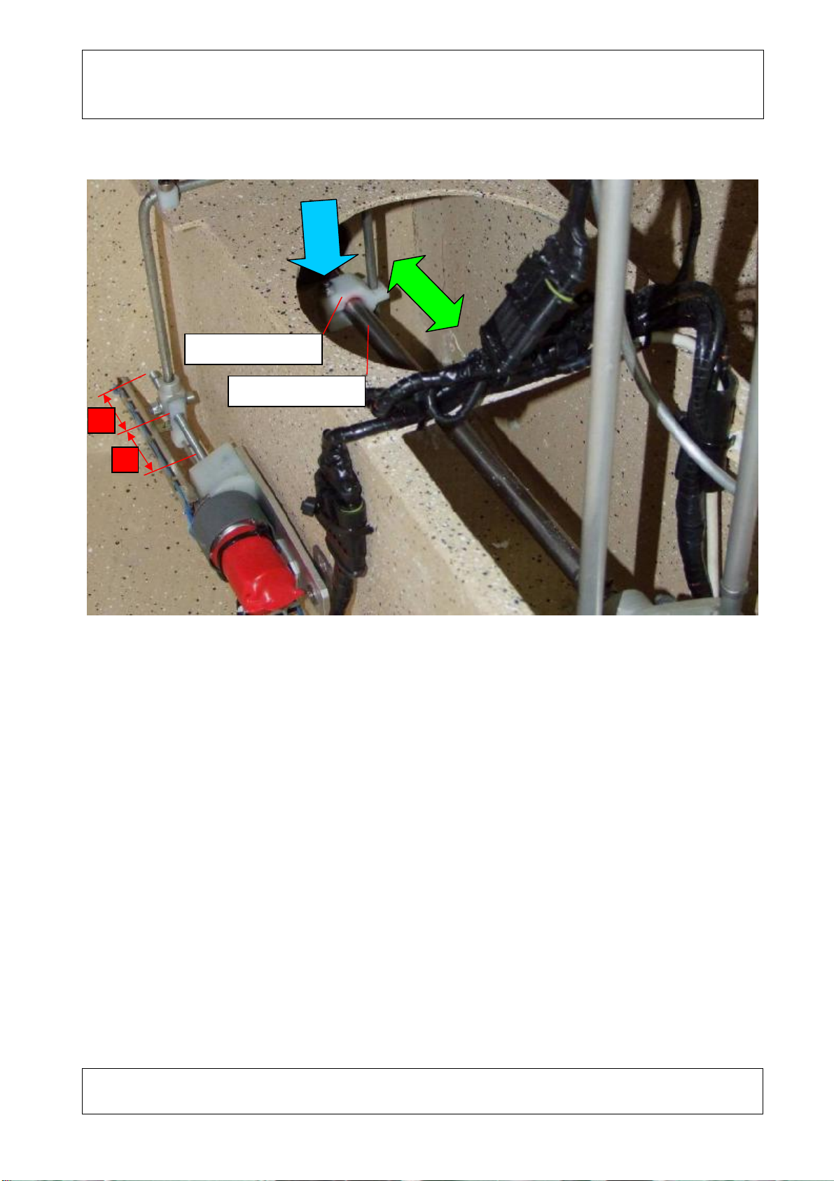
Pic. 8-11.Adjustmentpointof rudderpush-pull rodmovement limiters
(armrestremoved fromthechannel)
7. Identification ofrudder deflection (frontwheeldoesnottouchthe
ground).
8. Loosenthelimiterbolts.
9. Deflect theruddertotheleft tothefull possibledeflection.
10. Pushthefrontlimitertotheretainingplateandclampthelimiteron
the pushrod bymeansoftighteningtheclampbolt.
11. Deflectthe rudder tothe rightand setthe positionoftherearlimiter
similarlytopoint3.
Push-pull
rod
movement
limiters
Rudder
push-pull
rod
Bumper
plate
Manufacturer: PPHU
EKOLOT
Type: KR-030TOPAZ
Handling, Maintenanceand PeriodicInspections
Manual
Issue: 1
Rev. No: Date:July2010
Date: Page
14
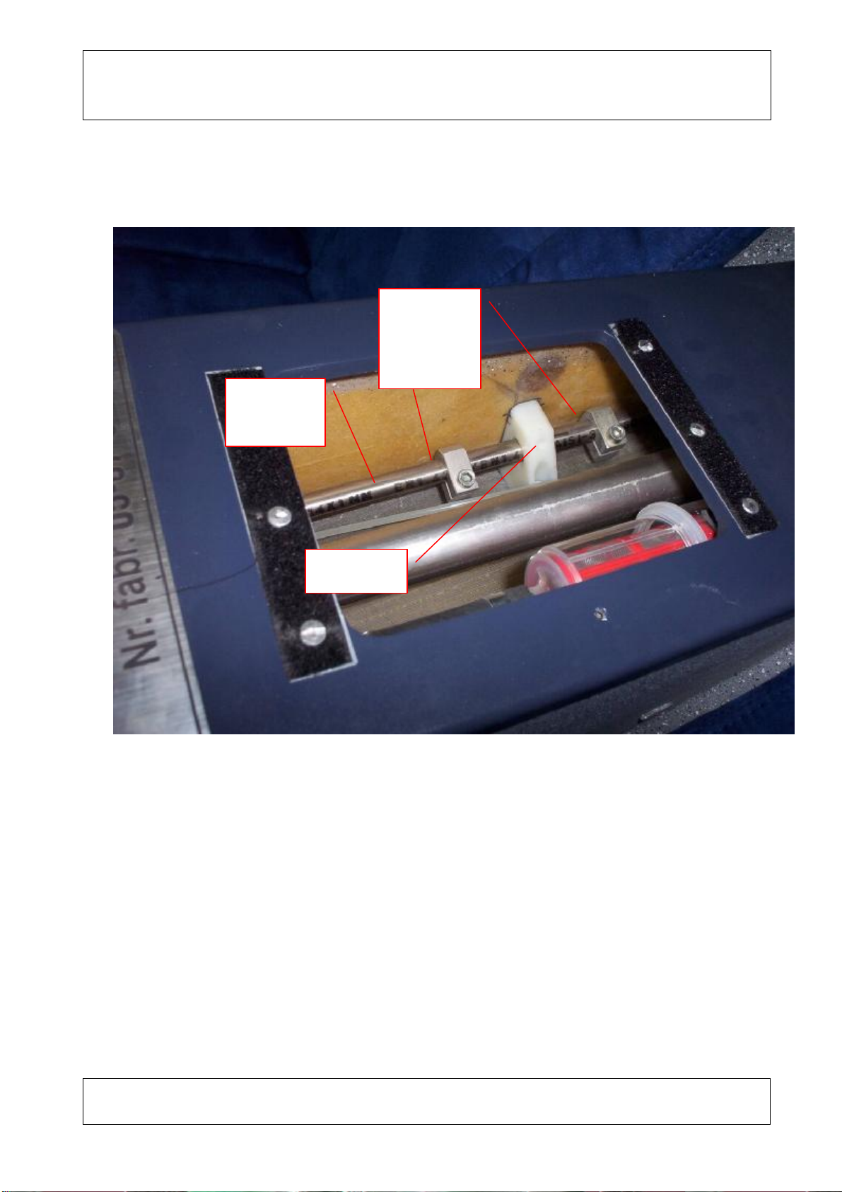
8.4Elevatortrimmeradjustment
1. Usingpressbuttonson thecontrolstick setthetrimmer motorslider
inthecentralposition (dimensions„a”shouldbeidentical)
2. Loosen the boltintheclampJ.12.310.03.00 (blue arrowintheabove
photograph)
3. Movethe clampalongthe rod T.12.121.00.01tothe pointelevatoris
inneutralposition.
4. Tightenthe bolton the clampJ.12.310.03.00 (blue arrowinthe above
photograph)inorder tofixtheclampJ.12.310.03.00on therod
T.12.121.00.01.
a
a
T.12.121.00.01
J.12.310.03.00
Manufacturer: PPHU
EKOLOT
Type: KR-030TOPAZ
Handling, Maintenanceand PeriodicInspections
Manual
Issue: 1
Rev. No: Date:July2010
Date: Page
15
PARTSAND SUBASSEMBLIES TO BEREPLACEDOUTSIDETHE
MANUFACTURER’SFACTORY
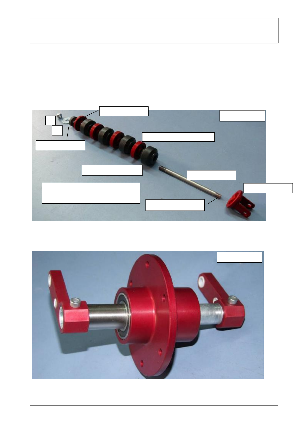
9.1FRONTUNDERCARRIAGE
9.1.1Shock absorberassemblyJ.13.201.00.00
9.1.2Axle,rockerandhubassembly
J.13.201.01.00
J.13.201.01.00
3pcs. J.13.201.02.00
J.13.201.03.00
4pcs. AP.PF 126P
J.13.201.01.00
1
2
1.Washer 5–16 –1,5
2.Nut M5DIN982 UseLOCTITE262
Pic.
9.1.1
Pic. 9.1.2

Manufacturer: PPHU
EKOLOT
Type: KR-030TOPAZ
Handling, Maintenanceand PeriodicInspections
Manual
Issue: 1
Rev. No: Date:July2010
Date: Page
16
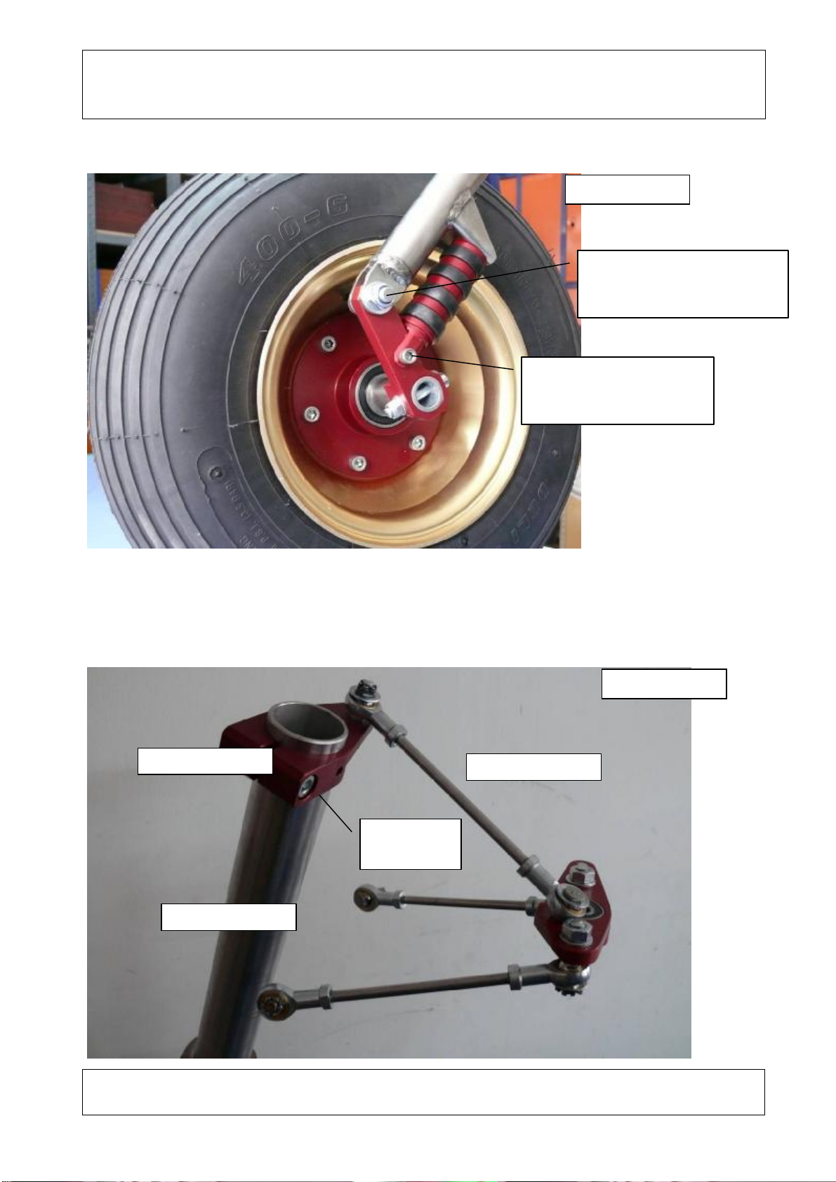
9.1.3ForkassemblyJ.13.200.00.04withshock absorbersJ.13.200.00.00
J.13.130.01.02
J.13.100.01.02
J.13.200.01.00P
J.13.200.01.00L
J.13.200.02.00
J.13.200.03.00
J.13.100.02.00
Bear
ing 6004 ZZzzZ
J.13.200.02.00
J.13.200.03.00
Bearing 6004 ZZ
1
2
3
1
2
3
J.13.200.00.04
J.13.201.00.00
J.13.201.00.00
1.Bolt M6x50 gat. 8,8DIN912
2.Washer 6DIN1440
3.
Nut
M6DIN982
Pic. 9.1.3
Pic. 9.1.4

Manufacturer: PPHU
EKOLOT
Type: KR-030TOPAZ
Handling, Maintenanceand PeriodicInspections
Manual
Issue: 1
Rev. No: Date:July2010
Date: Page
17
9.1.4Completeassembly:hub,rims,tire,innertube
9.1.5Completewheelassemblywithaxleandrockers
Tyre4.00x66ply
1
Innertube 4.00
x6
J.13.130.01.02
6pcs. BoltM6x50,8,8DIN912
2
J.13.130.02.
01
6pcs.Washer 6
6pcs. Nut M6DIN982
1. Part no.42206-0www.ulmtechnologie.com
2. Part no.42206-1www.ulmtechnologie.com
Pic. 9.1.5
Pic. 9.1.6
Manufacturer: PPHU
EKOLOT
Type: KR-030TOPAZ
Handling, Maintenanceand PeriodicInspections
Manual
Issue: 1
Rev. No: Date:July2010
Date: Page
18
9.1.6Wheel mountedonthefork
The othersideof the wheelisidentical.
9.1.7Frontundercarriagecontrol leverwiththepole
(removed fromthe airplane)
BoltM8
Washer 8
Nut M8DIN982
BoltM5
Washer 5DIN1440
Nut M5DIN982
J.13.200.00.04
J.13.122.00.01
T.12.622.00.00
Clampbolt
Pic. 9.1.7
Pic. 9.1.8

Manufacturer: PPHU
EKOLOT
Type: KR-030TOPAZ
Handling, Maintenanceand PeriodicInspections
Manual
Issue: 1
Rev. No: Date:July2010
Date: Page
19
(installed inthe airplane)
9.1.8Removalofwheel fromfork
1.Removethefairingretainingbolts.
J.13.200.00.04
J.13.122.00.01
T.12.622.00.00
BoltM5x10, 8,8DIN912
BoltM5x10, 8,8DIN912
Washer 5DIN1440
Pic. 9.1.10
Pic. 9.1.9

Manufacturer: PPHU
EKOLOT
Type: KR-030TOPAZ
Handling, Maintenanceand PeriodicInspections
Manual
Issue: 1
Rev. No: Date:July2010
Date: Page
20
2.Movethefairing upward, alongthepole.
3.Unscrewthe shockabsorbersmountingbolts.
Pic. 9.1.11
Pic. 9.1.12
Table of contents


