Mountain Models Magpie AP User manual

Magpie AP
Aerial Photography Airplane
Magpie Specifications
Length: 36in.
Wingspan: 54in.
Wing Area: 486in2
Weight (without battery): 19 oz.
Thank you for purchasing the Magpie AP. This model is an elevator/rudder setup, designed as a
dedicated Aerial Photography plane. It is a stable enough plane for the beginner pilot.
Sincerely, Mountain Models
Doug Binder 465 D Street
Penrose, CO 81240
www.mountainmodels.com
Phone: 719.372.6727
Fax: 719.372.3744
Last updated March 6, 2005

Mountain Models Magpie
2
Before You Begin
Before you begin building your Magpie, make sure you read and understand all of the
instructions thoroughly.
Additionally, you will need to have the following items.
What You Will Need
• Smooth and flat work surface
• Wax paper to protect the plans
• Thin Cyanoacrylate (CA) glue
• Foam Safe Glue – 5 minute epoxy, white glue, or foam safe medium CA. We
recommend a tube of 5 minute epoxy.
• Hobby knife with #11 blades
• Needle nose pliers
• Wire cutters
• Sanding block with 200 grit sandpaper
• 2" packing tape or wing tape for covering the wings and fuselage
• 3M77 spray adhesive
• 4- or 5-channel radio rudder/elevator/throttle/camera shutter/camera tilt (optional).
• GWS EPS400C-E motor or brushless motor such as the Feigao 1308416L
• 3 micro servos (4 if you are using the camera tilt option)(we recommend the Hitec
HS55, GWS Pico, or Naro)
• Electronic Speed Control (ESC) capable of handling at least 15 amps
• 1000mAH or higher 2s or 3S LiPoly battery is recommended for weight savings
Parts List
Quantity Description of Part
Wood
1 1/32” Laser cut plywood sheet
1 1/32” Laser cut plywood wing spar
1 1/16” Laser cut plywood sheet
1 1/8” Laser cut plywood sheet
Foam
2 Wing sections
2 Fuselage sections
5 Depron tail surfaces
Additional Parts
1 1/8” round x 7 3/16” hardwood dowel
2 1/8” round x 2.5” hardwood dowel
2 6” heat shrink tubing
1 6” Velcro strip for mounting the battery
1 180” plastic strapping
2 1/32” x 18” thin music wire for the pushrods
1 Bent aluminum landing gear
2 1-3/4” Dubro SL tires

Mountain Models Magpie 3
Quantity Description of Part
2 1” 4-40 hex-head screw
4 4-40 nylon-insert lock nuts
1 #2 x 3/8” motor retaining screw
1 2.25” of 1/16” music wire
4 #6 Blind Nut
4 #6 Washers
4 #6 Hex Head screws
1 1/4-20 Bolt
General Building Tips
• Use only foam safe glue to attach the foam sections. Regular CA will dissolve the
foam.
• Don’t remove any pieces from the balsa sheets until they’re ready to be used. That
way, parts won’t get mixed up or disappear.
• After you remove pieces from the balsa sheets, carefully remove any of the extra
material from where the piece was attached.
• Don’t over force your pieces together. If they aren’t going together properly, make
sure you have the right pieces and that they are oriented correctly.
• If you want to remove the charred edges caused by the laser cutting process,
dampen a cloth with bleach and gently rub the affected areas. Removing the char
will not increase the strength but will make it look better.
Assembly Instructions
Assemble the Wing
The first thing you are going to assemble is the wing of your airplane. This involves
assembling the wing halves, inserting the vertical spar, attaching the spar strips, and then
applying the packing tape.
Do not let non-foam safe CA touch the foam. Regular CA will dissolve the foam.
1. Glue the wing halves together with 5 minute epoxy or white glue. You can hold them
together with tape while the glue sets. Be sure that the two halves line up correctly.
Do not worry about the dihedral angle. The wings are cut with the proper angle at
the factory.

Mountain Models Magpie
4
2. Using a sharp exacto blade, cut a slit through the wing in the center of the spar slot
12.5” long from the center on each side. Apply a little white glue or epoxy to both
sides of the 1/32” plywood vertical spar. Insert the vertical spar so that it goes
completely through the wing without extending beyond the surface of the wing on
either the top or the bottom.
3. Install the spar strips. Measure and cut two lengths of 1/2" plastic strapping so that
they are the length of the wing. Sand the strapping to help the glue adhere.
This is very important. Lay a strip down on a sheet of wax paper and apply epoxy
to the strapping, ensuring that there is an even layer of epoxy with no dry areas.
Lay the strapping in the notch on the wing and apply a length of wing tape or
packing tape over the strapping to hold it in place. Install the second spar in the
same manner. Give the epoxy a chance to set up before moving on to the next step.
4. If you prefer, you may shape the wingtips. I like to cut a radius into the front of the
wingtip to give the wing a more sweeping look. This is also a good idea if you expect
to be crashing as it makes the wingtip stronger. Cut the radius with an xacto then
sand the cut even and rounded.

Mountain Models Magpie 5
Covering the Wing
Next, you are going to cover the Magpie wing using either colored wing tape, or clear
packing tape. You can use additional colored tapes to give your wing detail.
Choosing a Pattern
Make sure you choose a high contrast pattern using at least two colors, with the darker
color on the bottom and the lighter color on top. This will help you differentiate up from
down and left from right. Try drawing your pattern out on paper before attempting it on
your wing.
Applying the Covering Tape
For the Magpie, we recommend using wing tape (a colored tape) which can be purchased
from Mountain Models or clear packing tape which can be purchased at many office supply
stores. You may also cover the wing in low temperature iron on covering. If you choose to
use iron on covering, be very careful with the iron temperature or you will melt the foam.
Test the covering on a scrap piece of foam first.
1. Lightly sand the entire wing. Remove all the dust or the tape will not adhere.
The adhesive spray is known to contain acetone which will eat foam. In order to
minimize the problems, you must have a clean nozzle emitting a fine mist, which is
kept a good distance away from the wing and moved quickly. Apply a very light
coating on the surfaces, allow some dry time, and then apply another light
coating, letting it evaporate a bit before bonding. The slight eating of the foam
ends up being part of the bond.
2. Spray the wing with 3M 77 and let it set for about 5 - 15 minutes, until it is tacky.
3. Reinforce the center of the wing where it will be held on with rubber bands. Do this by
laying down 4 strips of tape, 4” long on the top of the trailing edge of the wing,
overlapping the bottom of the wing by ½”. Do the same for the leading edge.
4. Starting from the trailing edge, run a strip of tape across the length of one wing,
overlapping the center by one inch. The first strip should wrap around the trailing edge by
1/2". Continue laying down strips of tape to cover the bottom of your wings, overlapping

Mountain Models Magpie
6
each piece by 1/4" or more. The tape should also extend past the wingtip where you will
wrap the tape around the tip before trimming.
Keeping your scissors or hobby knife clean is very important to the covering
process. After every five to ten cuts, wipe your blade with a Windex dampened
paper towel. The residue from the tape can make clean cuts almost impossible
since the tape will stick to the blades and just rip instead of cut.
5. Repeat Step 3 for the rest of your wing.
You can use permanent markers to decorate your covering if you don't want to add
weight or covering complexity.
Smoothing out the Covering Tape (Optional)
Using a heat gun or hair dryer, you can carefully shrink the tape until you get a glassy
finish. This is not a required step, but will make the surface look more polished. Be very
careful as the tape can shrink enough to pull away from the adjoining tape. It is also very
easy to melt the foam. Start with the gun on a low setting and increase the heat till the
tape just starts to shrink. Too much heat is a bad thing.
1. Start shrinking the bottom of the wings first, beginning at the leading edge and moving
towards the trailing edge. Do the middle areas last.

Mountain Models Magpie 7
2. Follow the heat gun's path using a covered hand (you can use a thick, clean sock or a
towel), pressing down firmly, smoothing the surface and allowing the tape to adhere to
the adhesive.
3. Once the bottom is done, shrink the top in the same fashion.
Assemble the Camera Mount Base
Before assembling the fuselage, put the camera mount base together. This will ensure that
the glue joints are dry when you insert the mount into the fuselage.
1. Glue the two 1/16” plywood camera mount base sides to the two 1/16” plywood wing
saddles. Make sure that they are pressed well in and there is no gap between the two
parts. Glue with thin CA. The scribe lines on the wing saddle pieces will face the inside of
the camera mount base, so you are designating right and left sides here.
2. Press the four blind nuts into the holes in the 1/8” plywood; two for the landing gear base,
and one each on the front and rear ends of the camera mount base. This may take a bit
of hammering as the holes are cut to be snug and you need the nuts pressed completely
into place.
3. Attach the landing gear plate to the front wall of the camera mount base as in the photo,
noting the orientation of the blind nuts. Do not glue yet.

Mountain Models Magpie
8
4. Attach the assembly from step 3 to one of the sides of the camera mount base as in the
photo. Make sure they are seated well, then glue all the joints with thin CA.
5. Glue the other camera mount base side to the front plate and landing gear. Glue with thin
CA.
6. Attach the rear camera mount base plate. Again, note that the blind nut orientation is
coming from the rear side. Glue with thin CA and flow more thin CA into all the joints—
this is the mount that will hold your expensive camera, so make sure it is secure.
NOTE: Do not try to insert the camera mount base assembly into the foam of the fuselage until the glue
is completely dry, as thin CA will melt the EPS foam.
Assemble the Fuselage
You will assemble the fuselage by first gluing the two fuselage halves together, adding four
pieces of strapping plastic for reinforcement, inserting the camera mount base/wing saddle
assembly, sanding to shape, adding servo mounting plates, then taping the fuselage. Follow
along carefully as there are a few critical steps along the way.
1. Glue the two fuselage halves together. Note that the rear section of the fuselage is
slanted down to the tail on top and flat on the bottom. Place a protective wedge that
came with the rear fuselage under the rear half to help make the two sections meet. You

Mountain Models Magpie 9
can use epoxy, white glue, or foam safe CA. Hold the fuselage halves together with tape
till the glue sets. Take great care to keep the fuselage straight.
2. The rear of the fuselage is tapered, making it difficult to apply the strapping plastic in the
next step as the fuselage will bend when you press down on the strapping plastic. As
noted in step 1, if you shim the back with the wedges that were cut from the rear
fuselage, it will be much easier to keep the fuselage straight.
3. Glue the four fuselage reinforcement straps into place. Measure and cut two of the 1/2"
plastic strapping at 6”, so that they fit from the motor cutout to the front of the camera
opening on either side, and another two 19.75” pieces from the rear of the camera
opening to the tail. Don’t forget to sand the strapping plastic before you glue it.
Position the bottom of the strapping an even 1.75” up from the bottom of the fuselage on
the front, and 1.5” up from the bottom of the fuselage on the rear. Glue as you did the
wing spar and hold the strapping down with wing tape or packing tape. The tape can be
removed when the epoxy is set.
NOTE: This is your last chance to make sure your fuselage is straight. Sight along
the top of the fuselage from front to back and check for any curving. The strapping
can correct a curved fuselage but, if you are not careful, can make the fuselage
curve.
4. If you wish, you may sand the fuselage to round the edges as shown in the photo below.
Start with 220 grit sandpaper and round the top and bottom. You will find it easer if you
only sand in one direction. I like to completely round the top and bottom but just a little is
fine. You'll want to sand outside as the foam dust will make quite a mess. Remove as
much of the foam dust as possible before continuing. DO NOT SAND THE WING
SADDLE (The area where the wing meets the fuselage).

Mountain Models Magpie
10
5. Mount the rear servo reinforcement plates so that the elevator servo plates are 1" in front
of the horizontal stabilizer and the bottom of the plates are just above the plastic strap.
The rudder servo plates are just below the plastic strap. Separate the plates enough so
that your servos will fit between them with about 1/16” extra gap. Glue the plates with
an even layer of epoxy.
6. Install the camera mount base. Place a layer of white glue or epoxy along the wood
surfaces that will contact the foam. The front end will be carrying most of the weight and
taking the landing stress, so take care that it is glued well. Slide the camera mount
base/wing saddle into place. The scribe lines on the inside of the wing saddle should be
just visible above the fuselage, so you can use them to ensure that the right and left sides
are lined up evenly. The landing gear plate will sit in the cutout on the front fuselage
bottom so it is flush with the foam.
7. Lightly spray the entire fuselage with 3M77 and completely tape the fuselage, including
the camera mount base/wing saddle with wing tape. I find it easiest to start with the
bottom. To wrap the tape around compound curves, you can make small slits in the tape
along the curve and perpendicular to the curve. Make sure to wrap completely around the
rear of the fuselage. When you are done taping, you will need to go back and cut the tape
away from the horizontal stabilizer slot, the motor mount slot, and the left side of the
receiver hole (the opening under the wing saddle.

Mountain Models Magpie 11
8. Put a fresh blade in your xacto and cut out holes in your fuselage for your servos. You
will use the servo plates as a guide and cut the width of the slots 1/16" narrower than the
width of your servos. This will give the servos a nice tight fit. I like to not cut completely
through the fuselage and just work the foam out with a screwdriver. This is just for
looks.
Building and attaching the motor mount
There are two types of motor mounts provided: a GWS stick type mount and a
firewall type mount. If you use the GWS EPS motor, you will use the stick
mount. We will only describe the stick type mount as the firewall mount is quite
similar.
1.Glue the motor mount together with thin CA. Be sure that the glue is
completely dry before sliding the mount into the fuselage as the uncured CA
will dissolve the foam.
2. Ensure that a GWS type motor/gearbox will slide over the mount stick. You
may need to sand the motor stick a bit to get the motor on.
3.Slide the motor mount into the fuselage and tape it into place. One piece of
wing tape per side will hold the mount in nicely. In the photo, the mount is
not taped yet. You can angle the mount to the right before taping to give
the motor some right thrust. About 3 degrees should be right.

Mountain Models Magpie
12
Installing the Landing Gear
1. Install a 1” 4-40 bolt through one wheel. Put a locking nut over the screw end and
tighten it down to hold the wheel so it can spin freely without any slop. Slide the
bolt through the landing gear from the outside, and retain it in place by firmly
screwing on a second locking nut. Repeat this step with the other wheel, bolt, and
locking nuts.
2. Install the landing gear to the landing gear mount with the off-center holes nearer to
the front of the fuselage. Secure the landing gear in place with the hex-head bolts
and washers.
3. Cut a slit in the bottom rear of the fuselage for the tail skid. Apply a coat of epoxy
or white glue to the skid and press it into the slit.

Mountain Models Magpie 13
Assemble and Install the Stabilizer, Rudder, and
Elevator
4. Glue the vertical stabilizer to the top rear of the fuselage, flush with the rear of the
fuselage. To make hinging the rudder easier, I prefer to offset the vertical stabilizer
to the left so that the left side of the stabilizer is in line with the left edge of the rear
of the fuselage. You will need to remove the tape from the fuselage where the
vertical stabilizer will be glued.
Vertical Stabilizer in line with left edge.
5. Cut a 45 degree bevel along the trailing edge of the horizontal stabilizer. This is so
that the elevator can deflect down without interfering with the horizontal stabilizer.
I like to use an xacto knife to cut the bevel. I lay a straight edge along the trailing
edge and angle the knife inward.
Mountain Models Magpie
14
6. Join the two elevators together with the 7 3/16”dowel. Use the horizontal stabilizer
as a guide to set the distance between the two elevators. The outer tips of the
elevators should line up with the tips of the horizontal stabilizer. If you run the end
of the dowel along the edge of the elevator where you will be gluing the dowel, you
will create a groove for the dowel to set in. Glue with epoxy. Ensure both elevators
remain flat while the glue dries. I find it helpful to hold the dowel on place with
packing tape as the glue dries.
7. With a sharp xacto and a straight edge, cut a 45 degree bevel in the leading edge of
the rudder. The bevel in the rudder will angle so that the furthest forward point (the
part that will be hinged to the fuselage) is on the left.
8. There are two control horn reinforcement plates. Slide a control horn into the plate
and epoxy the plate and horn to the top of the elevator into the provided slot. The
horn will be in the left elevator as shown in the above photo.
9. Follow the same procedure for the rudder horn. The rudder horn will be on the left
side of the rudder.
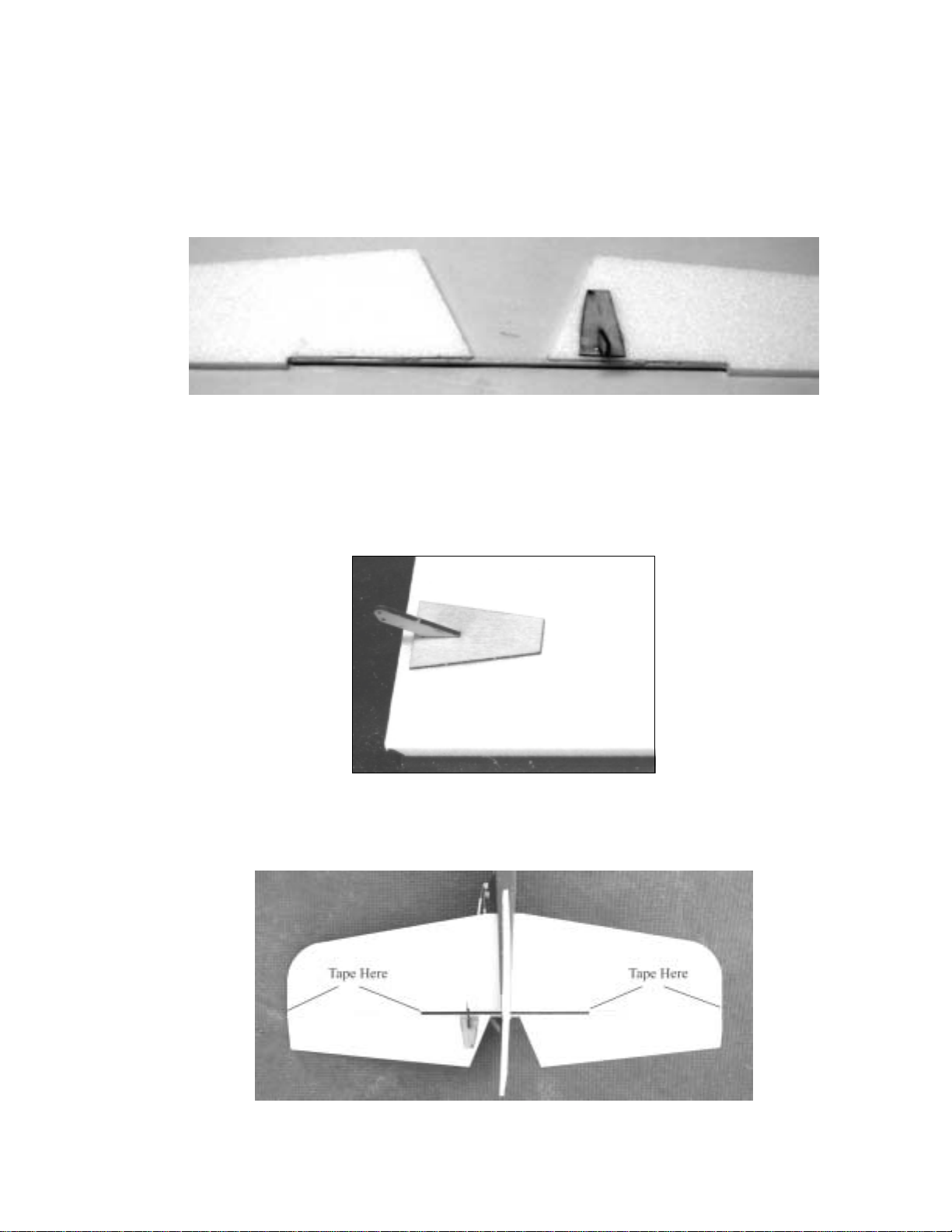
10. Tape the elevator to the horizontal stabilizer with packing tape so that, with the
hinge on top, the control horn slot is on the left elevator. The elevator should just
kiss the stab but should also be able to deflect 45 degrees or more in both
directions. In the photo, the horizontal stabilizer is installed in the fuselage. We will
do that later.

Mountain Models Magpie 15
11. If there is any doubt as to the strength of the tape hinge, you can flip the elevator
over onto the stab and hinge the other side of the joint.
12. Slide the horizontal stabilizer into the slot in the rear of the fuselage so the hinge is
facing up and glue with foam safe CA, white glue, or epoxy. Ensure that the
stabilizer is square to the fuselage.
13. Hinge the rudder to the rear of the fuselage the same way you hinged the elevator.
You will need one piece of tape below the rudder control horn, and another above
the elevator to the top of the rudder. The hinge will be on the left side of the
fuselage.
Install the Elevator and Rudder Servos
You should center your servos before you hook them up to the pushrods. To do
this: Connect your servo to your receiver, connect your ESC to your receiver, turn
on your transmitter, and then connect your batteries to your ESC. Your servos will
move to a neutral position, assuming all of your radio trims are set to zero (0).
1. Press the servos into the slots you made in the fuselage build. You will need servo
extension cables as your servo cables will not be long enough to reach the receiver.
You can either tape the cables to the side of the fuselage or cut a slot into the
fuselage as shallow as possible and press the wires into the slot. Close the slot up
with tape.
2. The pushrods are made from two pieces of 1/32" x 5.5” music wire with a Z bend on
one side. One Z bend goes in the servo horn and the other Z bend goes in the rudder
or elevator control horn. The two wires are joined with a piece of heat shrink tubing.
Be very careful shrinking the tubing as the foam melts easily. Once the pushrods
are adjusted to the correct length, where the servo horn is centered and the tail
surface is straight back, carefully place a drop of thin CA on the end of the heat
shrink so that it will wick into the tubing. This creates a very strong joint.

Mountain Models Magpie
16
Install the Wing
1. Slide the two 1/8” x 2.5” dowels through the holes in one wing mount, through the
fuselage, and through the hole in the other wing mount. You will probably not need
to glue the dowels in place.
2. Set the wing on the mount and secure it with 6 rubber bands.
Install the Motor
You will need:
• Motor/gearbox (not provided with kit)
• #2 x 3/8” motor retaining screw (Bagged Parts)
! Installing the Motor
1. Slide the motor over the motor mount stick and slide the motor as far back as possible.
2. Using a small drill bit or the tip of an xacto, start a hole in the side of the gearbox for the
motor retaining screw. Screw in the motor retaining screw and then install the propeller.
If you are using a GWS propeller, make sure the print on the blades is facing
forward.

Mountain Models Magpie 17
Install the Receiver and Speed Controller
We are not going to cover the receiver and speed controller (ESC) specific information,
please refer to your manufacturer’s instructions for more information, if necessary.
Attaching the Receiver
• The receiver is positioned in the cutout in the fuselage below the wing. Connect the
servos and ESC to the receiver, following the guides on the receiver itself. The
channel that you plug the ESC and servos into are dependent on the transmitter.
For example, a Hitec transmitter uses channel one for the rudder (or aileron if you
have the SP wing), channel two is elevator, and channel three is the throttle. Other
brand transmitters may assign channels differently.
• Once the receiver is installed, you can close the fuselage opening with some wing
tape.
Attaching the ESC
• The speed controller (ESC) is attached to the side the fuselage with the supplied
Velcro. Do not make a cutout in the fuselage for the ESC as the ESC must be
exposed to the air for cooling. Connect the battery to and the motor to the ESC,
following the guides on the controller itself.
Installing the Camera Cradle
1. Glue the two camera cradle sides to the camera cradle bottom. Ensure that the parts fit
snugly and that the sides are perpendicular to the bottom. It is best to glue this with
epoxy because it creates a more secure joint.
2. Using the socket-head screws and washers, install the cradle to the camera mount base
with the side that has the four holes in the rear. If you are going to manually adjust the
camera angle, you will set the angle then tighten down on these screws. If you are going
to use a servo adjustable camera tilt, apply a small drop of thick CA on the screw threads
and tighten the screw so that it is almost snug but the cradle can still swing freely.
3. Servo adjustable tilt: You should have two rectangular pieces of 1/8” ply left over. Glue
one of these pieces above the cradle as shown below.
4. Cut a piece of 1/32” music wire 1.5” long. Make a 90 degree bend 1/8” from one end.
Find the 2.25” piece of 1/16” music wire and make a 90 degree bend 3/16” from one end.
Attach the two pieces of wire with heat shrink as shown below.

Mountain Models Magpie
18
5. We need to make a pushrod that can switch between two holes, depending on what side of
the plane the camera is mounted. The cradle will be set up to rotate 90 degrees and we
want to select between horizontal from the right to straight down, or straight down to
horizontal on the left. You will glue the servo to the side of the fuselage so that the
pushrod is pinched between the servo control horn and the 1/8” ply you glued in step 3.
This makes it easy to pull the pushrod out of the hole in the cradle to switch holes, but the
pressure on the servo arm will keep the pushrod in place during flight.
6. I find it advisable to wrap the servo in wing tape before gluing. Roughen the tape on the
servo and the fuselage to get a good glue bond between the two tape surfaces.
7. Once you are satisfied with the movement of the cradle, apply a drop of thin CA to the
pushrod to prevent it from slipping.
8. I control my tilt with my flap knob and activate my shutter with my rudder stick. My
rudder is on my aileron stick.
Finishing the Kit
Well, you’re almost there…the end is in sight; just a few more steps and you can go flying,
assuming the weather is cooperating.

Mountain Models Magpie 19
Setting the Center of Gravity
The Center of Gravity (CG) will affect how the airplane recovers from a nose up or nose
down condition (pitch stability). With the CG too far forward, the plane will be quite stable,
but require a lot of up elevator to fly level. This will result in an increased low end speed. On
the other hand, too far back and the plane will be hard to control, requiring constant input
to keep the plane flying straight and level. Set the CG .25”-.5” behind the rear of the wing
spar. You adjust the CG by moving the battery as follows.
Attaching the Battery
1. With the battery resting on the wing, adjust the battery fore and aft to find where it will
need to be positioned to achieve the correct CG.
2. Attach the Velcro to the side of the fuselage below the wing such that the battery will be
centered on the Velcro.
3. Attach the soft side of the Velcro strip to the side of your battery pack.
Setting the Control Throws
You need to adjust your radio trim so that the elevator, rudder, and ailerons are all level.
The throws are as follows:
Low Rates High Rates
Elevator +-.5 inch +-1 inch
Rudder +-.75 inch +-1.25 inch
If you are new to flying, set up your controls so that the maximum deflections measured
from the furthest point back on the control surface, are what is specified in the low rates
column. The plane will be fairly gentle set up as such. If you are brand new to flying and
will be teaching yourself, you might want to set the rudder throws to +- .5” and the elevator
to about 3/8”. These soft controls will help to keep you from over controlling.
Setting the Lateral Balance
The lateral balance is along the length of the airplane. If you mount the battery on one side
of the fuselage, the balance will be off. You can easily check the balance by resting the
propeller shaft on a finger and gently lifting the rudder with your other hand such that the
airplane is completely off the ground. If the plane rocks to one side, the balance is off. I
found that, on my Magpie, a quarter and a nickel on the wingtip opposite the battery was
required when I used 1200mAH Lipoly cells. I cut a slip in the wingtip and pressed the coins
in the slit then taped the slit shut.
A word on activating the camera shutter
Because of the many types of cameras, I can’t advise on how to activate your camera
shutter. If you are lucky, you may have a camera that has an aftermarket radio activated
shutter control available. Some are available for the Pentax S5 and some Nikons. If a
remote shutter control is not available, it will be necessary to rig a servo such that the servo
can press the shutter button. A search on www.rcgroups.com in the AP forum will show a
number of creative ways to use a servo.
Table of contents
Popular Aircraft manuals by other brands

Remos
Remos GX Pilot operating handbook

Eiri-Avion
Eiri-Avion PIK-20 Repair manual

Ozone
Ozone Kona Pilot's manual

Piper Aircraft Corporation
Piper Aircraft Corporation PA-28-181 Airplane Maintenance Manual

ICARO paragliders
ICARO paragliders CYBER TE manual

Diamond Aircraft
Diamond Aircraft DA 42 NG Service information


SOUTHPAW
SOUTHPAW 6550 instruction sheet

Cessna
Cessna 1969-1976 172 Series Service manual

Tomahawk
Tomahawk SLINGSHOT 21310 manual

AEROPLANE HEAVEN
AEROPLANE HEAVEN ELECTRA 10A flying guide

bautek Fluggeräte
bautek Fluggeräte FIZZ owner's manual

czech sport aircraft
czech sport aircraft SportCruiser Maintenance manual