manuals.online logo
Brands
  1. Home
  2. •
  3. Brands
  4. •
  5. Aquila
  6. •
  7. Aircraft
  8. •
  9. Aquila AT01-100A 2021 Owner's manual

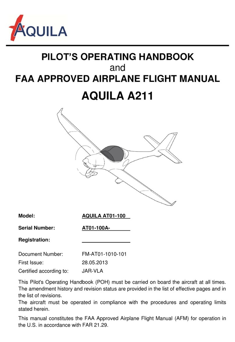
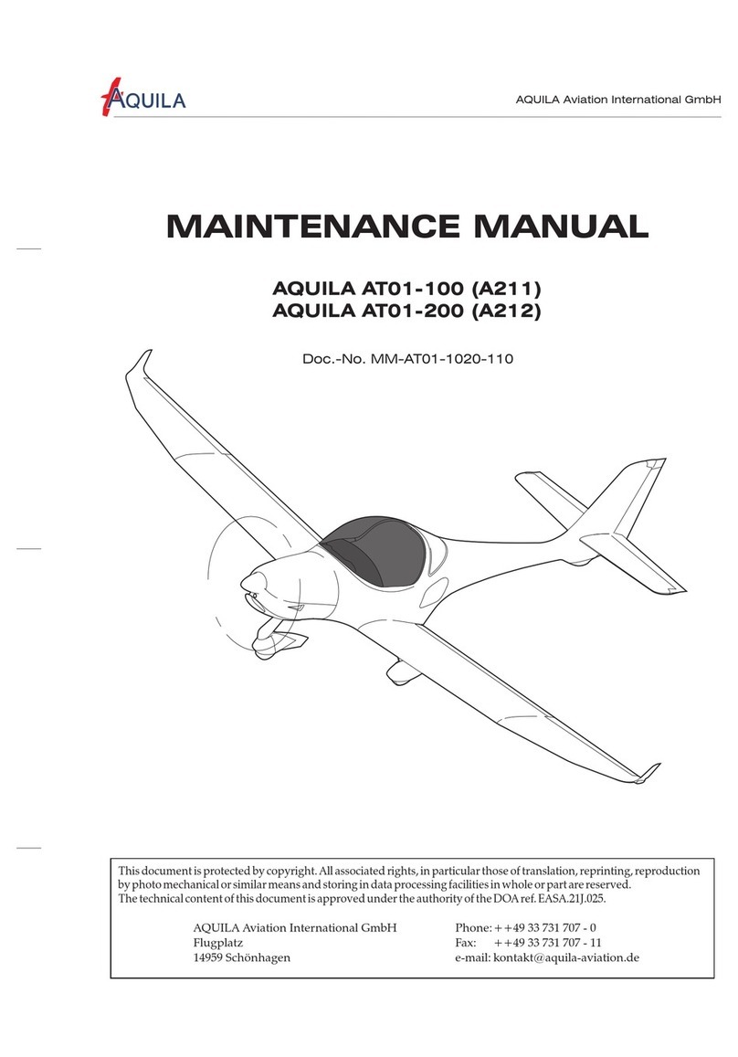
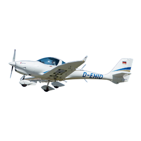
Aquila AT01-100A 2021 Owner's manual

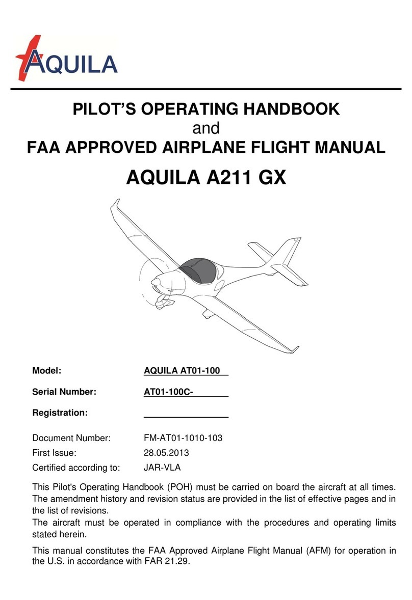
POH / AFM
AQUILA AT01-100A Section 0
Document Nr.: Issue: Supersedes Issue: Date: Page:
FM-AT01-1010-101 A.09A.08 (25.05.2020) 03.03.2021 0 – 1
INTRODUCTION
With the AQUILA AT01 you have acquired a very efficient training and utility aircraft, which is
easy to operate and exhibits excellent handling qualities.
To ensure reliable operation and trouble free flight, we recommend that you read this Pilot's
Operating Handbook thoroughly and adhere to the operating instructions and recommendations
given herein.
CAUTION
All limitations, procedures and performance data contained in this handbook are EASA/FAA
approved and mandatory. Failing to follow the procedures and limits set forth in this handbook
can lead to a loss of liability by the manufacturer.
THE HANDBOOK
The handbook is presented in loose-leaf form to ease the substitution of revisions and is sized
in A5-format for convenient storage in the aircraft.
Tab dividers throughout the handbook allow quick reference to each section. A Table of
Contents is located at the beginning of each section to aid the location of specific data within
that section.
All rights reserved.
Reproduction or disclosure to third parties of this document or any part thereof is not permitted,
except with the prior and express written permission of AQUILA Aviation International GmbH.
Copyright © by Aviation International GmbH
Schönhagen, Germany
POH / AFM
AQUILA AT01-100A Section 0
Document Nr.: Issue: Supersedes Issue: Date: Page:
FM-AT01-1010-101 A.09A.08 (25.05.2020) 03.03.2021 0 – 2
TABLE OF CONTENTS
SECTION
GENERAL 1
OPERATING LIMITATIONS (approved section) 2
EMERGENCY PROCEDURES (approved section) 3
NORMAL PROCEDURES (approved section) 4
PERFORMANCE (partly approved section) 5
WEIGHT AND BALANCE 6
AIRCRAFT AND SYSTEMS DESCRIPTION 7
HANDLING AND MAINTENANCE 8
SUPPLEMENTS 9
POH / AFM
AQUILA AT01-100A Section 0
Document Nr.: Issue: Supersedes Issue: Date: Page:
FM-AT01-1010-101 A.09A.08 (25.05.2020) 03.03.2021 0 – 3
LIST OF EFFECTIVE PAGES
Note:
If the applicable POH / AFM supplement for Night VFR operation is implemented, the list of resulting effective
chapters can be found in chapter 9.
Section
Issue Approved Page Date
0 A.09 0-1 to 0-6 03.03.2021
1 A.08 1-1 to 1-12 25.05.2020
2 A.09 X 2-1 to 2-10 03.03.2021
3 A.08 X 3-1 to 3-16 25.05.2020
4 A.09 X 4-1 to 4-18 03.03.2021
5 A.05 (X)* 5-1 to 5-22 26.06.2017
6 A.02 6-1 to 6-14 15.10.2013
7 A.08 7-1 to 7-22 25.05.2020
8 A.09 8-1 to 8-6 03.03.2021
9 A.09 9-1 to 9-2 03.03.2021
*- partially approved
POH / AFM
AQUILA AT01-100A Section 0
Document Nr.: Issue: Supersedes Issue: Date: Page:
FM-AT01-1010-101 A.09A.08 (25.05.2020) 03.03.2021 0 – 4
LIST OF REVISIONS
All revisions to the handbook, with the exception of individual weight and balance data and
revisions to the Equipment List, must be recorded in the List of Revisions. Revisions must
either be approved by EASA or, in the case of changes, in accordance with Part 21A.263(c)(2)
by the Design Organization of AQUILA Aviation International GmbH.
Additions and revisions to text in an existing section will be identified by a vertical black line
adjacent to the applicable revised area. A new issue code appears in the footer of the revised
pages.
If revisions are distributed, the applicable sections are to be exchanged with the updated
version. Generally only complete sections of the POH will be exchanged, and not individual
pages.
The operation of the AQUILA AT01 is only permitted with a current and up to date POH carried
on board. Please refer to the following web page whenever the revision status of your POH is in
question.
www.aquila-aviation.de
Issue Description of Revision Revised
Section(s)
EASA
Approval-
number
Approval by
AQUILA / EASA
Date / Signature
A.01 First Issue All 10045112 29.05.2013
A.02 Editorial changes,
Supplements 8,33 kHz
FAA certification All 15.10.2013
A.03 AS-00 „Winter Operation“ 0, 9 08.04.2014
A.04 Editorial changes 0, 4 19.10.2015
A.05 Minor changes, AS-21 “GTX
335 / 345”, SB-AT01-029
incorporated 0, 2, 3, 5, 7, 9 26.06.2017
A.06 Editorial changes, AS-23 „G5
AI / HSI“ 0, 1, 9 01.06.2018
A.07 AS-24 "AT-1" 0, 9 18.06.2019
A.08
Editorial changes,
AS-25 "Garmin G3X"
0, 1, 2, 3, 4, 7, 9 10073568 25.05.2020
A.09
Editorial changes,
AS-27 "(restricted) GFC500"
0, 2, 4, 8, 9 10076303 03.03.2021
POH / AFM
AQUILA AT01-100A Section 0
Document Nr.: Issue: Supersedes Issue: Date: Page:
FM-AT01-1010-101 A.09A.08 (25.05.2020) 03.03.2021 0 – 5
The technical content of this document is approved under the authority of the DOA ref.
EASA.21J.025.
POH / AFM
AQUILA AT01-100A Section 0
Document Nr.: Issue: Supersedes Issue: Date: Page:
FM-AT01-1010-101 A.09 A.08 (25.05.2020) 03.03.2021 0 – 6
Reporting of safety / airworthiness relevant occurrences:
Tel: ++49 (0)33731-707-0
Fax: ++49 (0)33731-707-11
E-Mail: occurrence@aquila-aviation.de
AVAILABILITY OF TECHNICAL PUBLICATIONS
To guarantee safe operation and correct maintenance of the AQUILA AT01-100 aircraft, all
manuals and technical publications must be kept in the current effective status.
All manuals and technical publications relating to the aircraft AQUILA AT01-100 are available
from the companies listed below:
(a) AQUILA AT01-100 related Manuals and Publications
AQUILA Aviation International GmbH
OT Schönhagen, Flugplatz
D-14959 Trebbin
Tel: ++49 (0)33731-707-0
Fax: ++49 (0)33731-707-11
E-Mail: kontakt@aquila-aviation.de
Internet: http://www.aquila-aviation.de
(b) Engine ROTAX 912 S related Manuals and Publications
Contact the ROTAX®authorized distributor for ROTAX®Aircraft Engines of the
applicable distribution area.
For contact details of the local authorized distributor for ROTAX Aircraft Engines,
please refer to chapter 13 of the ROTAX®Operator’s Manual for 912 S Engines.
(c) Propeller MTV-21 related Manuals and Publications
mt-Propeller Entwicklung GmbH
Flugplatz Straubing- Wallmühle
D-94348 Atting
Tel: ++49 (0)9429-9409-0
Fax: ++49 (0)9429-8432
Internet: www.mt-propeller.com
E-Mail: sales@mt-propeller.com
POH / AFM
AQUILA AT01-100A Section 2
LIMITATIONS
Document Nr.:
Issue:
Supersedes Issue:
Date:
Page:
FM-AT01-1010-101 A.09 A.08 (25.05.2020) 03.03.2021 2 - 1
SECTION 2
LIMITATIONS
Page
2.1 INTRODUCTION 2-2
2.2 AIRSPEED LIMITATIONS 2-2
2.3 AIRSPEED INDICATOR MARKINGS 2-3
2.4 POWER PLANT LIMITATIONS 2-3
2.4.1
2.4.2
Engine
Propeller
2-3
2-4
2.5 POWER PLANT INSTRUMENT MARKINGS 2-5
2.6 OTHER INSTRUMENT MARKINGS 2-5
2.7 WEIGHT LIMITS 2-6
2.8 CENTER OF GRAVITY LIMITS 2-6
2.9 MANEUVER LIMITS 2-6
2.10 FLIGHT LOAD FACTORS 2-7
2.11 CREW 2-7
2.12 KINDS OF OPERATION LIMITS / MINIMUM EQUIPMENT 2-8
2.13 FUEL LIMITATIONS 2-9
2.14 TEMPERATURE LIMITATIONS 2-9
2.15 OPERATING ALTITUDE 2-9
2.16 PLACARDS 2-10
POH / AFM
AQUILA AT01-100A Section 2
LIMITATIONS
Document Nr.:
Issue:
Supersedes Issue:
Date:
Page:
FM-AT01-1010-101 A.09 A.08 (25.05.2020) 03.03.2021 2 - 2
2.1 INTRODUCTION
This section includes all operating limitations, instrument markings and basic placards
necessary for the safe operation of the aircraft, its engine, standard systems and standard
equipment.
WARNING
The aircraft must be operated in compliance with the operating limitations.
2.2 AIRSPEED LIMITATIONS
The airspeeds given below are expressed in Indicated Airspeeds (IAS), the airspeed shown on
the airspeed indicator:
Indicated Airspeed (IAS) [kts] Remarks
VA
Maneuvering speed 112 Do not make full or abrupt control
movements above this speed.
This may result in overloading the aircraft
structure.
VFE
Maximum flap extended speed 90 Do not exceed this speed with flaps in T/O or
LDG position.
VNO
Maximum structural cruising
speed 130 Do not exceed this speed except in smooth
air, and then only with caution.
VNE
Never exceed speed 165 Do not exceed this speed in any operational
condition.
POH / AFM
AQUILA AT01-100A Section 2
LIMITATIONS
Document Nr.:
Issue:
Supersedes Issue:
Date:
Page:
FM-AT01-1010-101 A.09 A.08 (25.05.2020) 03.03.2021 2 - 3
2.3 AIRSPEED INDICATOR MARKINGS
The airspeeds given below are expressed in Indicated Airspeeds (IAS):
Marking (IAS) [kts] Remarks
White arc 39-90 Full flap operating range
Green arc 49-130 Normal operating range
Yellow arc 130-165 Operations in this region must be conducted with
caution and only in smooth air.
Red line 165 Maximum speed for all operations.
2.4 POWER PLANT LIMITATIONS
2.4.1 Engine
a) Manufacturer: BRP-ROTAX GmbH & Co KG, Gunskirchen, Austria
b) Model: 912 S3
NOTE
The engine is equipped with a hydraulic propeller governor and drives the propeller via a
reduction gearbox. The gearbox reduction ratio is 2.43 : 1.
The tachometer indicates the propeller speed. As a result, all rpm readings in this manual are
expressed as propeller speeds, unlike the data in the Engine Operator's Manual.
c) Power Plant Limitations
Maximum Takeoff Power: 98.6 BHP (73.5 kW)
Maximum Takeoff Prop Speed (5 min.): 2385 RPM
Maximum Continuous Power: 92.5 BHP (69.0 kW)
Maximum Continuous Prop Speed: 2260 RPM
POH / AFM
AQUILA AT01-100A Section 2
LIMITATIONS
Document Nr.:
Issue:
Supersedes Issue:
Date:
Page:
FM-AT01-1010-101 A.09 A.08 (25.05.2020) 03.03.2021 2 - 4
d) Oil Pressure
Minimum: 11.6 psi (0.8 bar) below 590 RPM
Normal: 29 –72.5 psi (2.0-5.0 bar) above 590 RPM
Maximum during a cold start: 101.5 psi (7.0 bar)
(only for a short time)
e) Fuel Pressure
Minimum: red warning light
f) Oil Temperature
Maximum: 266 °F (130 °C)
Minimum: 122 °F ( 50 °C)
g) Cylinder Head Temperature (CHT)
Maximum: 248 / 264** °F (120 / 129**) °C
h) Minimum temperature to start the engine
Minimum: -13 °F ( -25 °C)
At an OAT below -13 °F (-25 °C) the engine must be preheated.
2.4.2 Propeller
a) Manufacturer: mt-Propeller Entwicklung GmbH, Atting, Germany
b) Model: MTV-21-A/170-05
c) Propeller diameter: (66.9 in) 1,70 m
d) Propeller speed limitations
Maximum take-off propeller speed (max. 5 min): 2385 RPM
Maximum continuous propeller speed: 2260 RPM
** old type of cylinder head at cylinder no. 3 (see SB-AT01-029)
POH / AFM
AQUILA AT01-100A Section 2
LIMITATIONS
Document Nr.:
Issue:
Supersedes Issue:
Date:
Page:
FM-AT01-1010-101 A.09 A.08 (25.05.2020) 03.03.2021 2 - 5
2.5 MARKINGS ON POWER PLANT INSTRUMENTS
The following table shows the instrument markings on the power plants and their meaning.
Instrument Red Line
(minimum)
Green Arc
(normal
operating range)
Yellow Arc
(caution) Red Line
(maximum)
Tachometer
[RPM] --- 535 – 2260 2260 - 2385 2385
Oil Temperature
[°F]
([°C])
122
(50) 122 - 266
(50 – 130) --- 266
(130)
Cylinder Head
Temperature
[°F]
([°C])
--- --- --- 248 / 264**
(120 / 129**)
Oil Pressure
[psi]
([bar[)
11.6
(0.8) 29 – 72.5
(2.0 – 5.0)
11.6 – 29
(0.8 – 2.0)
72.5 – 101.5
(5.0 – 7.0)
101.5
(7.0)
** old type of cylinder head at cylinder no. 3 (see SB-AT01-029)
2.6 MARKINGS ON OTHER INSTRUMENTS
Instrument Red Arc
(minimum)
Green / Red or
Yellow Arc
(caution)
Green Arc
(normal operating
range)
Red Arc
(maximum)
Voltmeter
[V] 8 – 11 11 – 12 12 – 15 15 – 16
Amperemeter
[A] --- --- --- ---
POH / AFM
AQUILA AT01-100A Section 2
LIMITATIONS
Document Nr.:
Issue:
Supersedes Issue:
Date:
Page:
FM-AT01-1010-101 A.09 A.08 (25.05.2020) 03.03.2021 2 - 6
2.7 WEIGHT LIMITS
Maximum Takeoff Weight 1653 lb (750 kg)
Maximum Landing Weight 1653 lb (750 kg)
Max. Weight in Baggage Compartment 88.2 lb ( 40 kg)
WARNING
Exceeding the weight limits can overload the aircraft and is prohibited. In addition, aircraft
performance and handling characteristics may be detrimentally affected. The stall speed will
increase, so that the instrument markings are no longer accurate.
2.8 CENTER OF GRAVITY LIMITS
The reference datum is located at the wing leading edge, at the fuselage-wing junction.
With the aircraft leveled, the reference datum and the vertical fall in a plane.
The center of gravity must be within the following limits:
Forward Limit: 16.8 in. (0.427m) aft of Datum
Rearward Limit: 20.6 in. (0.523m) aft of Datum
WARNING
Exceeding the center of gravity limits is prohibited. Exceeding the limits reduces the
controllability and stability of the aircraft.
The procedure to determine the center of gravity location for flight is provided in Section 6 of
this handbook.
2.9 MANEUVER LIMITS
The aircraft is certificated in accordance to the JAR-VLA. That certification includes the
following maneuvers:
a) All normal, non acrobatic maneuvers.
b) Stalls: Wings level stall
c) Steep Turns: Angle of Bank ≤60°
d) Chandelle: Entry Speed 120kts
e) Lazy Eight: Entry Speed 110kts
NOTE
All acrobatic maneuvers as well as maneuvers with a bank angle exceeding 60° are prohibited.
POH / AFM
AQUILA AT01-100A Section 2
LIMITATIONS
Document Nr.:
Issue:
Supersedes Issue:
Date:
Page:
FM-AT01-1010-101 A.09 A.08 (25.05.2020) 03.03.2021 2 - 7
2.10 FLIGHT LOAD FACTORS
The following flight load factors may not be exceeded while performing any approved
maneuvers.
Flight Load Factor
[g] at VA at VNE With Flaps Extended
Positive 4.0 4.0 2.0
Negative -2.0 -2.0 0
WARNING
Exceeding the flight load factors limits may result in damage to the aircraft structure.
CAUTION
Maneuvers that include intentional negative flight load factors are not permitted.
Intentional Spinning is not permitted.
2.11 CREW
Maximum number of people on board: 2
Minimum crew: 1 Pilot
With only one person on board, the aircraft
may only be operated from the left seat.
POH / AFM
AQUILA AT01-100A Section 2
LIMITATIONS
Document Nr.:
Issue:
Supersedes Issue:
Date:
Page:
FM-AT01-1010-101 A.09 A.08 (25.05.2020) 03.03.2021 2 - 8
2.12 KINDS OF OPERATION LIMITS / MINIMUM EQUIPMENT
Certified for: visual flights by Day
Table 1 For VFR by Day*
Flight and navigational instruments •Altimeter (0 – 20,000 ft)
•Airspeed Indicator (0 – 200 kts)
•Magnetic Compass
•Working timepiece with a seconds hand**
•VHF Transceiver***
Power Plant Instruments •Fuel gauge
•Oil Temperature Indicator
•Warning Light FUEL
•Oil Pressure Indicator
•Cylinder Head Temperature Indicator
•Manifold Pressure Gauge
•Amperemeter
•Tachometer
•Voltmeter
•Warning Light ALT 1
Other Equipment •Seat belts for each occupied seat
•Emergency Hammer
* The minimum equipment listed in Table 1 is valid for Germany. Other countries may require different minimum
equipment. This may depend on the type of flight being carried out and the route being flown.
** In Germany a watch with a seconds hand may be used as a working timepiece. Please observe all differing
national regulations.
*** In Germany a VHF Transceiver is not required for flights that do not leave the vicinity of an uncontrolled airfield
(§4 Abs. 3 FSAV). Regulations of other nations must still be observed.
NOTE
For specific operations, additional equipment may be necessary. It is the aircraft operator’s
responsibility to observe the applicable requirements.
POH / AFM
AQUILA AT01-100A Section 2
LIMITATIONS
Document Nr.:
Issue:
Supersedes Issue:
Date:
Page:
FM-AT01-1010-101 A.09 A.08 (25.05.2020) 03.03.2021 2 - 9
2.13 FUEL LIMITATIONS
Left Fuel Tank Right Fuel Tank
Fuel capacity (total): 15.85 US gal (60.0 l) 15.85 US gal (60.0 l)
Usable fuel (total): 14.48 US gal (54.8 l) 14.48 US gal (54.8 l)
Unusable fuel: 1.37 US gal (5.2 l) 1.37 US gal (5.2 l)
For approved fuel grades, please refer to paragraph 1.8.
CAUTION
To ensure both fuel tanks are emptied evenly, switch to the other tank at least every 60
minutes.
NOTE
The amount of unusable fuel was determined with flap on LDG and VFE = 90 kts. It is the worst
case fuel supply configuration within section 4 “NORMAL PROCEDURES”.
2.14 TEMPERATURE LIMITATIONS
Parts of the aircraft structure that are exposed to direct vertical sunlight must be painted
WHITE.
2.15 OPERATING ALTITUDE
The Aquila AT01-100 has a maximum operating altitude of 14,500 ft.
POH / AFM
AQUILA AT01-100A Section 2
LIMITATIONS
Document Nr.:
Issue:
Supersedes Issue:
Date:
Page:
FM-AT01-1010-101 A.09 A.08 (25.05.2020) 03.03.2021 2 - 10
2.16 PLACARDS
•On the instrument panel, in the lower middle section of the panel:
This aircraft is certified according to JAR-VLA for
day VFR operations under non-icing conditions. All
aerobatic maneuvers, including spins, are
prohibited. For further operating limitations refer to
the POH.
•On the instrument panel below the Airspeed Indicator:
MANEUVERING SPEED
VA= 112 KIAS
•On the inner surface of the baggage compartment door:
POH / AFM
AQUILA AT01-100A Section 4
NORMAL PROCEDURES
Document Nr.: Issue: Supersedes Issue: Date: Page:
FM-AT01-1010-101 A.09 A.08 (25.05.2020) 03.03.2021 4 - 1
SECTION 4
NORMAL PROCEDURES
Page
4.1 INTRODUCTION 4-2
4.2 AIRSPEEDS FOR NORMAL OPERATION 4-3
4.3 DAILY INSPECTION 4-4
4.4 PRE-FLIGHT INSPECTION 4-9
4.5 CHECKLISTS FOR NORMAL PROCEDURES 4-11
4.5.1
4.5.2
4.5.3
4.5.4
4.5.5
4.5.6
4.5.7
4.5.8
4.5.9
4.5.10
4.5.11
4.5.12
4.5.13
4.5.14
4.5.15
Before Engine Start-up
Engine Start-up
Before Taxiing
Taxiing
Before Take-off (at the Taxi Holding Position)
Take-off
Climb
Cruise
Descent
Landing
Go-Around (Balked Landing)
After Landing
Engine Shutdown
Refueling
Flight in Rain and/or with Wing Contamination
4-11
4-12
4-13
4-13
4-14
4-14
4-15
4-15
4-16
4-16
4-17
4-17
4-18
4-18
4-18
POH / AFM
AQUILA AT01-100A Section 4
NORMAL PROCEDURES
Document Nr.: Issue: Supersedes Issue: Date: Page:
FM-AT01-1010-101 A.09 A.08 (25.05.2020) 03.03.2021 4 - 2
4.1 INTRODUCTION
This section provides normal operating procedures and checklists for the aircraft as well as
recommended airspeeds.
Additional information is provided in the current issues of the Operators Manual for ROTAX
engine Type 912 series and the Operation and Installation Manual of mt-PropellerATA 61-01-
024.
Normal procedures associated with optional equipment can be found in Section 9.
POH / AFM
AQUILA AT01-100A Section 4
NORMAL PROCEDURES
Document Nr.: Issue: Supersedes Issue: Date: Page:
FM-AT01-1010-101 A.09 A.08 (25.05.2020) 03.03.2021 4 - 3
4.2 AIRSPEEDS FOR NORMAL OPERATION
The following airspeeds are based on the maximum take-off weight of 1653 lbs (750 kg). They
may also be used for any lower operational weight.
TAKE-OFF
Airspeed (IAS) kts
Normal climb speed to 50 Feet
(Flaps T/O) 57
Best rate of climb speed at sea level
(Flaps UP) VY
65
Best angle of climb speed at sea level
(Flaps T/O) VX
52
LANDING
Airspeed (IAS) kts
Final approach speed for landing
(Flaps LDG) 60
Balked landing
(Flaps LDG) 60
Maximum demonstrated crosswind component for take-off or landing 15
Maximum airspeed with
Flaps LDG VFE
90
CRUISE
Airspeed (IAS) kts
Maneuvering speed VA
112
Maximum Turbulent Air
Operating Speed VNO
130
POH / AFM
AQUILA AT01-100A Section 4
NORMAL PROCEDURES
Document Nr.: Issue: Supersedes Issue: Date: Page:
FM-AT01-1010-101 A.09 A.08 (25.05.2020) 03.03.2021 4 - 4
4.3 DAILY INSPECTION
CAUTION
The daily inspection is begun by checking all 3 fuel sumps for water and contamination. This
must be done before the aircraft is moved. Otherwise the fuel in the sump may mix.
1. Tank drain (left / right wing) drain and visually inspect for contamination
2. Electrical fuel pump drain drain and visually inspect for contamination
A) CABIN
1. Aircraft Documentation CHECK on board
2. Ignition key REMOVED
3. ALT1/ BAT switch ON
4. Warning lights (ALT1, FUEL) ILLUMINATE
5. ALT1 switch OFF
6. Engine instruments CHECK
7. Fuel quantity CHECK
8. Nav Lights switch ON, CHECK, OFF
9. Landing Light switch ON, CHECK, OFF
10. BAT switch OFF
11. ELT CHECK operational
12. Foreign objects CHECK and REMOVE, when
necessary
13. Baggage STOWED and SECURED
14. Canopy CHECK condition and cleanliness

This manual suits for next models

2

Other Aquila Aircraft manuals

Aquila AT01 User manual

Aquila

Aquila AT01 User manual

Aquila A211 Owner's manual

Aquila

Aquila A211 Owner's manual

Aquila AT01-100A User manual

Aquila

Aquila AT01-100A User manual

Aquila AT01 User manual

Aquila

Aquila AT01 User manual

Aquila AT01-100A User manual

Aquila

Aquila AT01-100A User manual

Aquila AT01 User manual

Aquila

Aquila AT01 User manual

Aquila ATO1 User manual

Aquila

Aquila ATO1 User manual

Aquila AT01-100B User manual

Aquila

Aquila AT01-100B User manual

Aquila AT01-200C Owner's manual

Aquila

Aquila AT01-200C Owner's manual

Aquila AT01 User manual

Aquila

Aquila AT01 User manual

Aquila AT01-100 Owner's manual

Aquila

Aquila AT01-100 Owner's manual

Aquila A211 User manual

Aquila

Aquila A211 User manual

Aquila AT01 User manual

Aquila

Aquila AT01 User manual

Aquila A211 GX User manual

Aquila

Aquila A211 GX User manual

Aquila AT01 User manual

Aquila

Aquila AT01 User manual

Aquila A212 GX Owner's manual

Aquila

Aquila A212 GX Owner's manual

Aquila AT01 Technical specifications

Aquila

Aquila AT01 Technical specifications

Aquila AT01 Technical specifications

Aquila

Aquila AT01 Technical specifications

Aquila AT01-200 User manual

Aquila

Aquila AT01-200 User manual

Aquila AT01-100 User manual

Aquila

Aquila AT01-100 User manual

Aquila AT01 User manual

Aquila

Aquila AT01 User manual

Popular Aircraft manuals by other brands

Piper Cherokee Arrow PA-28R-180 Owner's handbook

Piper

Piper Cherokee Arrow PA-28R-180 Owner's handbook

Cessna 172 Series 1969 owner's manual

Cessna

Cessna 172 Series 1969 owner's manual

MAC PARA Muse-5 user manual

MAC PARA

MAC PARA Muse-5 user manual

Dudek Synthesis user manual

Dudek

Dudek Synthesis user manual

Cirrus SR22 Airplane Maintenance Manual

Cirrus

Cirrus SR22 Airplane Maintenance Manual

Raytheon Beechcraft Bonanza 35 Series Shop Manual

Raytheon

Raytheon Beechcraft Bonanza 35 Series Shop Manual

DG Flugzeugbau DG-1000 Flight manual

DG Flugzeugbau

DG Flugzeugbau DG-1000 Flight manual

Fancy Foam Models SST Assembly instructions

Fancy Foam Models

Fancy Foam Models SST Assembly instructions

Diamond DA 62 Flight manual

Diamond

Diamond DA 62 Flight manual

AirBorne WindSports EDGE XT 912 L operating instructions

AirBorne WindSports

AirBorne WindSports EDGE XT 912 L operating instructions

Apco Hybrid Tandem manual

Apco

Apco Hybrid Tandem manual

TL Ultralight TL-2000 Sting S4 Maintenance manual

TL Ultralight

TL Ultralight TL-2000 Sting S4 Maintenance manual

WINDTECH Tonic 25 manual

WINDTECH

WINDTECH Tonic 25 manual

Ikon EMPIRE 06 manual

Ikon

Ikon EMPIRE 06 manual

Diamond DA40 NG Quick reference handbook

Diamond

Diamond DA40 NG Quick reference handbook

Apogee Mini-CONDOR manual

Apogee

Apogee Mini-CONDOR manual

Apco 2LIGHT TANDEM PILOT HARNESS manual

Apco

Apco 2LIGHT TANDEM PILOT HARNESS manual

Pipistrel FP03-60E Operator's manual

Pipistrel

Pipistrel FP03-60E Operator's manual

manuals.online logo
manuals.online logoBrands
  • About & Mission
  • Contact us
  • Privacy Policy
  • Terms and Conditions

Copyright 2025 Manuals.Online. All Rights Reserved.