ELAN AUDIO FALCON-10 User manual

1
Operating Instructions and Suggestions
FALCON-10 On-Air Mixer
It is virtually impossible to write an operating manual for an On-Air Mixer that will satisfy everyone
Every Operator, Presenter or Radio Announcer will with experience develop a unique operating technique
to suit a particular presentation style, and may not agree with everything stated in this
Despite the above, here are the Operating Instructions and Suggestions for the Falcon-10 On-Air Mixer,
to be considered as a basic guide for beginners only
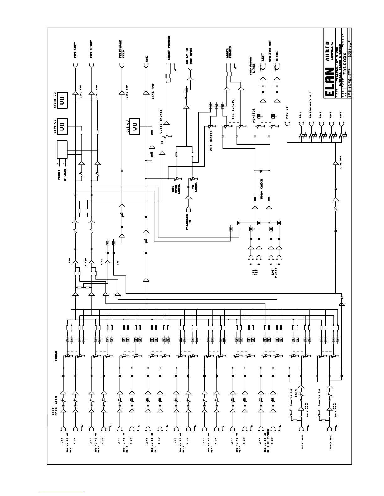
The Falcon-10 is the “Entry Level” Mixer in the Elan Audio range, and is provided with 8 Stereo High
Level, and 2 Mono Microphone Level Input Channels
Each Input Channel is provided with 3 Switches, OFF, ON, CUE and a Linear Slide Fader
The Switches are illuminated by LED’s, and give “Clickless” control of Channel OFF, Channel ON and
Channel to CUE with the Fader controlling the audio level to the Program Output or the Cue System
The Switches are Interlocked electronically with only one active at a time allowing switching in any
sequence, such as switching from CUE direct to ON without having to go through the OFF position
Input Channels 1 to 7 are identical Stereo High Level Inputs
Input Channel 8 can be used as either a Stereo High Level Input, or as a Mono Telephone Input
An external Telephone Hybrid Unit, not supplied with the Falcon-10 Mixer, must be installed between the
Telephone Line and High Level Input 8 in order to record or broadcast telephone conversations
A basic description of Telephone Systems Connection and Operation follows later in this
Input 9 is the Guest Microphone Input, and input 10, the Announcer Microphone Input
An Interlocking 5 Position Stereo Switch (A) see page 8, not wired as supplied, is located to the Left in
the riser panel and intended for a possible input line expansion to High Level Input 1
The FLCN-RC Remote Start-Stop Module, supplied to order as an option for the Falcon-10, provides
remote Start and Stop functions via the Channel On and Off Switches to Professional Source Equipment
and makes operation of the mixer easier
We assume here that Gain Settings of all input channels has been adjusted correctly by the station
technician to match the levels of source equipment such as CD Players, Microphones etc connected to it,
and also assume the mixer has been fully installed with a suitable Monitor Amplifier, Monitor Speakers,
Headphones, Off-Air Monitor Receiver etc and ready for operation
First a brief discussion on Audio Levels and Audio Metering
All On-Air Audio Mixers produced by Elan Audio are designed to be forgiving and easy to use and are in
themselves quite tolerant of incorrect Audio Levels
Nonetheless, it is very important, in order to obtain best possible Transmitted Sound Quality from the
station that any audio equipment including the On-Air Mixer be operated at its correct audio levels
Operating with Correct Audio Levels are particularly important to the station Audio Processor that will
attempt to keep modulation levels correct
2
It may in the process “Suck Up Noise” on low audio levels, and can on excessively high audio levels
produce Distortion, unpleasant Over Compressed Squashed Sound and “Pumping Effects”
Reading Audio Level Meters, and operating equipment at its correct levels is not difficult, but does require
some Basic Skill and Attention, as well as an appreciation of Audio Quality
Unfortunately, a bewildering number of different types and styles of Audio Level Indicators are found on
Domestic, Semi Professional and “On-Screen” Meters on Computer based Audio Equipment
Some make some sort of sense and are quite good if you understand how to read them, while others are
completely useless, including mechanical meters provided with VU Scales that are Virtually Useless
For Broadcasting in Australia, there are only two recognised Audio Metering Standards
One is the IEC Type II Peak Programme Meters, identical ballistics, available with two different scales
IEC Type II A, BBC Type, scaled 1 to 7, and the IEC Type II B scaled –12 to +12
The other, and most common type is the VU Meter
A “Real VU Meter” conforming to the ANSI Standard, whether a mechanical type or a column of LED’s is
a meaningful Volume Indicator, and very pleasant to use while as mentioned above, spurious Audio Level
Meters with VU Scaling are Virtually Useless
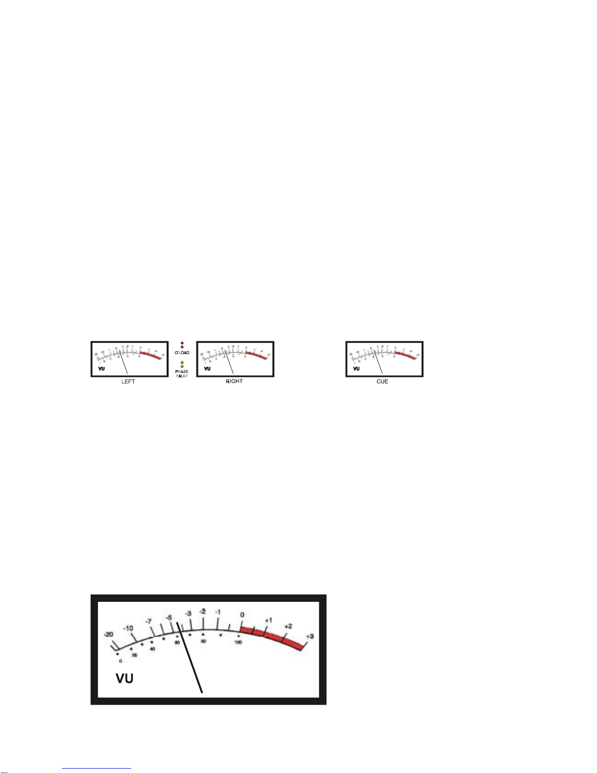
The Falcon-10 is provided with three mechanical VU Meters, an LED Overload indicator, and a Phase
Fault Indicator (B)
Two of the VU Meters are arranged to indicate Left and Right Channel Audio Levels, the third VU Meter is
connected to the Cue Channel allowing the operator to set the Channel Fader to correct level before
switching the channel To-Air
The LED Overload Indicator is shared between Left and Right Channels and operates by sensing Peak
Levels, and set to Flash at a level 10 dB above 0 VU to indicate whenever the Permitted Maximum Level
of the system is exceeded, and possible overload occurring making the station sound bad
The Phase Fault Indicator is basically a Mono Compatibility check facility and is complicated to explain
It will flash whenever the Sum of L+R is less than L-R and it is perfectly normal for this to flash briefly
when playing normal Stereo Music material
If illuminated most of the time, a Phase Reversal Problem on the recorded material being played To-Air is
indicated and can be verified by pressing the Mono Check Button, described further under Monitoring
The combination of VU Meters and the Overload LED Indicator makes it easy to operate the Falcon-10
Mixer at the correct Audio Levels

3
As a general guide for Microphones, adjust Channel Gain when speaking into the Microphone at a
Normal Voice Level, to indicate between – 3 VU and – 4 VU, and allow the Overload Indicator to flash
briefly 2 to 3 times a minute
For Recorded Music, “Best Level” varies somewhat, depending on the type of music being broadcast
Modern “Pop” Music is generally recorded to have a very limited “Dynamic Range”
Adjust Channel Gain to peak between 0 VU and + 1 VU, and allow the Overload Indicator to flash briefly
2 to 3 times a minute
Country, Jazz and Blues is recorded with a reasonably wide “Dynamic Range”
Adjust Channel Gain to indicate around –3 dB on normal passages, and peak to 0 VU, and allow the
Overload Indicator to flash briefly 2 to 3 times a minute
Classical Music is recorded with a very wide “Dynamic Range”
It is very difficult to give definite directions in regard to Audio Levels for Classical Music as correct level
can range from – 15 or - 20 VU on quiet passages to 0 VU or maybe even + 2 VU on loud passages
As an example, the Harp produces very sharp peaks that can flash the Overload Indicator with the VU
Meter reading maybe – 15 VU
As a general rule, allow the Overload Indicator to flash briefly 1 or 2 times a minute on loud passages
Operating ON-OFF-CUE switches and Faders
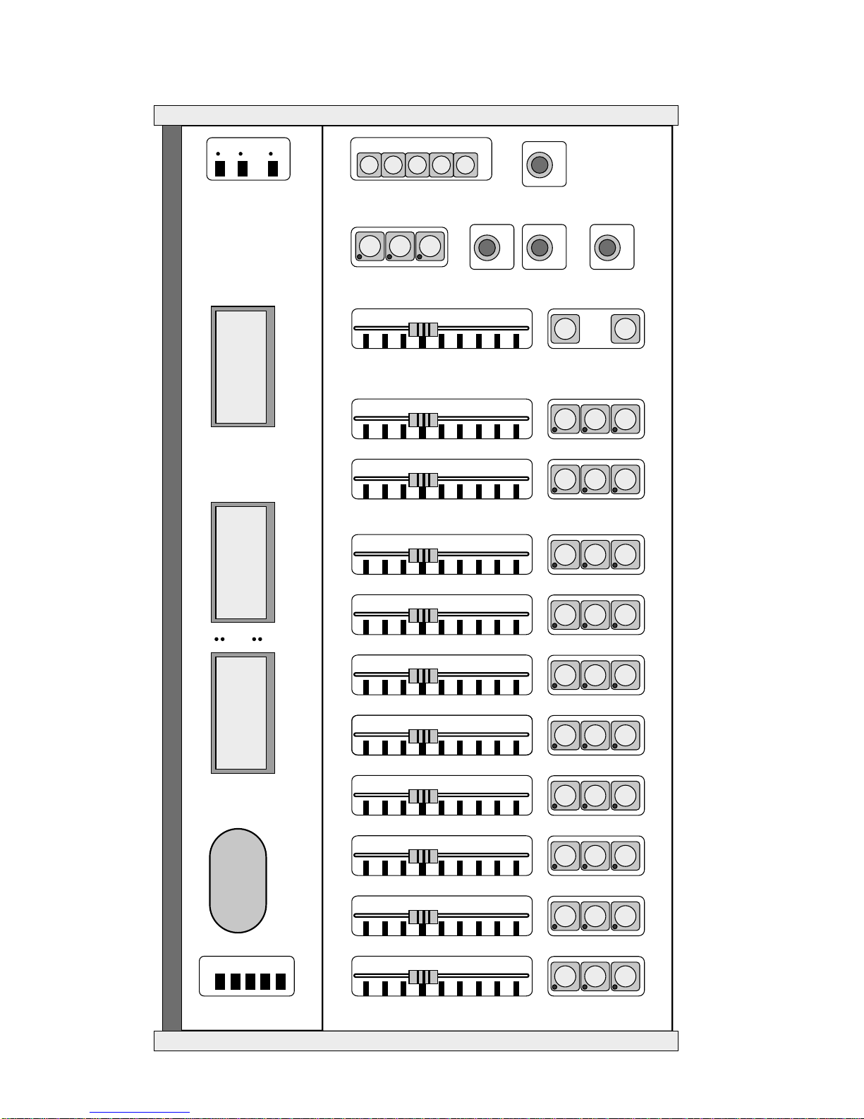
Each Input Channel on the Falcon-10 Mixer is provided with a Slide Fader for Audio Level control (C1),
and three Illuminated Push Button Switches (C2) controlling Channel OFF, Channel to CUE, and
Channel ON to the Mixer Output via the Mixing Buses
If the optional FLCN-RC Module is fitted, remote Start and Stop of Professional CD Players, other
Professional Source equipment and Control of a Telephone Hybrid Unit etc is provided by the Channel
ON and OFF Buttons making operation of the Falcon-10 extremely easy
If the FLCN-RC Module is not fitted, Start and Stop control of the Source Equipment, must be done
manually by the operator
The functions of the Channel Control Buttons are as follows
OFF, the Channel is switched OFF with the LED in button illuminated, indicating Channel OFF
CUE, the Channel is switched to CUE with the LED in button illuminated, indicating Channel to CUE
For a Stereo High Level Input Channel, audio is fed to the CUE VU Meter, the CUE Speaker, and to
one side of the Operators or Announcers Headphone
For a Microphone Channel, audio is fed to the CUE VU Meter and to one side of the Operators or
Announcers Headphone, With a Microphone Channel to CUE, the CUE and Monitor Speakers are Muted
Level can be Pre-Set by moving the Fader to give correct level indication on the VU Meter, and also
allows the operator to listen to audio before switching this To-Air
ON, the Channel is switched on to the Mixer Output via the Mixing Buses
With a Microphone Channel switched ON, the CUE and Monitor Speakers are Muted, and a Relay
Contact closed to operate the Studio On-Air Light
High Level Input 8 if not used as the Telephone Channel Input operates identically to all other High Level
Inputs

4
Operation of High Level Input 8 when used as a Telephone Channel in conjunction with an external
Telephone Hybrid Unit is described later in this
Next are operational suggestions when operating the Falcon-10 On-Air as an Audio Mixer
FALCON-10 Operational Hints
High Level Inputs
All of the High Level Inputs are designed to accept Stereo Source Equipment, such as Record Players,
CD Players, Mini Disk, Cassette Decks, PC Based Playback Systems, Outside Broadcast Lines, Satellite
Feeds and etc
Each Input Channel is either switched OFF, Switched to CUE, or Switched ON with Audio Level being
controlled by the Fader
The purpose of the CUE facility is
•Listen to an Audio Source and adjust the Audio Level before switching the channel ON To-Air
•Check for contents, such as verifying that the track you are about to play is the one you want
•Cue a Record Player or Cassette Tape to the start of recorded material
•Listen Off-Air to an OB Line or Satellite Feed and switch Channel ON at the right moment
You can switch directly from CUE to channel ON and back again without going through OFF
Switching Input Channel ON To-Air
For Source Equipment, not provided with Remote Start
Ensure that Fader is set to correct position, Switch Channel ON, next, Start the Source Equipment
For Source Equipment, provided with Remote Start
Ensure that Fader is set to correct position, Switch Channel ON, Source Equipment Starts Automatically
For OB or Satellite Feeds
Leave channel in CUE, ensure Fader is in correct position, listen to the programme, Switch Channel ON
when wanted content starts
Suggestion for material with Soft Intro
Advance the Fader slightly to bring up the Soft Intro, back it off gently to correct level when intro finished
Microphone Channels
Designed to accept Guest and Announcers Microphones
Microphone Input Channels are either switched OFF, Switched to CUE, or Switched ON with Audio Level
being controlled by the Fader
The purpose of the CUE facility is
•To set the level of the Microphone Channel to be correct before Switching ON
•To ensure that the Microphone is actually functioning
•To ensure that the Microphone is not Popping or Picking Up Unwanted Noises
Comments and Suggestions
•Please take note of the Audio Levels for Microphones, discussed earlier in this
•The Voice Level and Technique for each Announcer differ, use CUE to get Correct Level
•Experiment with and Practise using different Microphone Techniques

5
•Voice Levels and Microphone Techniques of Guests are unpredictable, be on guard
•Foam Rubber Windsocks becomes a “Health-Hazard” fairly quickly, replace them frequently
•Use a “Pop Killer” to prevent Popping, a worthwhile investment
Monitoring
It is very important that the Presenter or Announcer Monitor the Station Off-Air in order to identify Audio
Quality or Transmission Problems, and take the necessary action to correct these
In order to perform this task properly, the following is needed
•A real Receiving Antenna, properly installed, not just a Piece of Wire
•A Professional Off-Air Monitor Receiver such as the Elan RMR-01
•A Quality Monitor Amplifier such as the Elan Audio RMA-01
•A Pair of Quality Loudspeakers such as the Energy C3, available form Elan Audio
•A Set of Quality Headphones, Minimum AKG K44 or better, available from Elan Audio
A Piece of Wire as an Antenna, feeding a Cast Off Hi-Fi Tuner, or “Ghetto Blaster”, is simply not good
enough as an Off-Air Receiver, nor is the average sort of Stereo Amplifier and Loudspeakers you can
pick up from your local Op-Shop for $ 20.00c, or even worse, a pair of Computer Speakers
Sure, it will work, but will in all likelihood not allow you to notice subtle Audio Quality or Transmission
Problems
The same goes for Headphones, the $ 2.00c ones from King-Kong are simply not good enough
FM Radio Broadcasting should sound as good listening Off-Air on the Studio Monitor System, as your
favourite CD played at home on a Quality Stereo System
Having gotten this across, we will proceed to discuss the Monitor Facilities provided on the Falcon-10
Monitor Selection (D)
Three Interlocking Push Buttons, select the Monitor Source, Off-Air, EXT and PGM
•Off-Air must be selected as the Monitor Source when Broadcasting To-Air
•Extension is a Spare Monitor Input and may be ignored or used to monitor an external source
•Program is the Output of the Mixer and used when recording etc, not when broadcasting To-Air
Monitor Fader (E)
Controls the Volume of the Studio Loudspeaker Monitor System
Please note that the Studio Loudspeaker will Mute whenever a Microphone is switched ON or to CUE
Mono Check (E1)
Push Button will combine Left and Right Monitor Channels to become a Mono Signal, allowing the
operator to check for Mono Compatibility of the Transmitted Audio
If the Phase Fault Light is on most of the time, and the Monitor Speakers or Headphones sounds strange,
Press the Mono Check Button
If the Bass or Vocals almost disappears you have a Phase or Mono Compatibility problem that you
unfortunately cannot do anything about, and it sounds very bad on Mono Receivers
Phase and Mono Compatibility Problems are unfortunately not unusual on Amateur Recordings and
cheap CD Compilations

6
Mute (E2)
Push Button will momentarily Mute the Monitor Speakers, handy not to disturb the Monitor Volume
Setting if someone walks into the studio
Announcers Headphones
Normally, the Announcers Headphones receive the Selected Monitor feed, in Stereo
When CUE is selected on any Input Channel, Left Channel Headphone Monitor Feed is interrupted, and
replaced with the selected CUE source allowing the Announcer to use the CUE System with Microphones
switched ON
A facility also exist to switch Talkback Audio into the Left Channel of the Announcers Headphone using
PTT contacts, allowing Producer Talkback to Announcer with Microphones switched ON
CUE Phone Level Control (F)
Adjusts the Volume of the CUE channel into the Left Channel of the Announcers Headphone
PGM Phones Level Control (G)
Adjusts the Volume of the selected Monitor Source into the Announcers Headphone
CUE Speaker Level Control (H)
Adjusts the Volume of the CUE Speaker
Please note that the CUE Loudspeaker will Mute whenever a Microphone is switched ON or to CUE
Other Features on the Falcon-10
Talkback Buttons (I1)
Allows Talkback from the Announcers Microphone to 5 other locations provided with Talkback Facilities
such as other studios, reception area, house PA etc
Just ignore if such facilities are not provided in your station
Talkback Level Control (I2)
Adjusts Talkback Level into your CUE Speaker from other studios etc if provided
On-Air, On-Delay and Dump Switches (J)
These Switches are provided in the Falcon-10 to control external equipment, and as supplied, not wired
to anything
On-Air Switch is intended to control an external Delegation Switcher such as the Elan Audio RDS-02
Delay and Dump Switches are intended to control an external Telephone Delay System, such as the
Elan Audio RTD-01
Just ignore if such facilities are not provided in your station
Guest Headphone Feed
Guest Headphones receive Mixer Programme Output in Mono with Level Control on an internal Trimpot
The Headphone feed is accessed on internal screw terminals

7
Telephone Talkback
A Telephone Hybrid is a very complex 2 Wire to 4 Wire Converter
It connects via 2 Wires to the General Telephone System, and is provided with a Line Output, (2 Wires) to
feed into HL-8 on the Mixer, and a Line Input, (2 Wires) to be fed from the Mixer Telephone Feed
High Level Input Channel 8 on the Falcon-10, is provided with a special Mix Minus facility required for use
as the Telephone Talkback
The Telephone Hybrid can be controlled from the Mixer if fitted with the FLCN-RC Module
If the FLCN-RC Module is not fitted in the mixer, the Telephone Hybrid must be controlled by it’s front
panel mounted control switches
Operation is a bit more complex than the ordinary High Level or Microphone Inputs
Here goes
Normally, a Telephone Hybrid Unit is provided with a Telephone Line Loop Through, allowing a Normal
Telephone to be connected across the telephone line, and be used as a normal telephone
To Receive a Call and converse with the caller
Switch HL Input 8 to CUE, and take the call on the Telephone Hybrid, if not controlled by the FLCN-RC
You will now hear the caller through the Cue Speaker, and the Left Headphone Call, and the Caller will
hear you through the Announcers Microphone
The caller will not go To-Air, no need to switch the Announcers Microphone ON or to CUE
To take the call To-Air
Switch the Announcers Microphone ON, Fader must be in the normal position, then switch the Telephone
Hybrid from CUE to ON, the caller is now On-Air
The caller will hear the Announcer, and any other Input Channel that is switched ON, including the Guest
Microphone, but not self due to the Mix Minus facility
To make a call
Use the normal telephone to dial out, when ringing, transfer the call to the Telephone Hybrid, and take the
call to CUE
When the call is established, you can take the call To-Air
CUE
CUE
CUE
CUE CUE CUE CUE CUE CUE
OFF
OFF
OFF
OFF OFF OFF OFF OFF OFF
ON
ON
ON
ON ON ON ON ON ON
HL-4HL-4
HL-3
HL-2
HL-1 HL-5 HL-6 HL-7 HL-8 GUEST MIC
GUEST MIC ANNCR MICANNCR MIC MONITOR
MUTE
MONO
CHECK
TALKBACK
TB-1
TB-2
TB-3
TB-4
TB-5
CUE PHONES
CUE PHONES
PGM PHONESPGM PHONES TALKBACKTALKBACK
CUE SPEAKERCUE SPEAKER
+3 +3 +3
+3
+3
+3
+3
+3
+3
+3
+3
+2 +2 +2
+2
+2
+2
+2
+2
+2
+2
+2
+1 +1 +1
+1
+1
+1
+1
+1
+1
+1
+1
000
0
0
0
0
0
0
0
0
-1 -1 -1
-1
-1
-1
-1
-1
-1
-1
-1
-2 -2 -2
-2
-2
-2
-2
-2
-2
-2
-2
-3 -3 -3
-3
-3
-3
-3
-3
-3
-3
-3
-4 -4 -4
-4
-4
-4
-4
-4
-4
-4
-4
-5 -5 -5
-5
-5
-5
-5
-5
-5
-5
-5
ON-AIR
ON-DELAY
ON-DELAY
DUMP
ELAN
Audio
" FALCON ""FALCON "
Professional Audio MixerProfessional Audio Mixer
HL SELHL SEL
1
2
3
4
5
O'LOAD
PHASE
OFF
AIR
OFF
AIR
EXT
PGM
MONITOR
SELECT
MONITOR
SELECT
VU VU VU
LEFT RIGHT CUE
ELAN "Falcon-10" On Air MixerELAN "Falcon-10" On Air Mixer Physical Dimensions
W 640mm D 360mm H 145mm
Physical Dimensions
W640mm D360mm H145mm