ELAN AUDIO M Series User manual

www.elanhomesystems.com
2428 Palumbo Drive • Lexington, KY 40509
1.877.289.3526
SPEAKER INSTALLATION
MANUAL
Limited Lifetime Warranty
ELAN HOME SYSTEMS, L.L.C. ("ELAN") warrants to the original retail purchaser only that
all M Series speakers and speaker brackets will be free from defects in materials and
workmanship, provided that the product was purchased from an authorized ELAN Home
Systems Dealer.
If the above purchaser discovers such item was not as warranted above and promptly
notifies ELAN writing, ELAN shall repair or replace the items at the company’s option.
This warranty shall not apply (a) to equipment not manufactured by ELAN, (b) to equipment
which shall have been installed by other than an authorized ELAN installer, (c) to installed
equipment which is not installed to ELAN’s specifications, (d) to equipment which shall
have been repaired or altered by others than ELAN, (e) to equipment which shall have
been subjected to negligence, accident, or damage by circumstances beyond ELAN’s
control, including, but not limited to, lightning, flood, electrical surge, tornado, earthquake,
or any other catastrophic events beyond ELAN’s control, or to improper operation,
maintenance or storage, or to other than normal use of service. With respect to equipment
sold by, but not manufactured by ELAN, the warranty obligations of ELAN shall in all
respects conform and be limited to the warranty actually extended to ELAN by its supplier.
The foregoing warranties do not cover reimbursement for labor, transportation, removal,
installation, or other expenses which may be incurred in connection with repair or
replacement.
Except as may be expressly provided and authorized in writing by ELAN, ELAN shall not
be subject to any other obligations or liabilities whatsoever with respect to equipment
manufactured by ELAN or services rendered by ELAN.
THE FOREGOING WARRANTIES ARE EXCLUSIVE AND IN LIEU OF ALL OTHER
EXPRESSED AND IMPLIED WARRANTIES EXCEPT WARRANTIES OF TITLE,
INCLUDING BUT NOT LIMITED TO IMPLIED WARRANTIES OF MERCHANTABILITY
AND FITNESS FOR A PARTICULAR PURPOSE.
M Series_Manual_June2003.qxd 6/10/03 9:08 AM Page 2

© ELAN Home Systems 2003 • All rights reserved. 06/2003
ELAN HOME SYSTEMS
INSTALLATION MANUAL
14
M SERIES INSTALLATION GUIDELINES
5.25" Model Cutout Dimensions Dimensions w/ Frame Total Depth
Depth
ME525D 6-13/16" (173mm) diameter 8" (203mm) diameter 4-1/8" (104mm)
ME525C 6-13/16" (173mm) diameter 8" (203mm) diameter 4-1/8" (104mm)
ME525W 6-1/8" x 10-1/4" (156x260mm) 7-3/8" x 11-9/16" (187x294mm) 3-3/4" (94mm)
MM525C 6-13/15" (173mm) diameter 8" (203mm) diameter 4-5/8" (116mm)
MM525W 6-1/8" x 10-1/4" (156x260mm) 7-3/8" x 11-9/16" (187x294mm) 4-3/4" (94mm)
MP525W 6-1/8" x 10-1/4" (156x260mm) 7-3/8" x 11-9/16" (187x294mm) 3-3/4" (94mm)
6.50" Model Cutout Dimensions Dimensions w/ Frame Total Depth
MC650C 8-1/16" (205mm) diameter 9-1/4" (235mm) diameter 3-5/8" (92mm)
MC650W 7-1/8" x 12-1/4" (181 x 311mm) 8-1/4" x 13-1/2" (210 x 343mm) 3-5/16" (83mm)
ME650C 8-1/16" (205mm) diameter 9-1/4" (235mm) diameter 4-1/4" (107mm)
ME650W 7-1/8" x 12-1/4" (181 x 311mm) 8-1/4" x 13-1/2" (210 x 343mm) 3-3/4" (94mm)
MM650C 8-1/16" (205mm) diameter 9-1/4" (235mm) diameter 4-1/2 (111.5mm)
MM650W 7-1/8" x 12-1/4" (181 x 311mm) 8-1/4" x 13-1/2" (210 x 343mm) 3-3/4" (94mm)
MM650D 8-1/16" (205mm) diameter 9-1/4" (235mm) diameter 4-1/2" (111.5mm)
MP650 C 8-1/16" (205mm) diameter 9-1/4" (235mm) diameter 4-13/16" (122mm)
MP650 W 7-1/8" x 12-1/4" (181 x 311mm) 8-1/4" x 13-1/2" (210 x 343mm) 3-13/16" (96mm)
8" Model Cutout Dimensions Dimensions w/ Frame Total Depth
ME800C 9-3/4" (248mm) diameter 11" (278mm) diameter 4-13/16" (122mm)
MM800C 9-3/4" (248mm) diameter 11" (278mm) diameter 4-13/16" (122mm)
MM800W 8-5/8" x 15-3/16" (219 x 386mm) 9-7/8" x 16-1/2" (251 x 419mm) 4" (102mm)
MP800C 9-3/4" (248mm) diameter 11" (278mm) diameter 5" (127mm)
MP800W 8-5/8" x 15-3/16" (219 x 386mm) 9-7/8" x 16-1/2" (251 x 419mm) 4" (101mm)
MP800S 8-5/8" x 15-3/16" (219 x 386mm) 9-7/8" x 16-1/2" (251 x 419mm) 4" (101mm)
MP800D 9-3/4" (248mm) diameter 11" (278mm) diameter 5-1/2" (139mm)
ELAN HOME SYSTEMS INSTALLATION MANUAL
© ELAN Home Systems 2003 • All rights reserved. 06/2003
1
Introduction
M Series by ELAN: An In-Wall Speaker Line of Distinction . . . . . . . . . . . . . . . . .2
Installation Overview
About the M Series "Mounting Clamp" Design . . . . . . . . . . . . . . . . . . . . . . . . . .3
Removable Baffles . . . . . . . . . . . . . . . . . . . . . . . . . . . . . . . . . . . . . . . . . . . . . . .3
Painting the Speakers . . . . . . . . . . . . . . . . . . . . . . . . . . . . . . . . . . . . . . . . . . . .3
Installation Procedures
General Information . . . . . . . . . . . . . . . . . . . . . . . . . . . . . . . . . . . . . . . . . . . . .3
Cutting Speaker Openings . . . . . . . . . . . . . . . . . . . . . . . . . . . . . . . . . . . . . . . . .4
In-Ceiling Speaker Installation . . . . . . . . . . . . . . . . . . . . . . . . . . . . . . . . . . . .4, 5
In-Wall Speaker Installation . . . . . . . . . . . . . . . . . . . . . . . . . . . . . . . . . . . . . . . .5
Frame Only Installations . . . . . . . . . . . . . . . . . . . . . . . . . . . . . . . . . . . . . . . .6, 7
Re-Installing Baffles . . . . . . . . . . . . . . . . . . . . . . . . . . . . . . . . . . . . . . . . . . . . . .8
Installing the IR Tube . . . . . . . . . . . . . . . . . . . . . . . . . . . . . . . . . . . . . . . . . . . . .9
Dual-Channel and Subwoofer Speaker Applications
Dual-Channel and Subwoofer Speakers . . . . . . . . . . . . . . . . . . . . . . . . . . . . . .10
Application Diagrams . . . . . . . . . . . . . . . . . . . . . . . . . . . . . . . . . . . . . . . . .11-12
M Series Specifications
M Series Cutout Dimensions . . . . . . . . . . . . . . . . . . . . . . . . . . . . . . . . . . . . . .13
M Series Specifications and Driver Components . . . . . . . . . . . . . . . . . . . . . . . .14
Lifetime Warranty . . . . . . . . . . . . . . . . . . . . . . . . . . . . . . . . . . . . . . . . . . .Back Cover
TABLE OF CONTENTS
M Series_Manual_June2003.qxd 6/10/03 9:08 AM Page 4

ELAN HOME SYSTEMS INSTALLATION MANUAL
© ELAN Home Systems 2003 • All rights reserved. 06/2003
13
M SERIES SPECIFICATIONS AND DRIVER COMPONENTS
The ELAN M Series In-Wall/In-Ceiling Loudspeaker line is constructed using the finest
materials available to provide a lifetime of listening enjoyment.
Specs MC (Level 1) ME (Level 2) MM (Level 3) MP (Level 4)
Tweeter PEI Silk Silk Aluminum and
Material Magnesium
Composite
Woofer Cone Polypropylene Mineral Filled Injection Molded Woven Glass
Polypropylene Mica Fiber
Woofer Inverted Butyl Inverted Butyl Inverted Butyl Inverted Butyl
Surround
Woofer Stamped Stamped Stamped Glass Fiber
Basket Composite
Crossover 6dB/octave 6dB/octave 12dB/octave Linkwitz/Riley
Response
Crossover None None Treble Treble/Bass
Switches
Interconnect 20AWG 20AWG 18AWG 16AWG
Wire
Input Spring Spring Gold-Plated Gold-Plated
Connectors Terminals Terminals Push Terminals Push Terminals
Hardware Black Oxide Black Oxide Stainless Steel Stainless Steel
Nominal 8 Ohms 8 Ohms 8 Ohms 8 Ohms
Impedance
Sensitivity 87dB 87-90dB 88-91dB 89-93dB
Range (1W/1Meter) (1W/1Meter) (1W/1Meter) (1W/1Meter)
Power 5.25"= 5 - 40W 5.25"= 5 - 50W 5.25"= 5 - 60W
Handling 6.50"= 5-50W 6.50"= 5 - 65W 6.50"= 5 - 75W 6.50"= 5 - 85W
8"= 5 - 80W 8"= 5 - 90W 8"= 5 - 100W
© ELAN Home Systems 2003 • All rights reserved. 06/2003 2
ELAN HOME SYSTEMS
INSTALLATION MANUAL
The ELAN M Series is a multi-tiered speaker
offering that achieves a new level of design
flexibility and acoustical performance.
True quality begins with a discriminating eye
toward the goal. The goal? To deliver a line
of in-wall and in-ceiling speakers with
superior performance at all price levels.
The process began by assessing every
major name brand in-wall speaker for
performance, price, aesthetics and
attention to detail. From there it went to
the lab–– listening, evaluating, analyzing,
comparing, debating, formulating,
reformulating and defining.
We hired world-class acoustical
engineers to refine our conclusions. We
summoned expert dealers to test the
design decisions, assortment and product
attributes. We then selected the finest
materials at each cost level to create a
consistent offering. The materials were
carefully tested and voiced against the
nearest competitive speaker to arrive at the
best performance against every model
offered in each class.
The result: speakers second to none in
every class from basic to premium grade.
In fact, the M Series are the top performers
in each cost class. Better sound, better
looks, and better quality at a given price.
DISCERNING FEATURES
Styling Perfection––Narrower flat-profiles,
sharp-radius frames and tall aspect ratios
make for a sleek, slim appearance on the
wall. A fine-mesh grille finish adds to the
elegant look of the M Series products.
Acoustical Mastering––Balance across the
full range of the musical spectrum requires
a sophisticated selection of the right woofer
cones, surrounds, tweeters, crossover
components and baffle construction for each
system. Most importantly, each crossover
has been "voiced" to provide the best
performance for the materials deployed.
Installation Provisions––Getting the speaker
in the wall solidly and efficiently is
beneficial to its end use. The ability to
mount these designs with or without
baffles, and the flexible stud mounting
flanges makes installation a snap in the
most difficult locations. The multi-legged
clamp system provides the best means for
eliminating undesirable vibration common
with other speaker alternatives.
A Family of Performers––When multiple
speakers from other manufacturers were
tested, the range of performance fell off
considerably between models. No one
company exceeded average performance
with all models in the given class. M Series
provides above average performance with
all models - with no under performers in
the entire lineup.
Listen with Confidence––All M Series
speakers come with a Limited Lifetime
Warranty.
Enjoy Your Choice––You are about to
experience music reproduction few expect
from an in-wall speaker. Sit back and
listen, and savor the resounding quality
that your new ELAN speakers deliver. We
are pleased to be able to provide you with
many pleasurable moments for years to
come. Thank you for your selection of
M Series––and enjoy the music.
M SERIES BY ELAN:
ANIN-WALL SPEAKER LINE OF DISTINCTION
M Series_Manual_June2003.qxd 6/10/03 9:08 AM Page 6

© ELAN Home Systems 2003 • All rights reserved. 06/2003 12
ELAN HOME SYSTEMS
INSTALLATION MANUAL
FIGURE 14 Using the dual voice coils of the ELAN MP800S passive sub to enhance the low
frequency performance of smaller in-wall (or in-ceiling) satellite speakers.
FIGURE 15 Using two ELAN MP800S subs to substantially increase the low frequency
performance of smaller in-wall (or in-ceiling) satellite speakers
ELAN HOME SYSTEMS INSTALLATION MANUAL
© ELAN Home Systems 2003 • All rights reserved. 06/2003
3
ABOUT THE M SERIES
MOUNTING CLAMP DESIGN
All models in the ELAN M Series speaker
line feature rigid, heavy-duty mounting
clamps that ensure a quick, secure,
vibration-free installation in walls from
1/2" to 1 1/2" in thickness.
The ceiling models and 5.25" In-Walls
have four mounting clamps each. The 6.5"
and 8" In-Wall models have six mounting
clamps.
REMOVABLE BAFFLES
(ME, MM AND MP MODELS ONLY)*
M Series’ removable baffle assemblies give
you important job-site options. With only
a frame and grille installed, there’s no
expensive baffle left unguarded at the job
site––simply install it when the interior is
complete. Removable baffles also allow
you to replace or upgrade speakers
without having to remove or re-paint the
frame and grille.
*NOTE: Mounting ceiling speaker
frames without a baffle requires
the use of M Series New
Construction Brackets. In-wall
frames would also require the use
of M Series New Construction
Brackets unless the frame is being
mounted directly to a stud. (see
Direct-To-Stud Mounting, Page 7).
DAMPING THE WALL CAVITY
Damping the wall/ceiling cavity behind the
speakers by loosely filling it with fire-rated
fiberglass insulation can enhance the per-
formance of your M Series speakers and
reduce unwanted transmission of sound
into adjacent rooms.
PAINTING THE SPEAKERS
All ELAN M SERIES speakers can be
finished to match any room décor. Their
white, textured frames and no-rust
aluminum grilles readily accept most
water-based interior latex and spray enamels.
We recommend the grille and frame be
painted separately. To aid in frame
painting, we’ve included a plastic paint
shield that will protect the speaker baffle.
Painting Tips:
1. If not using spray paint, we recommend
that the paint be thinned to prevent
clogging the speaker grille perforations.
2. When painting, several light coats will
yield the best results.
As the installation of flush-mount speakers
requires cutting into walls where high-
voltage wiring, pipes and duct work may
be present, installation should be
performed by experienced and trained
professionals only.
NOTES:
•Check for Obstructions––Before cutting
holes in any existing wall or ceiling
surface, the cavity behind each speaker’s
installation location MUST be probed
for obstructions. Make sure to probe
both speaker locations in the room to
ensure that symmetrical placement is
feasible.
INSTALLATION OVERVIEW
INSTALLATION
PROCEDURES
M Series_Manual_June2003.qxd 6/10/03 9:08 AM Page 8

ELAN HOME SYSTEMS INSTALLATION MANUAL
© ELAN Home Systems 2003 • All rights reserved. 06/2003
11
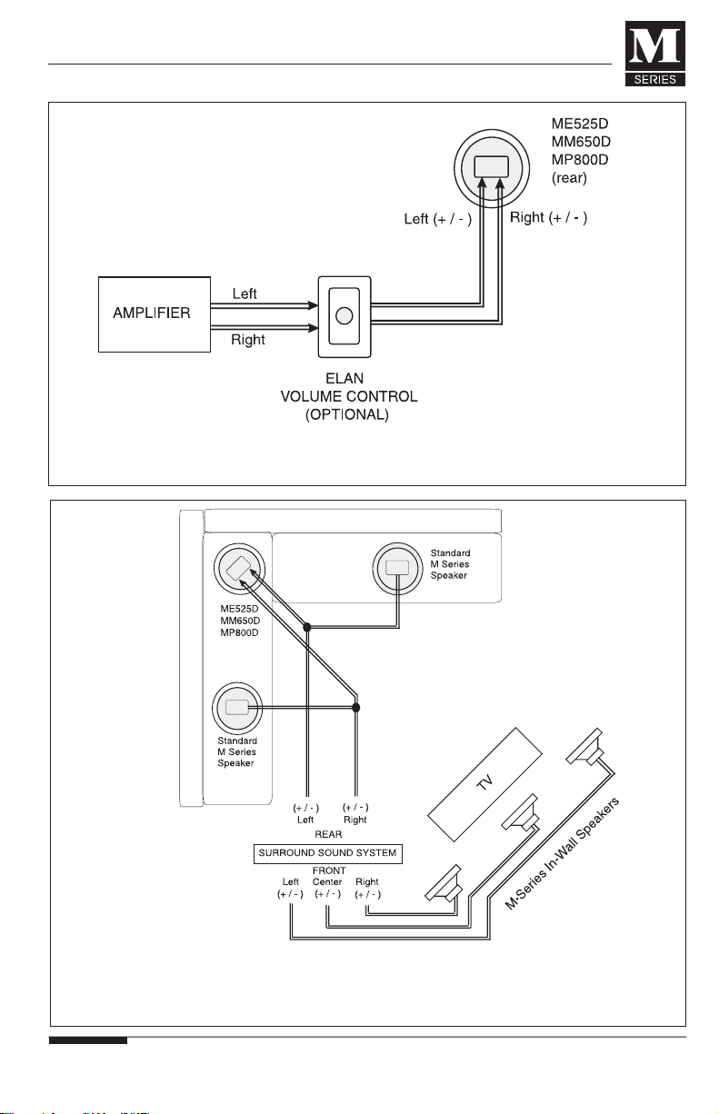
FIGURE 12 Standard wiring diagram for an ELAN M Series Dual Channel Speaker. Notice
that all four conductors (L+,L-,R+, R-) are run to the single speaker’s installation location.
FIGURE 13 Paralleling the rear outputs of a Surround Sound System to drive a pair of
in-ceiling speakers and an ELAN M Series Dual Channel Speaker to adequately cover an “L”
shaped seating area.
NOTE: Rear outputs must be able to drive a four Ohm speaker load.
© ELAN Home Systems 2003 • All rights reserved. 06/2003 4
ELAN HOME SYSTEMS
INSTALLATION MANUAL
•Always maintain proper polarity when
wiring speakers. Failure to do so will
result in poor stereo imaging and a
decrease in base response
•ELAN M SERIES speakers are factory
balanced for optimum performance
with the EQ switches in the 0 dB
position. + or – 3 dB adjustment is
provided to accommodate room
acoustics and personal taste. (MM
and MP models only)
CUTTING SPEAKER OPENINGS
IN FINISHED WALLS
1. Use a stud finder to locate the studs
around the intended speaker place-
ment. NOTE: A stud-finding device
MAY NOT detect pipes, wiring, or
other obstructions located behind the
drywall.
2. Use the inside portion of the speaker
cutout template to confirm the speaker
placements.
3. Remove templates and drill or carefully
poke a pilot hole in both locations. A
bent piece of wire or a coat hanger
may be use to probe
the stud bay for
obstructions. If you
experience resistance
of any kind–– STOP! If
any obstructions are
detected, patch the
pilot holes and try
again in another loca-
tion.
4. Once you have
determined the cavity is
free from obstructions,
re-position the cutout
template and use a
pencil to lightly trace
the perimeter of the template. If
installing an In-Wall speaker, use a
level to accurately position the cutout
before you trace its outline.
5. Use a keyhole saw, drywall router, or
razor knife to cut the openings.
IMPORTANT NOTE: The slim design
of M SERIES speaker frame flanges
require that careful attention be paid
to not oversize the cut-out hole.
IN-CEILING SPEAKER
INSTALLATION:
Complete Assemblies (with or
without New Construction Brackets)
1. Remove speaker grille and set speaker
face down on cardboard.
2. Locate the speaker wire and pull
through the wall opening.
3. Connect the speaker wire. BE SURE
TO OBSERVE CORRECT POLARITY!
FIGURE 1
CAUTION: DO NOT DROP SPEAKER ON ITS
BACK. DAMAGE COULD RESULT TO
CROSSOVER COMPONENTS.
!
M Series_Manual_June2003.qxd 6/10/03 9:08 AM Page 10
The ELAN M Series Specialty Speaker line
was designed to provide custom installers
with performance- oriented solutions.
These speaker systems are intended to
maximize the performance of distributed
audio and home theater systems utilizing
ELAN M Series speakers
M SERIES DUAL-CHANNEL
SPEAKERS
ELAN’s MM650D, and MP800D models
feature dual tweeters, dual voice coil
woofers, and a total of four speaker-level
inputs (L+, L-, R+, R-). The ME525D
features a “whizzer cone” design to
provide installers with a cost effective
dual-channel solution.
These features enable the custom installer
to reproduce both channels (left and right)
of stereo program material with a single
speaker.
Dual-channel speakers are ideal for
bathrooms, large walk-in closets, hall
ways, foyers, laundry rooms, kitchens,
and other locations where space does not
permit the installation of a pair of
speakers. Dual-channel speakers are also
ideal when used in conjunction with a
standard pair of in-ceiling speakers to
reproduce the rear channels in a home
theater with an “L” shaped seating area
(FIGURE 13). NOTE: The rear channel
amplification must be able to drive a
4 Ohm speaker load.
M SERIES PASSIVE IN-WALL
SUBWOOFER
ELAN’s MP800S speaker features:
•An 8” carbon fiber woofer featuring
1.5” dual voice coils.
•Low and high-pass circuitry (with a
80Hz high-pass output to the satellite
speakers)
•Athree-position low-pass frequency
selector switch (80Hz,100Hz, and 120Hz)
•Four speaker-level inputs (L+, L-, R+, R-),
and four speaker level outputs
(L+, L-, R+, R-).
The MP800S is designed to enhance the
low frequency performance of any pair of
ELAN M Series in-wall or in-ceiling
speakers. See next two pages for wiring
options.
© ELAN Home Systems 2003 • All rights reserved. 06/2003 10
ELAN HOME SYSTEMS
INSTALLATION MANUAL
DUAL-CHANNEL AND SUBWOOFER
PRODUCT APPLICATIONS
MP800S MP800D MM650D ME525D
ELAN HOME SYSTEMS INSTALLATION MANUAL
© ELAN Home Systems 2003 • All rights reserved. 06/2003
5
4. Insert the speaker into the opening In
the ceiling and CAREFULLY tighten
each of the four clamping screws,
alternating diagonally between each
screw position to ensure proper fit
and finish. FIGURE 1, Page 4
5. Set the EQ switches (MM and MP
models only).
6. Replace the speaker grille.
IN-WALL SPEAKER INSTALLATION:
Complete Assemblies (with or
without New Construction Brackets)
1. Remove speaker grille.
2. Locate the speaker wire (and IR wire,
if applicable) and pull through the
wall opening.
3. Install ELAN IR Tube if applicable (see
Installing the ELAN IR Tube, Pages 8,9)
4. Connect the speaker wire. BE SURE
TO OBSERVE CORRECT POLARITY!
5. Insert the speaker into the opening In
the wall and CAREFULLY tighten each
of the clamping screws (four on all 5
1/4" models, six on all 6 1/2" and 8"
models), alternating diagonally
between each screw position to ensure
proper fit and finish. FIGURE 2
NOTE: Do not place insulation directly
behind the 8” in-wall woofer magnets
as they are 4” deep.
CAUTION: DO NOT OVER-TIGHTEN
THE SCREWS!
(see caution note on
this page)
6. Set the EQ switches (MM and MP
models only).
7. Replace the speaker grille.
CAUTION: DO NOT OVER-TIGHTEN
THE SCREWS!
If using a drill to tighten the
clamping screws, be sure to set the
torque setting very low. Setting the
drill’s torque too high may break the
mounting clamps, the wall surface,
and/or the speaker frame assembly.
!
FIGURE 2
!
M Series_Manual_June2003.qxd 6/10/03 9:08 AM Page 12

ELAN HOME SYSTEMS INSTALLATION MANUAL
© ELAN Home Systems 2003 • All rights reserved. 06/2003
9
5. Connect 12V, GND, and SIGNAL as
per IR Tube instructions.
6. Press the tube firmly in place, and
screw down until nearly flush with
front of baffle. FIGURE 11
FIGURE 10
FIGURE 11
NOTE: Due to the grill,
IR receiving range will be
reduced from 27 feet to
approximately 15 feet.
© ELAN Home Systems 2003 • All rights reserved. 06/2003 6
ELAN HOME SYSTEMS
INSTALLATION MANUAL
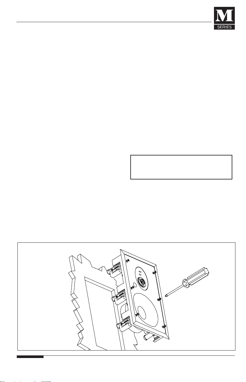
FRAME-ONLY INSTALLATION
(ME, MM & MP MODELS ONLY)
In-Ceiling Frame-Only Installation
(M SERIES New Construction Brackets
Required)
1. Remove the speaker grille and set
speaker face down on cardboard.
2. Remove the clamping screws (four)
from the speaker baffle, and the two
shipping screws on the back of the
speaker. FIGURE 3
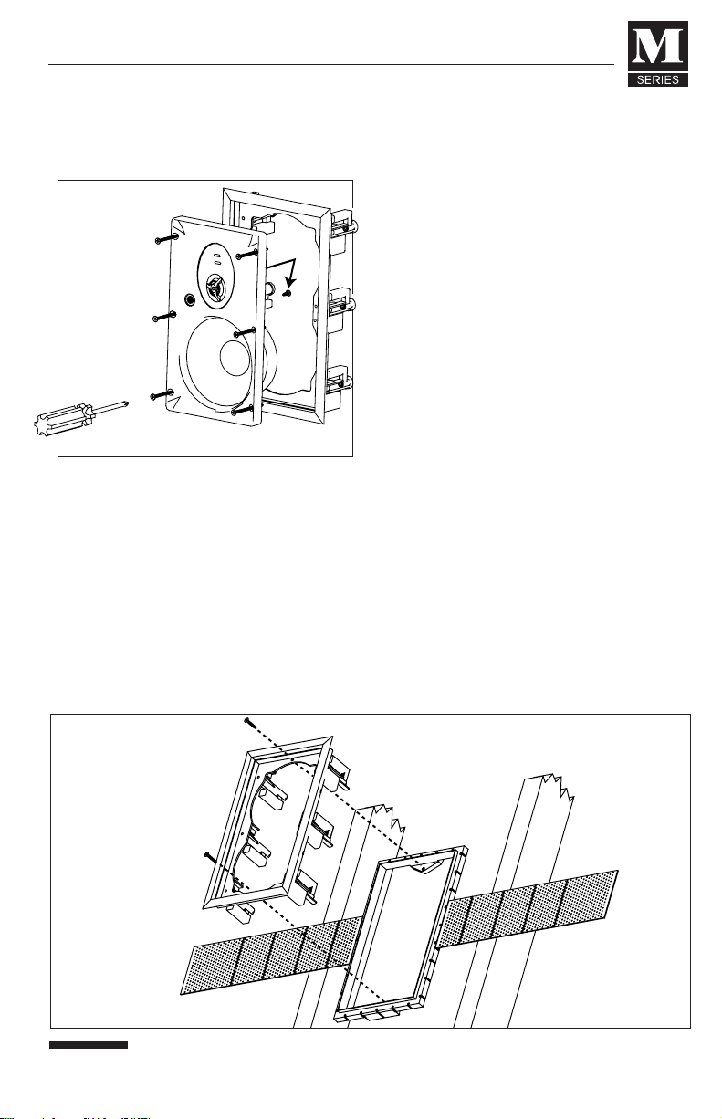
3. Remove speaker baffle and set aside.
NOTE: The Mounting Clamps remain
“captured” even though all screws are
removed. DO NOT remove the clamps.
4. The In-Ceiling Speaker Frame is ‘keyed’
for easy frame/bracket alignment. Insert
the speaker frame into the bracket and
rotate until frame ‘keys’ are aligned
with the bracket’s ‘slots’. FIGURE 3
5. With 2 bracket screws, secure the
frame to the bracket. Hand-tighten only.
NOTE: The rough-in bracket screws hold
the frame in place only. DO NOT OVER-
TIGHTEN as this may crack the Frame
and/or Bracket.
6. Replace the grille.
7. See "Re-installing The Ceiling Speaker
Baffle" on Page 8 when you are ready
to replace the baffle.
In-Wall Frame-Only Installation
In-Wall speaker frames can be mounted
into M Series New Construction Brackets
or directly to a stud.
Frame-to-Bracket Installation
1. Remove the speaker grille
2. Remove the clamping screws (four on
all 5 1/4" in-wall models, six on all 6
1/2" and 8" in-wall models) from the
speaker baffle, and the two shipping
screws on the back of the speaker.
FIGURE 5, NEXT PAGE
3. Remove speaker baffle and set aside.
FIGURE 3
FIGURE 4
FIGURE 4
CAUTION: DO NOT DROP SPEAKER ON ITS
BACK. DAMAGE COULD RESULT TO
CROSSOVER COMPONENTS.
!
M Series_Manual_June2003.qxd 6/10/03 9:08 AM Page 14
© ELAN Home Systems 2003 • All rights reserved. 06/2003 8
ELAN HOME SYSTEMS
INSTALLATION MANUAL
Re-Installing the Ceiling
Speaker Baffle
1. Return the baffle to the frame and
rotate until the ‘key’ lines up and the
baffle slides down into the frame.
2. Secure with the clamping screws (four).
FIGURE 8
Re-Installing the In-Wall
Speaker Baffle
1. Return the baffle to the frame and
secure with the clamping screws (four
on all 5 1/4" in-wall models, six on all
6 1/2" and 8" in-wall models). FIG 9
NOTE: If the Frame was mounted directly
to a stud, the mounting clamps adjacent to
the stud will only partially deploy when
the clamping screws are tightened.
DO NOT OVER-TIGHTEN.
INSTALLING THE ELAN
IR TUBE IN M SERIES
IN-WALL SPEAKERS
1. Locate IR knockout on face of speaker
baffle.
2. Place the speaker FACE-DOWN on its
carton
3. Using a 7/16” bit, drill the knockout
free. FIGURE 10
4. Trim away flash and rough edges.
FIGURE 7
FIGURE 8
FIGURE 9
ELAN HOME SYSTEMS INSTALLATION MANUAL
© ELAN Home Systems 2003 • All rights reserved. 06/2003
7
NOTE: The Mounting Clamps remain
‘captured’ even though all screws are
removed. DO NOT remove the clamps.
4. Insert the speaker frame into the brack-
et and secure it to the speaker bracket
with supplied rough-in bracket screws.
Hand-tighten only. FIGURE 6
NOTE: The rough-in bracket screws hold
the frame in place only. DO NOT
OVER-TIGHTEN as this may crack the
Frame and/or Bracket.
5. Replace the grille.
6. See "Re-installing the In-Wall Speaker
Baffle" on Page 8 when you are ready
to replace the baffle.
Direct-to-Stud Mounting
1. Remove the baffle as describe above
and set aside.
2. Place the speaker frame into the wall
opening and, using drywall screws,
secure it to the stud as shown in
FIGURE 7 on the following page.
NOTE: The screws should seat flush
against inside of the stud plate (next to
the clamp channels).Under-tightened
or poorly seated screws may result in
poor frame to baffle fit and unwanted
vibration or rattle.
a. Replace the grille.
b. See "Re-installing the In-Wall
Speaker Baffle" on Page 8 when
Ready to replace the baffle.
SHIPPING
SCREWS
FIGURE 5
FIGURE 6
M Series_Manual_June2003.qxd 6/10/03 9:08 AM Page 16

ELAN HOME SYSTEMS INSTALLATION MANUAL
© ELAN Home Systems 2003 • All rights reserved. 06/2003
9
5. Connect 12V, GND, and SIGNAL as
per IR Tube instructions.
6. Press the tube firmly in place, and
screw down until nearly flush with
front of baffle. FIGURE 11
FIGURE 10
FIGURE 11
NOTE: Due to the grill,
IR receiving range will be
reduced from 27 feet to
approximately 15 feet.
© ELAN Home Systems 2003 • All rights reserved. 06/2003 6
ELAN HOME SYSTEMS
INSTALLATION MANUAL
FRAME-ONLY INSTALLATION
(ME, MM & MP MODELS ONLY)
In-Ceiling Frame-Only Installation
(M SERIES New Construction Brackets
Required)
1. Remove the speaker grille and set
speaker face down on cardboard.
2. Remove the clamping screws (four)
from the speaker baffle, and the two
shipping screws on the back of the
speaker. FIGURE 3
3. Remove speaker baffle and set aside.
NOTE: The Mounting Clamps remain
“captured” even though all screws are
removed. DO NOT remove the clamps.
4. The In-Ceiling Speaker Frame is ‘keyed’
for easy frame/bracket alignment. Insert
the speaker frame into the bracket and
rotate until frame ‘keys’ are aligned
with the bracket’s ‘slots’. FIGURE 3
5. With 2 bracket screws, secure the
frame to the bracket. Hand-tighten only.
NOTE: The rough-in bracket screws hold
the frame in place only. DO NOT OVER-
TIGHTEN as this may crack the Frame
and/or Bracket.
6. Replace the grille.
7. See "Re-installing The Ceiling Speaker
Baffle" on Page 8 when you are ready
to replace the baffle.
In-Wall Frame-Only Installation
In-Wall speaker frames can be mounted
into M Series New Construction Brackets
or directly to a stud.
Frame-to-Bracket Installation
1. Remove the speaker grille
2. Remove the clamping screws (four on
all 5 1/4" in-wall models, six on all 6
1/2" and 8" in-wall models) from the
speaker baffle, and the two shipping
screws on the back of the speaker.
FIGURE 5, NEXT PAGE
3. Remove speaker baffle and set aside.
FIGURE 3
FIGURE 4
FIGURE 4
CAUTION: DO NOT DROP SPEAKER ON ITS
BACK. DAMAGE COULD RESULT TO
CROSSOVER COMPONENTS.
!
M Series_Manual_June2003.qxd 6/10/03 9:08 AM Page 14

The ELAN M Series Specialty Speaker line
was designed to provide custom installers
with performance- oriented solutions.
These speaker systems are intended to
maximize the performance of distributed
audio and home theater systems utilizing
ELAN M Series speakers
M SERIES DUAL-CHANNEL
SPEAKERS
ELAN’s MM650D, and MP800D models
feature dual tweeters, dual voice coil
woofers, and a total of four speaker-level
inputs (L+, L-, R+, R-). The ME525D
features a “whizzer cone” design to
provide installers with a cost effective
dual-channel solution.
These features enable the custom installer
to reproduce both channels (left and right)
of stereo program material with a single
speaker.
Dual-channel speakers are ideal for
bathrooms, large walk-in closets, hall
ways, foyers, laundry rooms, kitchens,
and other locations where space does not
permit the installation of a pair of
speakers. Dual-channel speakers are also
ideal when used in conjunction with a
standard pair of in-ceiling speakers to
reproduce the rear channels in a home
theater with an “L” shaped seating area
(FIGURE 13). NOTE: The rear channel
amplification must be able to drive a
4 Ohm speaker load.
M SERIES PASSIVE IN-WALL
SUBWOOFER
ELAN’s MP800S speaker features:
•An 8” carbon fiber woofer featuring
1.5” dual voice coils.
•Low and high-pass circuitry (with a
80Hz high-pass output to the satellite
speakers)
•Athree-position low-pass frequency
selector switch (80Hz,100Hz, and 120Hz)
•Four speaker-level inputs (L+, L-, R+, R-),
and four speaker level outputs
(L+, L-, R+, R-).
The MP800S is designed to enhance the
low frequency performance of any pair of
ELAN M Series in-wall or in-ceiling
speakers. See next two pages for wiring
options.
© ELAN Home Systems 2003 • All rights reserved. 06/2003 10
ELAN HOME SYSTEMS
INSTALLATION MANUAL
DUAL-CHANNEL AND SUBWOOFER
PRODUCT APPLICATIONS
MP800S MP800D MM650D ME525D
ELAN HOME SYSTEMS INSTALLATION MANUAL
© ELAN Home Systems 2003 • All rights reserved. 06/2003
5
4. Insert the speaker into the opening In
the ceiling and CAREFULLY tighten
each of the four clamping screws,
alternating diagonally between each
screw position to ensure proper fit
and finish. FIGURE 1, Page 4
5. Set the EQ switches (MM and MP
models only).
6. Replace the speaker grille.
IN-WALL SPEAKER INSTALLATION:
Complete Assemblies (with or
without New Construction Brackets)
1. Remove speaker grille.
2. Locate the speaker wire (and IR wire,
if applicable) and pull through the
wall opening.
3. Install ELAN IR Tube if applicable (see
Installing the ELAN IR Tube, Pages 8,9)
4. Connect the speaker wire. BE SURE
TO OBSERVE CORRECT POLARITY!
5. Insert the speaker into the opening In
the wall and CAREFULLY tighten each
of the clamping screws (four on all 5
1/4" models, six on all 6 1/2" and 8"
models), alternating diagonally
between each screw position to ensure
proper fit and finish. FIGURE 2
NOTE: Do not place insulation directly
behind the 8” in-wall woofer magnets
as they are 4” deep.
CAUTION: DO NOT OVER-TIGHTEN
THE SCREWS!
(see caution note on
this page)
6. Set the EQ switches (MM and MP
models only).
7. Replace the speaker grille.
CAUTION: DO NOT OVER-TIGHTEN
THE SCREWS!
If using a drill to tighten the
clamping screws, be sure to set the
torque setting very low. Setting the
drill’s torque too high may break the
mounting clamps, the wall surface,
and/or the speaker frame assembly.
!
FIGURE 2
!
M Series_Manual_June2003.qxd 6/10/03 9:08 AM Page 12
ELAN HOME SYSTEMS INSTALLATION MANUAL
© ELAN Home Systems 2003 • All rights reserved. 06/2003
11
FIGURE 12 Standard wiring diagram for an ELAN M Series Dual Channel Speaker. Notice
that all four conductors (L+,L-,R+, R-) are run to the single speaker’s installation location.
FIGURE 13 Paralleling the rear outputs of a Surround Sound System to drive a pair of
in-ceiling speakers and an ELAN M Series Dual Channel Speaker to adequately cover an “L”
shaped seating area.
NOTE: Rear outputs must be able to drive a four Ohm speaker load.
© ELAN Home Systems 2003 • All rights reserved. 06/2003 4
ELAN HOME SYSTEMS
INSTALLATION MANUAL
•Always maintain proper polarity when
wiring speakers. Failure to do so will
result in poor stereo imaging and a
decrease in base response
•ELAN M SERIES speakers are factory
balanced for optimum performance
with the EQ switches in the 0 dB
position. + or – 3 dB adjustment is
provided to accommodate room
acoustics and personal taste. (MM
and MP models only)
CUTTING SPEAKER OPENINGS
IN FINISHED WALLS
1. Use a stud finder to locate the studs
around the intended speaker place-
ment. NOTE: A stud-finding device
MAY NOT detect pipes, wiring, or
other obstructions located behind the
drywall.
2. Use the inside portion of the speaker
cutout template to confirm the speaker
placements.
3. Remove templates and drill or carefully
poke a pilot hole in both locations. A
bent piece of wire or a coat hanger
may be use to probe
the stud bay for
obstructions. If you
experience resistance
of any kind–– STOP! If
any obstructions are
detected, patch the
pilot holes and try
again in another loca-
tion.
4. Once you have
determined the cavity is
free from obstructions,
re-position the cutout
template and use a
pencil to lightly trace
the perimeter of the template. If
installing an In-Wall speaker, use a
level to accurately position the cutout
before you trace its outline.
5. Use a keyhole saw, drywall router, or
razor knife to cut the openings.
IMPORTANT NOTE: The slim design
of M SERIES speaker frame flanges
require that careful attention be paid
to not oversize the cut-out hole.
IN-CEILING SPEAKER
INSTALLATION:
Complete Assemblies (with or
without New Construction Brackets)
1. Remove speaker grille and set speaker
face down on cardboard.
2. Locate the speaker wire and pull
through the wall opening.
3. Connect the speaker wire. BE SURE
TO OBSERVE CORRECT POLARITY!
FIGURE 1
CAUTION: DO NOT DROP SPEAKER ON ITS
BACK. DAMAGE COULD RESULT TO
CROSSOVER COMPONENTS.
!
M Series_Manual_June2003.qxd 6/10/03 9:08 AM Page 10

© ELAN Home Systems 2003 • All rights reserved. 06/2003 12
ELAN HOME SYSTEMS
INSTALLATION MANUAL
FIGURE 14 Using the dual voice coils of the ELAN MP800S passive sub to enhance the low
frequency performance of smaller in-wall (or in-ceiling) satellite speakers.
FIGURE 15 Using two ELAN MP800S subs to substantially increase the low frequency
performance of smaller in-wall (or in-ceiling) satellite speakers
ELAN HOME SYSTEMS INSTALLATION MANUAL
© ELAN Home Systems 2003 • All rights reserved. 06/2003
3
ABOUT THE M SERIES
MOUNTING CLAMP DESIGN
All models in the ELAN M Series speaker
line feature rigid, heavy-duty mounting
clamps that ensure a quick, secure,
vibration-free installation in walls from
1/2" to 1 1/2" in thickness.
The ceiling models and 5.25" In-Walls
have four mounting clamps each. The 6.5"
and 8" In-Wall models have six mounting
clamps.
REMOVABLE BAFFLES
(ME, MM AND MP MODELS ONLY)*
M Series’ removable baffle assemblies give
you important job-site options. With only
a frame and grille installed, there’s no
expensive baffle left unguarded at the job
site––simply install it when the interior is
complete. Removable baffles also allow
you to replace or upgrade speakers
without having to remove or re-paint the
frame and grille.
*NOTE: Mounting ceiling speaker
frames without a baffle requires
the use of M Series New
Construction Brackets. In-wall
frames would also require the use
of M Series New Construction
Brackets unless the frame is being
mounted directly to a stud. (see
Direct-To-Stud Mounting, Page 7).
DAMPING THE WALL CAVITY
Damping the wall/ceiling cavity behind the
speakers by loosely filling it with fire-rated
fiberglass insulation can enhance the per-
formance of your M Series speakers and
reduce unwanted transmission of sound
into adjacent rooms.
PAINTING THE SPEAKERS
All ELAN M SERIES speakers can be
finished to match any room décor. Their
white, textured frames and no-rust
aluminum grilles readily accept most
water-based interior latex and spray enamels.
We recommend the grille and frame be
painted separately. To aid in frame
painting, we’ve included a plastic paint
shield that will protect the speaker baffle.
Painting Tips:
1. If not using spray paint, we recommend
that the paint be thinned to prevent
clogging the speaker grille perforations.
2. When painting, several light coats will
yield the best results.
As the installation of flush-mount speakers
requires cutting into walls where high-
voltage wiring, pipes and duct work may
be present, installation should be
performed by experienced and trained
professionals only.
NOTES:
•Check for Obstructions––Before cutting
holes in any existing wall or ceiling
surface, the cavity behind each speaker’s
installation location MUST be probed
for obstructions. Make sure to probe
both speaker locations in the room to
ensure that symmetrical placement is
feasible.
INSTALLATION OVERVIEW
INSTALLATION
PROCEDURES
M Series_Manual_June2003.qxd 6/10/03 9:08 AM Page 8

ELAN HOME SYSTEMS INSTALLATION MANUAL
© ELAN Home Systems 2003 • All rights reserved. 06/2003
13
M SERIES SPECIFICATIONS AND DRIVER COMPONENTS
The ELAN M Series In-Wall/In-Ceiling Loudspeaker line is constructed using the finest
materials available to provide a lifetime of listening enjoyment.
Specs MC (Level 1) ME (Level 2) MM (Level 3) MP (Level 4)
Tweeter PEI Silk Silk Aluminum and
Material Magnesium
Composite
Woofer Cone Polypropylene Mineral Filled Injection Molded Woven Glass
Polypropylene Mica Fiber
Woofer Inverted Butyl Inverted Butyl Inverted Butyl Inverted Butyl
Surround
Woofer Stamped Stamped Stamped Glass Fiber
Basket Composite
Crossover 6dB/octave 6dB/octave 12dB/octave Linkwitz/Riley
Response
Crossover None None Treble Treble/Bass
Switches
Interconnect 20AWG 20AWG 18AWG 16AWG
Wire
Input Spring Spring Gold-Plated Gold-Plated
Connectors Terminals Terminals Push Terminals Push Terminals
Hardware Black Oxide Black Oxide Stainless Steel Stainless Steel
Nominal 8 Ohms 8 Ohms 8 Ohms 8 Ohms
Impedance
Sensitivity 87dB 87-90dB 88-91dB 89-93dB
Range (1W/1Meter) (1W/1Meter) (1W/1Meter) (1W/1Meter)
Power 5.25"= 5 - 40W 5.25"= 5 - 50W 5.25"= 5 - 60W
Handling 6.50"= 5-50W 6.50"= 5 - 65W 6.50"= 5 - 75W 6.50"= 5 - 85W
8"= 5 - 80W 8"= 5 - 90W 8"= 5 - 100W
© ELAN Home Systems 2003 • All rights reserved. 06/2003 2
ELAN HOME SYSTEMS
INSTALLATION MANUAL
The ELAN M Series is a multi-tiered speaker
offering that achieves a new level of design
flexibility and acoustical performance.
True quality begins with a discriminating eye
toward the goal. The goal? To deliver a line
of in-wall and in-ceiling speakers with
superior performance at all price levels.
The process began by assessing every
major name brand in-wall speaker for
performance, price, aesthetics and
attention to detail. From there it went to
the lab–– listening, evaluating, analyzing,
comparing, debating, formulating,
reformulating and defining.
We hired world-class acoustical
engineers to refine our conclusions. We
summoned expert dealers to test the
design decisions, assortment and product
attributes. We then selected the finest
materials at each cost level to create a
consistent offering. The materials were
carefully tested and voiced against the
nearest competitive speaker to arrive at the
best performance against every model
offered in each class.
The result: speakers second to none in
every class from basic to premium grade.
In fact, the M Series are the top performers
in each cost class. Better sound, better
looks, and better quality at a given price.
DISCERNING FEATURES
Styling Perfection––Narrower flat-profiles,
sharp-radius frames and tall aspect ratios
make for a sleek, slim appearance on the
wall. A fine-mesh grille finish adds to the
elegant look of the M Series products.
Acoustical Mastering––Balance across the
full range of the musical spectrum requires
a sophisticated selection of the right woofer
cones, surrounds, tweeters, crossover
components and baffle construction for each
system. Most importantly, each crossover
has been "voiced" to provide the best
performance for the materials deployed.
Installation Provisions––Getting the speaker
in the wall solidly and efficiently is
beneficial to its end use. The ability to
mount these designs with or without
baffles, and the flexible stud mounting
flanges makes installation a snap in the
most difficult locations. The multi-legged
clamp system provides the best means for
eliminating undesirable vibration common
with other speaker alternatives.
A Family of Performers––When multiple
speakers from other manufacturers were
tested, the range of performance fell off
considerably between models. No one
company exceeded average performance
with all models in the given class. M Series
provides above average performance with
all models - with no under performers in
the entire lineup.
Listen with Confidence––All M Series
speakers come with a Limited Lifetime
Warranty.
Enjoy Your Choice––You are about to
experience music reproduction few expect
from an in-wall speaker. Sit back and
listen, and savor the resounding quality
that your new ELAN speakers deliver. We
are pleased to be able to provide you with
many pleasurable moments for years to
come. Thank you for your selection of
M Series––and enjoy the music.
M SERIES BY ELAN:
ANIN-WALL SPEAKER LINE OF DISTINCTION
M Series_Manual_June2003.qxd 6/10/03 9:08 AM Page 6

© ELAN Home Systems 2003 • All rights reserved. 06/2003
ELAN HOME SYSTEMS
INSTALLATION MANUAL
14
M SERIES INSTALLATION GUIDELINES
5.25" Model Cutout Dimensions Dimensions w/ Frame Total Depth
Depth
ME525D 6-13/16" (173mm) diameter 8" (203mm) diameter 4-1/8" (104mm)
ME525C 6-13/16" (173mm) diameter 8" (203mm) diameter 4-1/8" (104mm)
ME525W 6-1/8" x 10-1/4" (156x260mm) 7-3/8" x 11-9/16" (187x294mm) 3-3/4" (94mm)
MM525C 6-13/15" (173mm) diameter 8" (203mm) diameter 4-5/8" (116mm)
MM525W 6-1/8" x 10-1/4" (156x260mm) 7-3/8" x 11-9/16" (187x294mm) 4-3/4" (94mm)
MP525W 6-1/8" x 10-1/4" (156x260mm) 7-3/8" x 11-9/16" (187x294mm) 3-3/4" (94mm)
6.50" Model Cutout Dimensions Dimensions w/ Frame Total Depth
MC650C 8-1/16" (205mm) diameter 9-1/4" (235mm) diameter 3-5/8" (92mm)
MC650W 7-1/8" x 12-1/4" (181 x 311mm) 8-1/4" x 13-1/2" (210 x 343mm) 3-5/16" (83mm)
ME650C 8-1/16" (205mm) diameter 9-1/4" (235mm) diameter 4-1/4" (107mm)
ME650W 7-1/8" x 12-1/4" (181 x 311mm) 8-1/4" x 13-1/2" (210 x 343mm) 3-3/4" (94mm)
MM650C 8-1/16" (205mm) diameter 9-1/4" (235mm) diameter 4-1/2 (111.5mm)
MM650W 7-1/8" x 12-1/4" (181 x 311mm) 8-1/4" x 13-1/2" (210 x 343mm) 3-3/4" (94mm)
MM650D 8-1/16" (205mm) diameter 9-1/4" (235mm) diameter 4-1/2" (111.5mm)
MP650 C 8-1/16" (205mm) diameter 9-1/4" (235mm) diameter 4-13/16" (122mm)
MP650 W 7-1/8" x 12-1/4" (181 x 311mm) 8-1/4" x 13-1/2" (210 x 343mm) 3-13/16" (96mm)
8" Model Cutout Dimensions Dimensions w/ Frame Total Depth
ME800C 9-3/4" (248mm) diameter 11" (278mm) diameter 4-13/16" (122mm)
MM800C 9-3/4" (248mm) diameter 11" (278mm) diameter 4-13/16" (122mm)
MM800W 8-5/8" x 15-3/16" (219 x 386mm) 9-7/8" x 16-1/2" (251 x 419mm) 4" (102mm)
MP800C 9-3/4" (248mm) diameter 11" (278mm) diameter 5" (127mm)
MP800W 8-5/8" x 15-3/16" (219 x 386mm) 9-7/8" x 16-1/2" (251 x 419mm) 4" (101mm)
MP800S 8-5/8" x 15-3/16" (219 x 386mm) 9-7/8" x 16-1/2" (251 x 419mm) 4" (101mm)
MP800D 9-3/4" (248mm) diameter 11" (278mm) diameter 5-1/2" (139mm)
ELAN HOME SYSTEMS INSTALLATION MANUAL
© ELAN Home Systems 2003 • All rights reserved. 06/2003
1
Introduction
M Series by ELAN: An In-Wall Speaker Line of Distinction . . . . . . . . . . . . . . . . .2
Installation Overview
About the M Series "Mounting Clamp" Design . . . . . . . . . . . . . . . . . . . . . . . . . .3
Removable Baffles . . . . . . . . . . . . . . . . . . . . . . . . . . . . . . . . . . . . . . . . . . . . . . .3
Painting the Speakers . . . . . . . . . . . . . . . . . . . . . . . . . . . . . . . . . . . . . . . . . . . .3
Installation Procedures
General Information . . . . . . . . . . . . . . . . . . . . . . . . . . . . . . . . . . . . . . . . . . . . .3
Cutting Speaker Openings . . . . . . . . . . . . . . . . . . . . . . . . . . . . . . . . . . . . . . . . .4
In-Ceiling Speaker Installation . . . . . . . . . . . . . . . . . . . . . . . . . . . . . . . . . . . .4, 5
In-Wall Speaker Installation . . . . . . . . . . . . . . . . . . . . . . . . . . . . . . . . . . . . . . . .5
Frame Only Installations . . . . . . . . . . . . . . . . . . . . . . . . . . . . . . . . . . . . . . . .6, 7
Re-Installing Baffles . . . . . . . . . . . . . . . . . . . . . . . . . . . . . . . . . . . . . . . . . . . . . .8
Installing the IR Tube . . . . . . . . . . . . . . . . . . . . . . . . . . . . . . . . . . . . . . . . . . . . .9
Dual-Channel and Subwoofer Speaker Applications
Dual-Channel and Subwoofer Speakers . . . . . . . . . . . . . . . . . . . . . . . . . . . . . .10
Application Diagrams . . . . . . . . . . . . . . . . . . . . . . . . . . . . . . . . . . . . . . . . .11-12
M Series Specifications
M Series Cutout Dimensions . . . . . . . . . . . . . . . . . . . . . . . . . . . . . . . . . . . . . .13
M Series Specifications and Driver Components . . . . . . . . . . . . . . . . . . . . . . . .14
Lifetime Warranty . . . . . . . . . . . . . . . . . . . . . . . . . . . . . . . . . . . . . . . . . . .Back Cover
TABLE OF CONTENTS
M Series_Manual_June2003.qxd 6/10/03 9:08 AM Page 4

www.elanhomesystems.com
2428 Palumbo Drive • Lexington, KY 40509
1.877.289.3526
SPEAKER INSTALLATION
MANUAL
Limited Lifetime Warranty
ELAN HOME SYSTEMS, L.L.C. ("ELAN") warrants to the original retail purchaser only that
all M Series speakers and speaker brackets will be free from defects in materials and
workmanship, provided that the product was purchased from an authorized ELAN Home
Systems Dealer.
If the above purchaser discovers such item was not as warranted above and promptly
notifies ELAN writing, ELAN shall repair or replace the items at the company’s option.
This warranty shall not apply (a) to equipment not manufactured by ELAN, (b) to equipment
which shall have been installed by other than an authorized ELAN installer, (c) to installed
equipment which is not installed to ELAN’s specifications, (d) to equipment which shall
have been repaired or altered by others than ELAN, (e) to equipment which shall have
been subjected to negligence, accident, or damage by circumstances beyond ELAN’s
control, including, but not limited to, lightning, flood, electrical surge, tornado, earthquake,
or any other catastrophic events beyond ELAN’s control, or to improper operation,
maintenance or storage, or to other than normal use of service. With respect to equipment
sold by, but not manufactured by ELAN, the warranty obligations of ELAN shall in all
respects conform and be limited to the warranty actually extended to ELAN by its supplier.
The foregoing warranties do not cover reimbursement for labor, transportation, removal,
installation, or other expenses which may be incurred in connection with repair or
replacement.
Except as may be expressly provided and authorized in writing by ELAN, ELAN shall not
be subject to any other obligations or liabilities whatsoever with respect to equipment
manufactured by ELAN or services rendered by ELAN.
THE FOREGOING WARRANTIES ARE EXCLUSIVE AND IN LIEU OF ALL OTHER
EXPRESSED AND IMPLIED WARRANTIES EXCEPT WARRANTIES OF TITLE,
INCLUDING BUT NOT LIMITED TO IMPLIED WARRANTIES OF MERCHANTABILITY
AND FITNESS FOR A PARTICULAR PURPOSE.
M Series_Manual_June2003.qxd 6/10/03 9:08 AM Page 2
Table of contents


