Elan EL-IP-ODA4-WH User manual

EL-IP-ODF2-WH /EL-IP-ODF4-WH
EL-IP-ODV2-WH /EL-IP-ODV4-WH /EL-IP-ODV2-BK
EL-IP-ODA4-WH /EL-IP-ODA4-BK
Quick Start Guide

2www.elanhomesystems.com
QUICK START GUIDE
BEGINNING USING THIS CAMERA
IMPORTANT!!
If you are installing ELAN Cameras and/or ELAN NVR with an ELAN
Controller, please refer to the “ELAN Surveillance” Integration Notes
for setup and software configuration. ELAN Integration Notes are
served through the ELAN tools and on elanhomesystems.com/
dealer-resources. The software configuration information in this
document can be used to extend device control parameters for use
within an ELAN controller environment, or be used to operate this
hardware independent of an ELAN controller.
NOTES

3
contact techsupport@elanhomesystems.com
EL-IP-ODF2-WH /EL-IP-ODF4-WH /E L- I P - O D V 2- W H
E L- I P - O D V4 - W H /EL-IP-ODV2-BK/EL-IP-ODA4-WH/EL-IP-ODA4-BK
NOTE
This equipment has been tested and found to comply with the limits
for a Class B digital device, pursuant to part 15 of the FCC Rules.
These limits are designed to provide reasonable protection against
harmful interference in a residential installation. This equipment
generates, uses and can radiate radio frequency energy and,
if not installed and used in accordance with the instructions, may
cause harmful interference to radio communications. However,
there is no guarantee that interference will not occur in a particular
installation. If this equipment does cause harmful interference to
radio or television reception, which can be determined by turning
the equipment off and on, the user is encouraged to try to correct
the interference by one or more of the following measures:
• Reorient or relocate the receiving antenna.
• Increase the separation between the equipment and receiver.
• Connect the equipment into an outlet on a circuit different
from that to which the receiver is connected.
• Consult the dealer or an experienced radio/TV technician for help.
Changes or modifications not expressly approved by the party
responsible for compliance could void the user’s authority to
operate the equipment.

4www.elanhomesystems.com
QUICK START GUIDE
[ Fixed Lens Camera]
1Bottom bracket
2Upper cover
3Transparent cover
4Lens
5RJ-45 Ethernet connector
(supports PoE)
6Power jack (DC12V ±10%)
7Audio in/out terminal
8Alarm in/out terminal
9MicroSD card slot
10 Factory default button
PART DESCRIPTION & DIMENSIONS
Units: mm
[ VariFocal and
AutoFocus Camera]

5
contact techsupport@elanhomesystems.com
EL-IP-ODF2-WH /EL-IP-ODF4-WH /E L- I P - O D V 2- W H
E L- I P - O D V4 - W H /EL-IP-ODV2-BK/EL-IP-ODA4-WH/EL-IP-ODA4-BK
1. Retrieve the camera and remove the bottom bracket
from the upper cover with a hex key (FIG.1).
INSTALLATION
2. Use the included screws (M4.0x25) through the holes marked as
“a,” and fix the camera in the desired location (FIG.2 & 3).
[ VariFocal and AutoFocus Camera]
[ VariFocal and AutoFocus Camera]
[ Fixed Lens Camera]
[ Fixed Lens Camera]

6www.elanhomesystems.com
QUICK START GUIDE
3. Adjust the pan, tilt, and
azimuth of the camera
to the desired location
(FIG.4). Adjust the zoom
and focus for the best
image, and tighten
the screws after the
adjustment for manual
VariFocal models (Fig.4).
For AutoFocus cameras,
use the ELAN Viewer, or
the camera web GUI.
[ VariFocal and AutoFocus Camera]
[ Fixed Lens Camera]
[ VariFocal and
AutoFocus Camera]
(VariFocual only)
[ Fixed Lens Camera]

7
contact techsupport@elanhomesystems.com
EL-IP-ODF2-WH /EL-IP-ODF4-WH /E L- I P - O D V 2- W H
E L- I P - O D V4 - W H /EL-IP-ODV2-BK/EL-IP-ODA4-WH/EL-IP-ODA4-BK
[ VariFocal and
AutoFocus Camera]
[ Fixed Lens Camera]
4. Attach the Ethernet and
power cables to the
RJ-45 connector and
the DC-in connector,
respectively (FIG.5).
5. Secure the upper
cover to the bottom
bracket with a hex key
(FIG.8).
Connect the RJ-45 Ethernet cable with a waterproof connector
First, remove the waterproof connector and unscrew the waterproof nut.
Insert the Ethernet cable and connect to the RJ-45 connector with proper
tools (FIG.6). Then, tighten the waterproof connector and nut before the
RJ-45 connector is connected to the camera (FIG.7).
s

8www.elanhomesystems.com
QUICK START GUIDE
For connecting outdoor camera series to the network, please follow one of
the system architectures:
(3). Use PoE power injector and the network switch
connected to the network.
SYSTEM CONNECTIONS
(1). Use DC12V
power adapter
and network
switch connected
to a network.
(2). Use with PoE of the
network switch connected
to the network.
WALL MOUNT IR ADJUSTMENT
[FOR VARIFOCAL AND AUTOFOCUS CAMERAS]
When wall mounting the VariFocal and
AutoFocus Dome IR Camera, remember
to adjust the infrared beam (FIG.9).
Outdoor
Outdoor
Outdoor
PoE
PoE

9
contact techsupport@elanhomesystems.com
EL-IP-ODF2-WH /EL-IP-ODF4-WH /E L- I P - O D V 2- W H
E L- I P - O D V4 - W H /EL-IP-ODV2-BK/EL-IP-ODA4-WH/EL-IP-ODA4-BK
Make sure your Internet browser
allows the signed ActiveX plug-in to
work on your computer. To do this,
open Internet Explorer and go to
Tools-> Options-> Security Settings.
Set “Download Signed ActiveX
plug-in controls” to “Prompt” and
“Run ActiveX control and plug-in” to
“Enable”.
There are two levels of user authenti-
cation (admin and guest) that can
access the IP camera. Administrator is
authorized to reset basic mode settings
and see live video, while the guest is
only allowed to see live video.
The default usernames
and passwords are as follows:
To log on to the IP camera, please enter the username and password on the login
page and click Submit to enter the system.
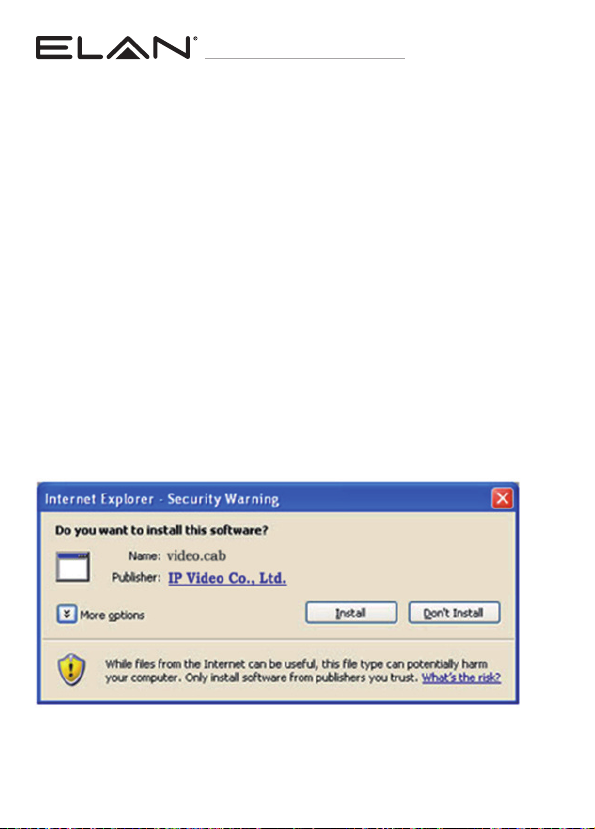
Once complete, you can access the
IP camera’s live video by entering the
default IP address via your Internet
browser. When the security warning
dialog box appears, click OK to
download the ActiveX plug-in directly
from the IP camera.
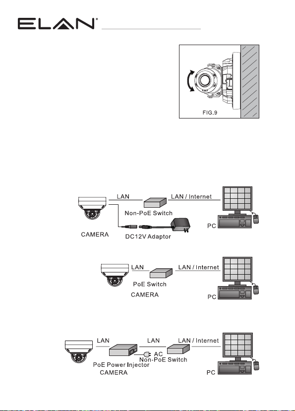
INTERNET BROWSER SETTINGS
& APPLICATION REQUIRED
Username
Password
ELAN
3526

10 www.elanhomesystems.com
QUICK START GUIDE
Universal ActiveX software components are required for online display of
MJPEG or H.264 Full HD video. When you log in to the IP camera from
Internet Explorer, a security warning dialog box will prompt the installation
of the Universal ActiveX plug-in. Click Install to download it.
BROWSER CONNECTION REQUIREMENTS
If using in ELAN automation system, please refer to the integration note at the
beginning, and use the ELAN configurator for Auto-Discover/Auto-Configure
features. If installing camera with no ELAN system, follow the browser
connections below.
Before accessing the IP camera, make sure that the camera’s RJ-45 network,
audio, and power cables are properly connected. To set the IP address,
consult your network administrator for an available IP address. The default IP
address for each IP camera is 192.168.0.200. Users can use the default IP
address to verify the camera’s network connection.
CONFIGURING IP CAMERAS

11
contact techsupport@elanhomesystems.com
EL-IP-ODF2-WH /EL-IP-ODF4-WH /E L- I P - O D V 2- W H
E L- I P - O D V4 - W H /EL-IP-ODV2-BK/EL-IP-ODA4-WH/EL-IP-ODA4-BK
To restore the hardware to factory default settings, please follow these steps:
1. Press and hold RESET for 10 seconds before releasing.
2. The camera will be restored to factory default settings after approximately
90 seconds and will reboot automatically.
3. Search for the IP device.
4. Start the IP device via an Internet browser.
5. Enter the default username “ELAN” and password “3526” to operate.
NOTE: Cameras are configured to use DHCP by default but will revert to the
default address 192.168.0.200 if a DHCP server is not available.
EMERGENCY FACTORY DEFAULT

main:
1 (800) 472-5555 – US
1 (707) 283-5900 – International
1 (707) 283-5901 – Fax
tech support:
web:
elanhomesystems.com
10024103 Rev-B, 10/2019
ELAN®is a registered trademark of Nortek Security & Control, LLC.
All rights reserved. ©2019 Nortek Security & Control.
This manual suits for next models
6
Table of contents
Other Elan Security Camera manuals