elbag Energietechnik TS-01 User manual

Users manual
Temperature Monitoring Unit
TS-01
elbag Energietechnik GmbH
Brückenstraße 28 · D - 56348 Weisel
Telefon +49 (0) 67 74 / 18 - 0 · Telefax +49 (0) 67 74 / 18 128

TS-01 Temperature Monitoring Unit
ELBAG Energietechnik
____________________________________________________________________________Contents
1 Technical data................................................................................1
2 Block diagram................................................................................2
3 Technical Description....................................................................3
3.1 General.........................................................................................3
3.2 "PWR" Measuring Circuit.............................................................3
3.3 "temp >" Measuring Circuit..........................................................4
3.4 "temp >>" Measuring Circuit........................................................4
4 Connections...................................................................................4
4.1 Inputs ...........................................................................................4
4.2 Outputs.........................................................................................4
4.3 Installation Instructions ...............................................................5

TS-01 Temperature Monitoring Unit
ELBAG Energietechnik
__________________________________________________________________________________________
1 Technical data
Power supply: 24V - 270V ±10% DC
40V - 270V ±10%, AC 50-60Hz
Power input: < 6VA or < 6W
PTC thermistor connection 2-wire connection
relay closing 3.0 kΩ< RON <3.2 kΩ
relay opening 1.4 kΩ< ROFF <1.6 kΩ
3-relays Max. voltage 230V
Max. current 6A
Max. switching capacity AC 1500 VA
DC 120 W
Re1: Power supply OK (green LED)
Re2: PTC thermistor connection temp. > triggered (yellow LED)
Re3: PTC thermistor connection temp. >> tripped (red LED)
Ambient temperature: -10 ... +50oC
Connection data: Rigid wire 0.2 – 2.5 mm2
Stranded wire 0.2 – 2.5 mm2
Dimensions: W x H x D 45mm x 99mm x 114.5 mm
Mounting: Snap-on mounting for symmetrical mounting rail
(35mm standard rail)
TS-01 Temperature Monitoring Unit
ELBAG Energietechnik
__________________________________________________________________________________________
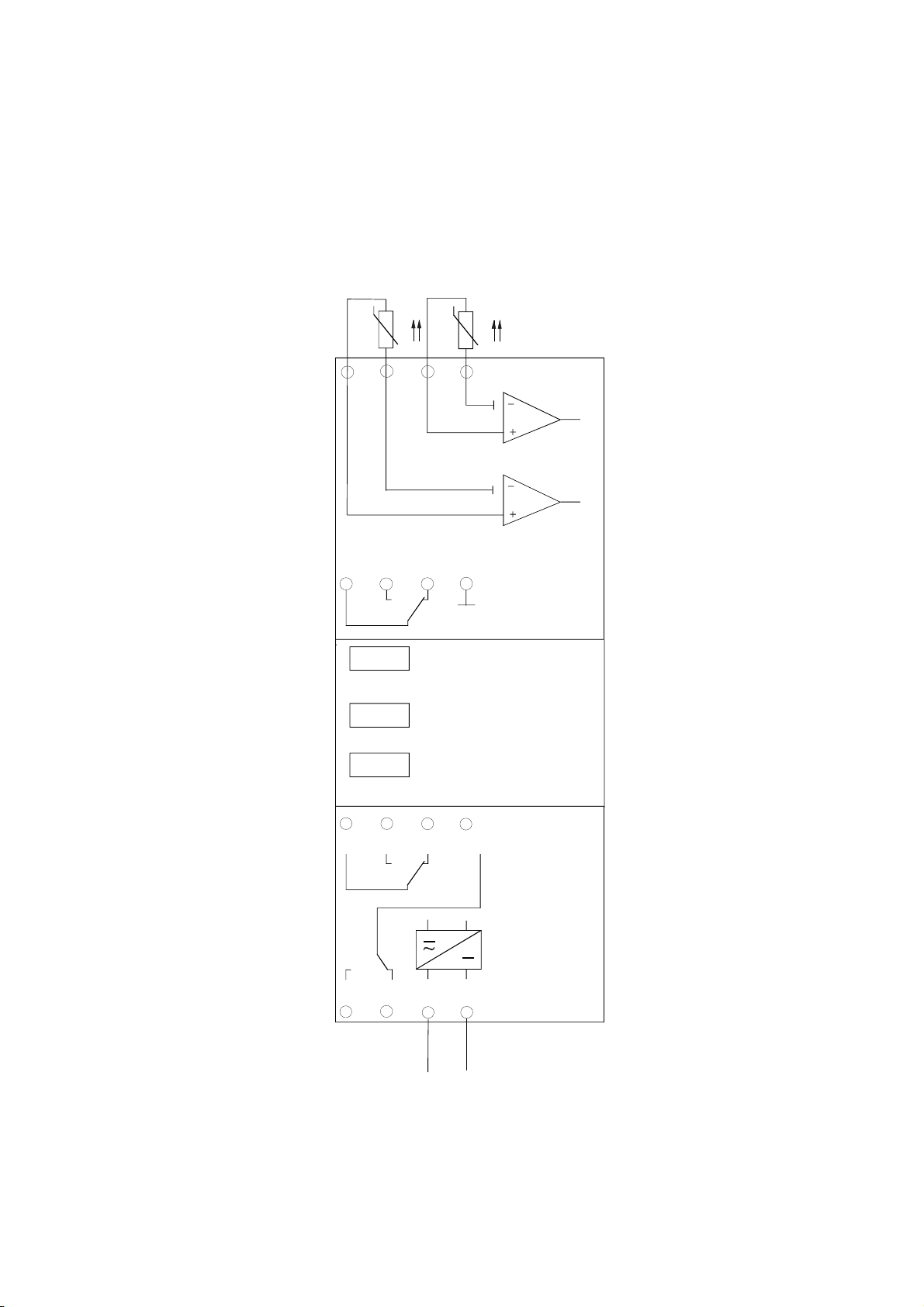
2 Block diagram
25 28 26 35
38 36 A1 A2
15 18 16
T2
Relay3
"on"
Power
24 - 270 +/-10% VDC
40 - 270 +/-10% VAC
PWR
T>
T>>
T>
ϑ
Relay2
"T>>"
Relay1
"T>"
T1 T3
ϑ
T>>
T4

TS-01 Temperature Monitoring Unit
ELBAG Energietechnik
__________________________________________________________________________________________
3 Technical description
3.1 General
The TS-01 temperaturecontrol unit is used to monitor the temperatureof equipment by
means of PTCs in accordance with DIN 44081/82 or DIN VDE 0660 Part 303.
Attached is an example of temperature monitoring of a transformer used for energy
distribution in the field of medium- and high-voltage systems.
Three relays, are assigned todifferent measuringcircuits. The significance of the
individual measuring circuits and the LEDs can be found in the following sections.
The PTC thermistors are to be designed in such a way that the threshold temperature of the
PTCs in the "temp. >" circuit is lower than that of the PTCs in the "temp. >>" circuit.
Example:
"temp. >" threshold temperature T1 = 120oC
"temp. >>" threshold temperature T2 = 150oC
Based onthe hysteresis behaviour of the PTC thermistors, the threshold " on " temperature
for the relays is slightly higher than the threshold " off " temperature.
As the operating point of the measuring circuits is in the kΩrange and the resistance of a
PTC thermistor is only a few hundred Ohm (when operated below the threshold
temperature), several PTC's can be connected in series (max. resistance < 1.4 kOhm).
3.2 "PWR" Measuring Circuit
Relay 3is used to monitor the supply voltage. Ifthe necessary operating voltageis applied
to the measuring circuit, the relay picks up and the green LED (PWR) lights. A changeover
contact is available as an output (terminals 35,38,36).
In case of power failure, Relay 3drops, as well as relaysRelay1and 2, independent of their
previous position. The relays are in the position as shown in chapter 4.1 and 4.2.
Bypower return, Relay 3, energizes, the position of Relays1and 2is depending of
the value of the connected PTCs.

TS-01 Temperature Monitoring Unit
ELBAG Energietechnik
__________________________________________________________________________________________
3.3 "temp. >" Measuring Circuit
Ifthe threshold temperature of the PTCthermistor(f.ex. T1 = 120oC) isexceeded, Relay1
picks up and the yellow LED (T >) lights. A changeover contact is available for output
(terminals 15, 18, 16). Ifthe temperature decreases below the threshold, the relay drops out
and the LED extinguishes.
3.4 "temp. >>" Measuring Circuit
Ifthe threshold temperature of the PTCthermistor(f.ex. T1 = 150oC) isexceeded, Relay2
picks up and the red LED (T>>) lights. A changeover contact is available for output
(terminals 25,28,26). Ifthe temperature decreases below the threshold, the relay drops out
and the LED extinguishes.
4 Connections
4.1 Inputs
Terminalmarking Connection
T1, T2 PTC temp.> *
T3, T4 PTC temp.>> *
A1, (L / +); A2, (N / -) 24 - 270V ±10% DC,
40 – 270V ±10% AC / 50 - 60Hz
* Standard value for PTC circuits: Rseries < 1.4 kΩàsee also
section 4.3 Installation instructions
4.2 Outputs
Terminal marking Connection
15,18,16 Changeover contact temp. > (Relay 1)
25,28,26 Changeover contact temp. >> (Relay 2)
35,38,36 Changeover contact PWR/ON (Relay 3)
x5= Common contact
x6 = NC contact
x8 = NO contact

TS-01 Temperature Monitoring Unit
ELBAG Energietechnik
__________________________________________________________________________________________
4.3 Installation instructions
PTC > and PTC >>
Connection variants Action
2-wire connection Remove premounted 1 kΩresistors,
connect PTC> to terminal T1/T2 and PTC>> to terminal
T3/T4 (both protected against polarity reversal)
No PTC> connection Leave mounted resistor connected to terminal T1/T2
No PTC>> connection Leave mounted resistor connected to terminal T3/T4
Connection to power supply
Do not connect the power cable until the sensor cables have been secured!
The system connection is protected against polarity reversal (for AC and DC supply).
The TS-01 is without PE connection and only has terminals for L/+ and N/–.
APE conductor however can be connected to the ⊥terminalfor the PTC probes .
The power supply unit is isolated from the measuring circuits.
Permitted resistance ranges for PTC circuits T> and T>>
The PTC circuit may consist of both a single PTC or a PTC connected in series. In this case,
to ensure flawless operation of the TS-01 temperature monitoring unit, the resistances values
in the following table below should be observed in all cases to guarantee proper operation of
the TS-01 temperature monitoring
In the case of series connection, the total resistance of the PTC
chain should be àR series< 1.4 kΩ.
Function Resistance range
Fault recognition, short circuit 0 Ω– 15 Ω
Measuring range of PTC 50 Ω– 50 kΩ
Fault recognition, open circuit 100 kΩ– ∞
The standard value of a PTC in accordance with DIN 44081/82 or DIN VDE 0660 Part 303
is ≤250Ωwithin the range of –20°C to TNF-20K and ≥4000Ωat TNF+15K. The resistance of
the PTC's has to within these limits ( TNF is the designated reaction temperature of a PTC).
Table of contents
Popular Measuring Instrument manuals by other brands

Powerfix Profi
Powerfix Profi 278296 Operation and safety notes

Test Equipment Depot
Test Equipment Depot GVT-427B user manual

Fieldpiece
Fieldpiece ACH Operator's manual

FLYSURFER
FLYSURFER VIRON3 user manual

GMW
GMW TG uni 1 operating manual

Downeaster
Downeaster Wind & Weather Medallion Series instruction manual

Hanna Instruments
Hanna Instruments HI96725C instruction manual

Nokeval
Nokeval KMR260 quick guide

HOKUYO AUTOMATIC
HOKUYO AUTOMATIC UBG-05LN instruction manual

Fluke
Fluke 96000 Series Operator's manual

Test Products International
Test Products International SP565 user manual

General Sleep
General Sleep Zmachine Insight+ DT-200 Service manual


